headlight bulb YAMAHA GRIZZLY 550 2013 Owners Manual
[x] Cancel search | Manufacturer: YAMAHA, Model Year: 2013, Model line: GRIZZLY 550, Model: YAMAHA GRIZZLY 550 2013Pages: 174, PDF Size: 4.21 MB
Page 11 of 174

Checking the wheel hub bearings ............ 8-55
Checking the stabilizer bushes ................ 8-55
Lubricating the rear knuckle pivots ........... 8-55
Lubricating the steering shaft ................... 8-56
Battery ...................................................... 8-56
Replacing a fuse ...................................... 8-59
Replacing a headlight bulb ....................... 8-61
Adjusting a headlight beam ...................... 8-63
Replacing the tail/brake light bulb ............ 8-63
Removing a wheel .................................... 8-64
Installing a wheel ...................................... 8-65
Troubleshooting ....................................... 8-66
Troubleshooting charts ............................. 8-67
CLEANING AND STORAGE .......................... 9-1 Cleaning ..................................................... 9-1
Storage ....................................................... 9-2
SPECIFICATIONS ...................................... 10-1
CONSUMER INFORMATION ...................... 11-1 Identification numbers .............................. 11-1
U1HS61E0.book Page 3 Wednesday, May 23, 2012 5:24 PM
Page 153 of 174

8-61
8
3. Turn the key to “ ” (on) and turn on the elec- trical circuits to check if the devices operate. 4. If the fuse immediately blows again, have a
Yamaha dealer check the electrical system.
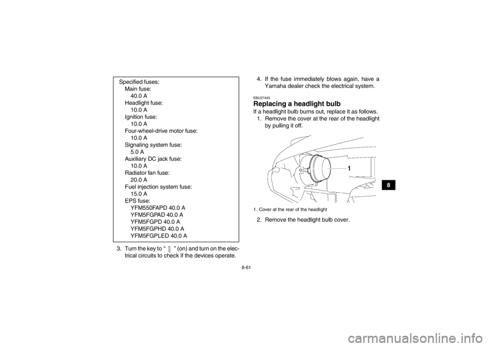
EBU27443Replacing a headlight bulb If a headlight bulb burns out, replace it as follows.1. Remove the cover at the rear of the headlight by pulling it off.
2. Remove the headlight bulb cover.
Specified fuses:
Main fuse:40.0 A
Headlight fuse: 10.0 A
Ignition fuse: 10.0 A
Four-wheel-drive motor fuse: 10.0 A
Signaling system fuse: 5.0 A
Auxiliary DC jack fuse: 10.0 A
Radiator fan fuse: 20.0 A
Fuel injection system fuse: 15.0 A
EPS fuse: YFM550FAPD 40.0 A
YFM5FGPAD 40.0 A
YFM5FGPD 40.0 A
YFM5FGPHD 40.0 A
YFM5FGPLED 40.0 A1. Cover at the rear of the headlight
U1HS61E0.book Page 61 Wednesday, May 23, 2012 5:24 PM
Page 154 of 174

8-62
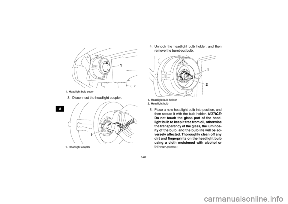
83. Disconnect the headlight coupler. 4. Unhook the headlight bulb holder, and then
remove the burnt-out bulb.
5. Place a new headlight bulb into position, and then secure it with the bulb holder. NOTICE:
Do not touch the glass part of the head-
light bulb to keep it free from oil, otherwise
the transparency of the glass, the luminos-
ity of the bulb, and the bulb life will be ad-
versely affected. Thoroughly clean off any
dirt and fingerprints on the headlight bulb
using a cloth moistened with alcohol or
thinner.
[ECB00651]
1. Headlight bulb cover
1. Headlight coupler
1. Headlight bulb holder
2. Headlight bulb
U1HS61E0.book Page 62 Wednesday, May 23, 2012 5:24 PM
Page 155 of 174
![YAMAHA GRIZZLY 550 2013 Owners Manual 8-63
8
6. Connect the headlight coupler.
7. Install the headlight bulb cover.
NOTICE:
Make sure the headlight bulb cover is se-
curely fitted and seated properly.
[ECB01080]
8. Install the cover at YAMAHA GRIZZLY 550 2013 Owners Manual 8-63
8
6. Connect the headlight coupler.
7. Install the headlight bulb cover.
NOTICE:
Make sure the headlight bulb cover is se-
curely fitted and seated properly.
[ECB01080]
8. Install the cover at](/img/51/50411/w960_50411-154.png)
8-63
8
6. Connect the headlight coupler.
7. Install the headlight bulb cover.
NOTICE:
Make sure the headlight bulb cover is se-
curely fitted and seated properly.
[ECB01080]
8. Install the cover at the rear of the headlight.
9. Adjust the headlight beam if necessary.EBU25551Adjusting a headlight beam NOTICEECB00690It is advisable to have a Yamaha dealer make
this adjustment.
To raise a headlight beam, turn the headlight beam
adjusting screw in direction (a).
To lower a headlight beam, turn the adjusting
screw in direction (b).EBU25642Replacing the tail/brake light bulb If the tail/brake light bulb burns out, replace it as
follows. 1. Remove panel H. (See page 8-10.)
2. Remove the tail/brake light bulb holder (to- gether with the bulb) by turning it counter-
clockwise.
1. Do not touch the glass part of the bulb.
1. Headlight beam adjusting screw
U1HS61E0.book Page 63 Wednesday, May 23, 2012 5:24 PM
Page 167 of 174

10-4
10
Tire air pressure (measured on cold tires):Recommended:Front:35.0 kPa (0.350 kgf/cm², 5.0 psi)
Rear: 30.0 kPa (0.300 kgf/cm², 4.4 psi)
Minimum:
Front:32.0 kPa (0.320 kgf/cm², 4.6 psi)
Rear:
27.0 kPa (0.270 kgf/cm², 4.0 psi)Front wheel:Wheel type:Panel wheel
Rim size:
12 x 6.0ATRear wheel:Wheel type:Panel wheel
Rim size:
12 x 7.5ATFront brake:Type:Disc brake
Operation:
Right hand operation
Specified brake fluid: DOT 4Rear brake:Type:
Disc brake Operation:
Left hand and right foot operation
Specified brake fluid: DOT 4
Front suspension:Type:Double wishbone
Spring/shock absorber type: Coil spring/oil damper
Wheel travel:
180 mm (7.1 in)Rear suspension:Type:Double wishbone
Spring/shock absorber type:
Coil spring/gas-oil damper
Wheel travel: 230 mm (9.1 in)Electrical system:Ignition system:
TCI
Charging system: AC magnetoBattery:Model:
YTX20L-BS
Voltage, capacity: 12 V, 18.0 AhHeadlight:Bulb type:
Halogen bulb
U1HS61E0.book Page 4 Wednesday, May 23, 2012 5:24 PM
Page 168 of 174

10-5
10
Bulb voltage, wattage × quantity:Headlight:
12 V, 35.0/35.0 W × 2
Tail/brake light:
12 V, 5.0/21.0 W × 1
Meter lighting: EL (Electroluminescent)
Neutral indicator light: LED
Reverse indicator light:
LED
Coolant temperature warning light: LED
Engine trouble warning light: LED
EPS warning light:
YFM550FAPD LED
YFM5FGPAD LED
YFM5FGPD LED
YFM5FGPHD LED
YFM5FGPLED LED
Park indicator light:
LED
On-Command four-wheel-drive/differential gear lock
indicator:
LCD
High-range indicator light: LED
Low-range indicator light: LED
Differential gear lock indicator light:
LED
Fuses:Main fuse:40.0 A
Fuel injection system fuse:
15.0 A
EPS fuse: YFM550FAPD 40.0 A
YFM5FGPAD 40.0 A
YFM5FGPD 40.0 A
YFM5FGPHD 40.0 A
YFM5FGPLED 40.0 A
Headlight fuse: 10.0 A
Signaling system fuse: 5.0 A
Ignition fuse:
10.0 A
Auxiliary DC jack fuse: 10.0 A
Four-wheel-drive motor fuse: 10.0 A
Radiator fan fuse:
20.0 AEBU30401For Europe only
The figures quoted are emission levels and are not
necessarily safe working levels. Whilst there is a
correlation between the emission and exposure
levels, this cannot be used reliably to determine
U1HS61E0.book Page 5 Wednesday, May 23, 2012 5:24 PM
Page 172 of 174

INDEX
AAccessories and loading ................................................ 6-6
Accessories, auxiliary jack ........................................... 4-23
Air filter element, cleaning ............................................ 8-39
Axle boots .................................................................... 8-52BBattery .......................................................................... 8-56
Brake fluid, changing .................................................... 8-49
Brake fluid level, checking ............................................ 8-48
Brake lever, front .......................................................... 4-14
Brake levers, checking and lubricating ......................... 8-53
Brake pads, checking the front and rear ...................... 8-47
Brake pedal and rear brake lever ................................. 4-14
Brake pedal, checking and lubricating ......................... 8-54
Brake pedal free play, adjusting ................................... 8-50
Brakes .......................................................................... 8-46
Brakes, front and rear .................................................... 5-3CCables, checking and lubricating ................................. 8-53
Carrier, front ................................................................. 4-21
Carrier, rear .................................................................. 4-21
Chassis fasteners ........................................................... 5-7
Cleaning ......................................................................... 9-1
Coolant .................................................................. 5-3, 8-32
Coolant temperature warning light ................................. 4-3DDifferential gear oil ................................................ 5-3, 8-29
Drive select lever .......................................................... 4-15 Drive select lever and driving in reverse ........................ 6-2
Drive select lever safety system cable, adjusting ......... 8-46
EEngine break-in .............................................................. 6-4
Engine oil ....................................................................... 5-3
Engine oil and oil filter cartridge ................................... 8-22
Engine stop switch ......................................................... 4-7
Engine trouble warning light ........................................... 4-3
EPS warning light (for EPS model) ................................ 4-3FFinal gear oil .......................................................... 5-3, 8-27
Four-wheel-drive/differential gear lock indicator ............ 4-4
Front and rear brake lever free play, checking ............. 8-49
Fuel ....................................................................... 4-16, 5-3
Fuel tank cap ................................................................ 4-15
Fuses, replacing ........................................................... 8-59HHandlebar switches ........................................................ 4-7
Headlight beam, adjusting ............................................ 8-63
Headlight bulb, replacing .............................................. 8-61
High-range indicator light ............................................... 4-2
Horn switch .................................................................... 4-8IIdentification numbers .................................................. 11-1
Indicator lights and warning lights .................................. 4-2
Instruments, lights and switches .................................... 5-7LLabel locations ............................................................... 1-1
U1HS61E0.book Page 1 Wednesday, May 23, 2012 5:24 PM