check engine YAMAHA GRIZZLY 700 2015 User Guide
[x] Cancel search | Manufacturer: YAMAHA, Model Year: 2015, Model line: GRIZZLY 700, Model: YAMAHA GRIZZLY 700 2015Pages: 172, PDF Size: 4.32 MB
Page 61 of 172
6-1
6
EBU19882
OPERATION
EBU19902Read the Owner’s Manual carefully before riding
the ATV. If there is a control or function you do not
understand, ask your Yamaha dealer.
WARNING
EWB00632Read the Owner’s Manual carefully to become
familiar with all controls in order to help pre-
vent any loss of control, which could cause an
accident or injury. EBU30501Starting the engineNOTICEECB00151See the “Engine break-in” section on page 6-4
prior to operating the engine for the first time. 1. Turn the key to “ ” (on) and the engine stopswitch to “ ”.
The following warning lights should come on
for a few seconds, then go off.
Coolant temperature warning light
Engine trouble warning light
The EPS warning light should come on, then
go off when the engine is started.
NOTICEECB00825If a warning light does not go off, see page 4-2
for the corresponding warning light circuit
check. To avoid possible damage, do not oper-
ate the ATV if a warning light stays on. 2. Apply the brake pedal, and then shift the drive select lever into the neutral or park position.
The corresponding indicator light should
come on. If the indicator light does not come
on, have a Yamaha dealer check the electrical
circuit.TIPThis model is equipped with an ignition circuit cut-
off system. The engine can be started under the
following conditions:
The drive select lever is in the neutral or park po-
sition.
UB3860E0.book Page 1 Monday, July 14, 2014 10:34 AM
Page 64 of 172
6-4
6
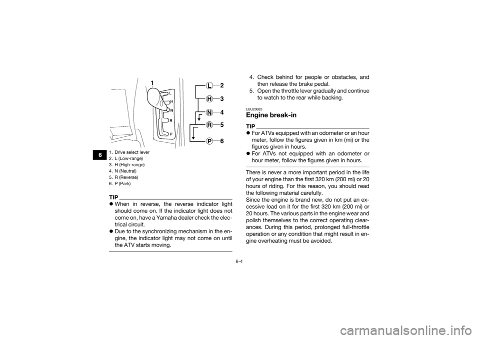
TIPWhen in reverse, the reverse indicator light
should come on. If the indicator light does not
come on, have a Yamaha dealer check the elec-
trical circuit.
Due to the synchronizing mechanism in the en-
gine, the indicator light may not come on until
the ATV starts moving.
4. Check behind for people or obstacles, and
then release the brake pedal.
5. Open the throttle lever gradually and continue to watch to the rear while backing.EBU20683Engine break-inTIPFor ATVs equipped with an odometer or an hour
meter, follow the figures given in km (mi) or the
figures given in hours.
For ATVs not equipped with an odometer or
hour meter, follow the figures given in hours. There is never a more important period in the life
of your engine than the first 320 km (200 mi) or 20
hours of riding. For this reason, you should read
the following material carefully.
Since the engine is brand new, do not put an ex-
cessive load on it for the first 320 km (200 mi) or
20 hours. The various parts in the engine wear and
polish themselves to the correct operating clear-
ances. During this period, prolonged full-throttle
operation or any condition that might result in en-
gine overheating must be avoided.
1. Drive select lever
2. L (Low-range)
3. H (High-range)
4. N (Neutral)
5. R (Reverse)
6. P (Park)
L 2H 3N4R5P6
UB3860E0.book Page 4 Monday, July 14, 2014 10:34 AM
Page 65 of 172
6-5
6
0–160 km (0–100 mi) or 0–10 hours
Avoid prolonged operation above 1/2 throttle.
Vary the speed of the ATV regularly. Do not oper-
ate it at one set throttle position.
160–320 km (100–200 mi) or 10–20 hours
Avoid prolonged operation above 3/4 throttle. Rev
the engine freely, but do not use full throttle at any
time.
320 km (200 mi) or 20 hours and beyond
The ATV can now be operated normally.
NOTICEECB00221If any engine trouble should occur during the
engine break-in period, immediately have a
Yamaha dealer check the ATV. EBU27322ParkingWhen parking the ATV, stop the engine, and shift
the drive select lever into the park position.
EBU29901Parking on a slope
WARNING
EWB00861Avoid parking on hills or other inclines. Parking
on a hill or other incline could cause the ATV to
roll out of control, increasing the chance of an
accident. If you must park on an incline, place
the ATV transversely across the incline, stop
the engine, shift the drive select lever to the
park position, and then block the front and rear
wheels with rocks or other objects.
Do not park the ATV at all on hills that are so
steep you could not walk up them easily. 1. Bring the ATV to a stop by applying the brakes.
2. Stop the engine.
3. With the brake pedal applied, shift the drive select lever to the park position.
UB3860E0.book Page 5 Monday, July 14, 2014 10:34 AM
Page 76 of 172
![YAMAHA GRIZZLY 700 2015 User Guide 7-8
7an overturn. Never attempt stunts, such as
wheelies or jumps. Don’t try to show off.
[EWB01482]Modifications and accessories
Never modify this ATV through improper installa-
tion or use of acce YAMAHA GRIZZLY 700 2015 User Guide 7-8
7an overturn. Never attempt stunts, such as
wheelies or jumps. Don’t try to show off.
[EWB01482]Modifications and accessories
Never modify this ATV through improper installa-
tion or use of acce](/img/51/50458/w960_50458-75.png)
7-8
7an overturn. Never attempt stunts, such as
wheelies or jumps. Don’t try to show off.
[EWB01482]Modifications and accessories
Never modify this ATV through improper installa-
tion or use of accessories or other modification. All
parts and accessories added to this ATV should
be genuine Yamaha or equivalent components
designed for use on this ATV and should be in-
stalled and used according to instructions. If you
have questions, consult an authorized ATV dealer.
WARNING! Operating this ATV with improper modifications may cause changes in handling
which in some situations could lead to an acci-
dent.
[EWB01492]
Exhaust system
WARNING
EWB01502 Dry grass or brush or other combustible ma-
terial accumulated around the engine area
could catch fire. Do not operate, idle, or park
the ATV in dry grass or other dry ground cov-
er. Keep the engine area free of dry grass,
brush, or other combustible material.
Someone touching the exhaust system dur-
ing or after operation could be burned. Do
not touch the hot exhaust system. Do not
park the ATV in a place where others might
be likely to touch it. The muffler and other engine parts become ex-
tremely hot during operation and remain hot after
the engine has stopped. To reduce the risk of fire
during operation or after leaving the ATV, do not
let brush, grass and other materials collect under
the vehicle, near the muffler or exhaust pipe, or
next to other hot parts. Check under the vehicle
after operating in areas where combustible mate-
rials may have collected. Do not idle or park the
vehicle in long dry grass or other dry ground cov-
er.
UB3860E0.book Page 8 Monday, July 14, 2014 10:34 AM
Page 84 of 172
7-16
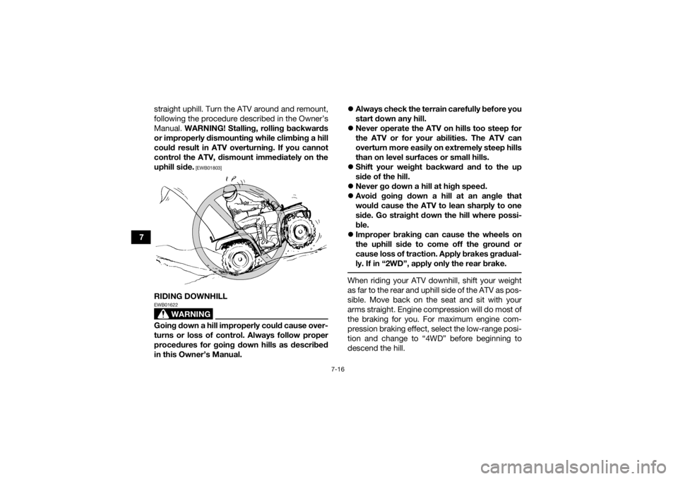
7straight uphill. Turn the ATV around and remount,
following the procedure described in the Owner’s
Manual.
WARNING! Stalling, rolling backwards
or improperly dismounting while climbing a hill
could result in ATV overturning. If you cannot
control the ATV, dismount immediately on the
uphill side.
[EWB01803]
RIDING DOWNHILL
WARNING
EWB01622Going down a hill improperly could cause over-
turns or loss of control. Always follow proper
procedures for going down hills as described
in this Owner’s Manual.
Always check the terrain carefully before you
start down any hill.
Never operate the ATV on hills too steep for
the ATV or for your abilities. The ATV can
overturn more easily on extremely steep hills
than on level surfaces or small hills.
Shift your weight backward and to the up
side of the hill.
Never go down a hill at high speed.
Avoid going down a hill at an angle that
would cause the ATV to lean sharply to one
side. Go straight down the hill where possi-
ble.
Improper braking can cause the wheels on
the uphill side to come off the ground or
cause loss of traction. Apply brakes gradual-
ly. If in “2WD”, apply only the rear brake.
When riding your ATV downhill, shift your weight
as far to the rear and uphill side of the ATV as pos-
sible. Move back on the seat and sit with your
arms straight. Engine compression will do most of
the braking for you. For maximum engine com-
pression braking effect, select the low-range posi-
tion and change to “4WD” before beginning to
descend the hill.
UB3860E0.book Page 16 Monday, July 14, 2014 10:34 AM
Page 98 of 172

8-7
8
11*Shock absorber as-
semblies • Check operation and correct if necessary.
• Check for oil leakage and replace if necessary.
√√√
12 *Stabilizer bushes • Check for cracks or other damage, and replace if
necessary. √√√
13 *Rear knuckle pivots • Lubricate with lithium-soap-based grease. √√√
14 *Steering shaft • Lubricate with lithium-soap-based grease. √√√
15 *Steering system • Check operation and repair or replace if dam-
aged.
• Check toe-in and adjust if necessary. √√√√√
16 *Engine mount • Check for cracks or other damage, and replace if
necessary. √√√
17 *Axle boots • Check for cracks or other damage, and replace if
necessary. √√√√√
18 Engine oil • Change.
• Check ATV for oil leakage, and correct if neces-
sary. √ √√√
19 Engine oil filter car-
tridge • Replace.
√√√
20 Differential gear oil • Change.
• Check ATV for oil leakage, and correct if neces-
sary. √√
NO.
ITEM CHECK OR MAINTENANCE
JOB INITIAL
EVERY
Whichev-
er comes first month136612
km (mi) 320
(200) 1300
(800) 2500
(1600) 2500
(1600) 5000
(3200)
hours 20 80 160 160 320UB3860E0.book Page 7 Monday, July 14, 2014 10:34 AM
Page 111 of 172
8-20
8
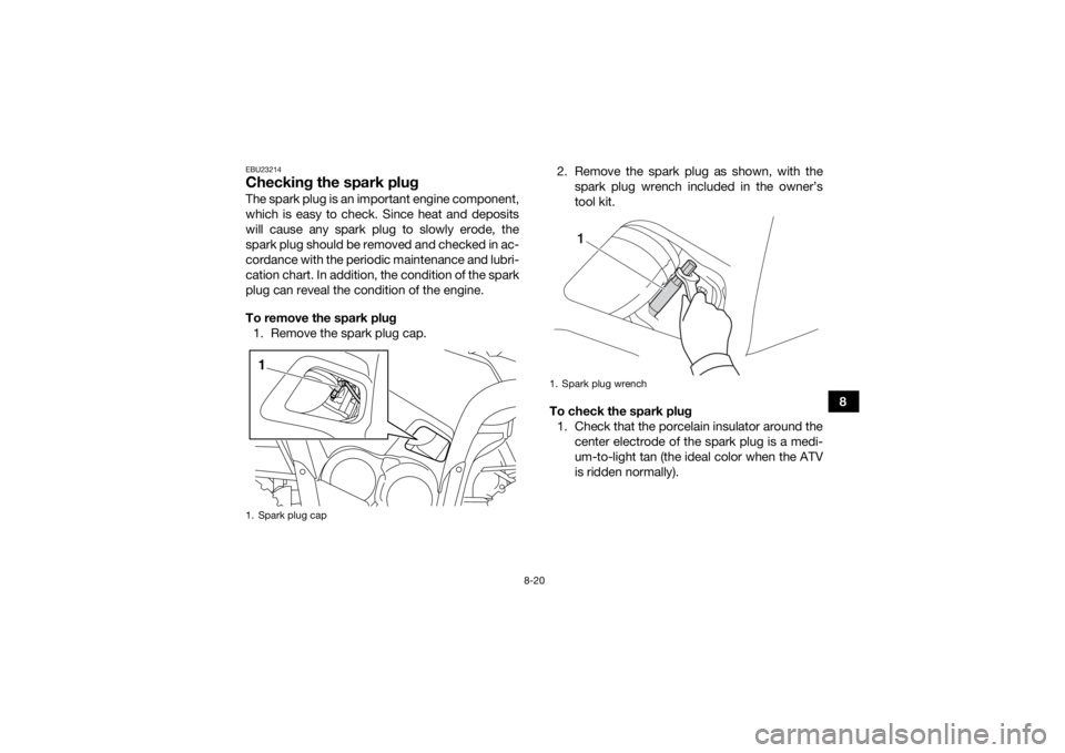
EBU23214Checking the spark plugThe spark plug is an important engine component,
which is easy to check. Since heat and deposits
will cause any spark plug to slowly erode, the
spark plug should be removed and checked in ac-
cordance with the periodic maintenance and lubri-
cation chart. In addition, the condition of the spark
plug can reveal the condition of the engine.
To remove the spark plug1. Remove the spark plug cap. 2. Remove the spark plug as shown, with the
spark plug wrench included in the owner’s
tool kit.
To check the spark plug 1. Check that the porcelain insulator around the center electrode of the spark plug is a medi-
um-to-light tan (the ideal color when the ATV
is ridden normally).1. Spark plug cap1
1. Spark plug wrench
1
UB3860E0.book Page 20 Monday, July 14, 2014 10:34 AM
Page 112 of 172
8-21
8
TIPIf the spark plug shows a distinctly different color,
the engine could be operating improperly. Do not
attempt to diagnose such problems yourself. In-
stead, have a Yamaha dealer check the ATV. 2. Check the spark plug for electrode erosionand excessive carbon or other deposits, and
replace it if necessary.
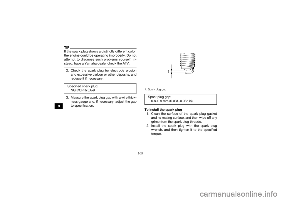
3. Measure the spark plug gap with a wire thick- ness gauge and, if necessary, adjust the gap
to specification.
To install the spark plug1. Clean the surface of the spark plug gasket and its mating surface, and then wipe off any
grime from the spark plug threads.
2. Install the spark plug with the spark plug wrench, and then tighten it to the specified
torque.
Specified spark plug:
NGK/CPR7EA-9
1. Spark plug gapSpark plug gap:0.8–0.9 mm (0.031–0.035 in)
UB3860E0.book Page 21 Monday, July 14, 2014 10:34 AM
Page 113 of 172
8-22
8
TIPIf a torque wrench is not available when installing
the spark plug, a good estimate of the correct
torque is 1/4–1/2 turn past finger tight. However,
the spark plug should be tightened to the speci-
fied torque as soon as possible. 3. Install the spark plug cap.EBU27468Engine oil and oil filter cartridgeThe engine oil level should be checked before
each ride. In addition, the oil must be changed and
the oil filter cartridge replaced at the intervals
specified in the periodic maintenance and lubrica-
tion chart.
To check the engine oil level1. Place the ATV on a level surface.
2. Check the engine oil level on a cold engine.
TIPIf the engine was started before checking the oil
level, be sure to warm up the engine sufficiently,
and then wait at least 10 minutes until the oil set-
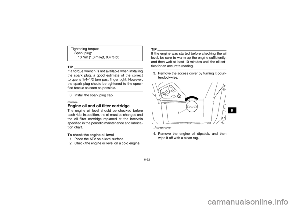
tles for an accurate reading. 3. Remove the access cover by turning it coun- terclockwise.
4. Remove the engine oil dipstick, and then wipe it off with a clean rag.
Tightening torque:
Spark plug:13 Nm (1.3 m·kgf, 9.4 ft·lbf)1. Access cover
UB3860E0.book Page 22 Monday, July 14, 2014 10:34 AM
Page 114 of 172
8-23
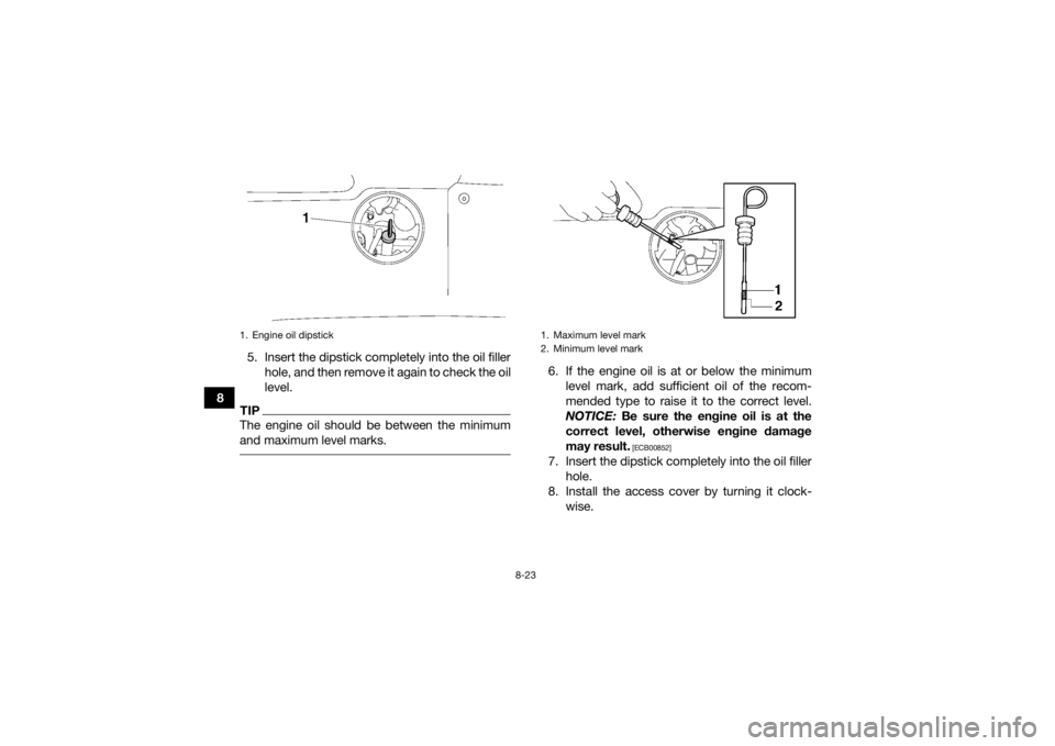
85. Insert the dipstick completely into the oil filler
hole, and then remove it again to check the oil
level.
TIPThe engine oil should be between the minimum
and maximum level marks.
6. If the engine oil is at or below the minimumlevel mark, add sufficient oil of the recom-
mended type to raise it to the correct level.
NOTICE: Be sure the engine oil is at the
correct level, otherwise engine damage
may result.
[ECB00852]
7. Insert the dipstick completely into the oil filler hole.
8. Install the access cover by turning it clock- wise.
1. Engine oil dipstick
1. Maximum level mark
2. Minimum level mark
UB3860E0.book Page 23 Monday, July 14, 2014 10:34 AM