YAMAHA GRIZZLY 700 2018 Owners Manual
GRIZZLY 700 2018
YAMAHA
YAMAHA
https://www.carmanualsonline.info/img/51/50449/w960_50449-0.png
YAMAHA GRIZZLY 700 2018 Owners Manual
Trending: dimensions, fuel type, fuel pressure, service indicator, fuel cap, auxiliary battery, fuse
Page 101 of 176
8-5
8
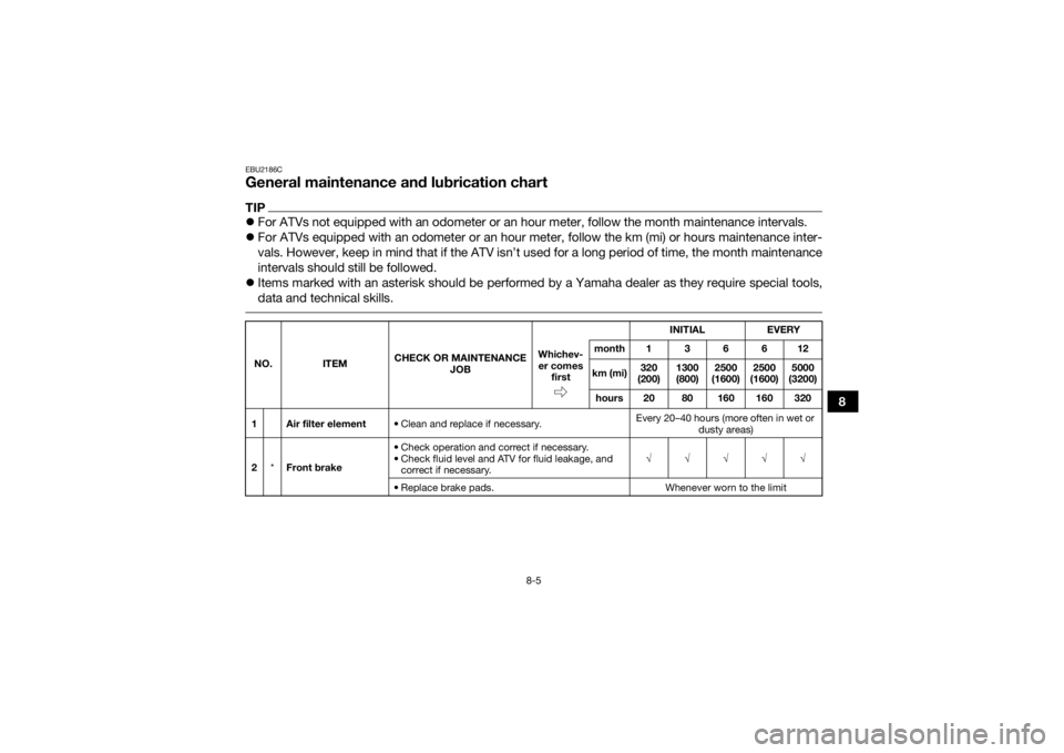
EBU2186CGeneral maintenance and lubrication chartTIP’ü¼For ATVs not equipped with an odometer or an hour meter, follow the month maintenance intervals.
’ü¼ For ATVs equipped with an odometer or an hour meter, follow the km (mi) or hours maintenance inter-
vals. However, keep in mind that if the ATV isnŌĆÖt used for a long period of time, the month maintenance
intervals should still be followed.
’ü¼ Items marked with an asterisk should be performed by a Yamaha dealer as they require special tools,
data and technical skills. NO. ITEM CHECK OR MAINTENANCE
JOB INITIAL
EVERY
Whichev- er comes first month136612
km (mi) 320
(200) 1300
(800) 2500
(1600) 2500
(1600) 5000
(3200)
hours 20 80 160 160 320
1 Air filter element ŌĆó Clean and replace if necessary. Every 20ŌĆō40 hours (more often in wet or
dusty areas)
2 *Front brake ŌĆó Check operation and correct if necessary.
ŌĆó Check fluid level and ATV for fluid leakage, and
correct if necessary. ŌłÜŌłÜŌłÜŌłÜŌłÜ
ŌĆó Replace brake pads. Whenever worn to the limit
UB1A60E0.book Page 5 Wednesday, March 1, 2017 2:36 PM
Page 102 of 176

8-6
8
3*Rear brake ŌĆó Check operation and correct if necessary.
ŌĆó Check brake pedal free play and adjust if neces-
sary.
ŌĆó Check fluid level and ATV for fluid leakage, and correct if necessary. ŌłÜŌłÜŌłÜŌłÜŌłÜ
ŌĆó Replace brake pads. Whenever worn to the limit
4 *Brake hoses ŌĆó Check for cracks or other damage, and replace if
necessary. ŌłÜŌłÜŌłÜŌłÜ
ŌĆó Replace. Every 4 years
5 *Brake fluid ŌĆó Change. Every 2 years
6 *Wheels ŌĆó Check runout and for damage, and replace if nec-
essary. ŌłÜ ŌłÜŌłÜŌłÜ
7 *Tires ŌĆó Check tread depth and for damage, and replace if
necessary.
ŌĆó Check air pressure and balance, and correct if necessary. ŌłÜ ŌłÜŌłÜŌłÜ
8 *Wheel hub bearings ŌĆó Check for looseness or damage, and replace if
necessary. ŌłÜ ŌłÜŌłÜŌłÜ
9 *V- b e l t ŌĆó Check for wear, cracks or other damage, and re-
place if necessary. ŌłÜ ŌłÜŌłÜŌłÜ
10 *Chassis fasteners ŌĆó Make sure that all nuts, bolts, and screws are
properly tightened. ŌłÜŌłÜŌłÜŌłÜŌłÜ
NO. ITEM
CHECK OR MAINTENANCE
JOB INITIAL EVERY
Whichev-
er comes first month136612
km (mi) 320
(200) 1300
(800) 2500
(1600) 2500
(1600) 5000
(3200)
hours 20 80 160 160 320UB1A60E0.book Page 6 Wednesday, March 1, 2017 2:36 PM
Page 103 of 176

8-7
8
11*Shock absorber as-
semblies ŌĆó Check operation and correct if necessary.
ŌĆó Check for oil leakage and replace if necessary.
ŌłÜŌłÜŌłÜ
12 *Stabilizer bushes ŌĆó Check for cracks or other damage, and replace if
necessary. ŌłÜŌłÜŌłÜ
13 *Rear knuckle pivots ŌĆó Lubricate with lithium-soap-based grease. ŌłÜŌłÜŌłÜ
14 *Steering shaft ŌĆó Lubricate with lithium-soap-based grease. ŌłÜŌłÜŌłÜ
15 *Steering system ŌĆó Check operation and repair or replace if dam-
aged.
ŌĆó Check toe-in and adjust if necessary. ŌłÜŌłÜŌłÜŌłÜŌłÜ
16 *Engine mount ŌĆó Check for cracks or other damage, and replace if
necessary. ŌłÜŌłÜŌłÜ
17 *Axle boots ŌĆó Check for cracks or other damage, and replace if
necessary. ŌłÜŌłÜŌłÜŌłÜŌłÜ
18 Engine oil ŌĆó Change.
ŌĆó Check ATV for oil leakage, and correct if neces-
sary. ŌłÜ ŌłÜŌłÜŌłÜ
19 Engine oil filter car-
tridge ŌĆó Replace.
ŌłÜŌłÜŌłÜ
20 Differential gear oil ŌĆó Change.
ŌĆó Check ATV for oil leakage, and correct if neces-
sary. ŌłÜŌłÜ
NO. ITEM
CHECK OR MAINTENANCE
JOB INITIAL EVERY
Whichev- er comes first month136612
km (mi) 320
(200) 1300
(800) 2500
(1600) 2500
(1600) 5000
(3200)
hours 20 80 160 160 320UB1A60E0.book Page 7 Wednesday, March 1, 2017 2:36 PM
Page 104 of 176
8-8
8
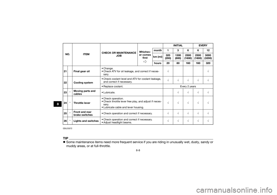
EBU23072TIP’ü¼Some maintenance items need more frequent service if you are riding in unusually wet, dusty, sandy or
muddy areas, or at full-throttle.21 Final gear oil ŌĆó Change.
ŌĆó Check ATV for oil leakage, and correct if neces-
sary. ŌłÜŌłÜ
22 Cooling system ŌĆó Check coolant level and ATV for coolant leakage,
and correct if necessary. ŌłÜŌłÜŌłÜŌłÜŌłÜ
ŌĆó Replace coolant. Every 2 years
23 *Moving parts and
cables ŌĆó Lubricate.
ŌłÜŌłÜŌłÜŌłÜ
24 *Throttle lever ŌĆó Check operation.
ŌĆó Check throttle lever free play, and adjust if neces-
sary.
ŌĆó Lubricate cable and lever housing. ŌłÜŌłÜŌłÜŌłÜŌłÜ
25 *Front and rear
brake switches ŌĆó Check operation and correct if necessary.
ŌłÜŌłÜŌłÜŌłÜŌłÜ
26 *Lights and switches ŌĆó Check operation and correct if necessary.
ŌĆó Adjust headlight beams. ŌłÜŌłÜŌłÜŌłÜŌłÜ
NO. ITEM
CHECK OR MAINTENANCE
JOB INITIAL EVERY
Whichev-
er comes first month136612
km (mi) 320
(200) 1300
(800) 2500
(1600) 2500
(1600) 5000
(3200)
hours 20 80 160 160 320UB1A60E0.book Page 8 Wednesday, March 1, 2017 2:36 PM
Page 105 of 176
8-9
8
’ü¼
Hydraulic brake service
ŌĆó Regularly check and, if necessary, correct the brake fluid level.
ŌĆó Every two years replace the internal components of the brake master cylinders and calipers, and
change the brake fluid.
ŌĆó Replace the brake hoses every four years and if cracked or damaged.
UB1A60E0.book Page 9 Wednesday, March 1, 2017 2:36 PM
Page 106 of 176
8-10
8
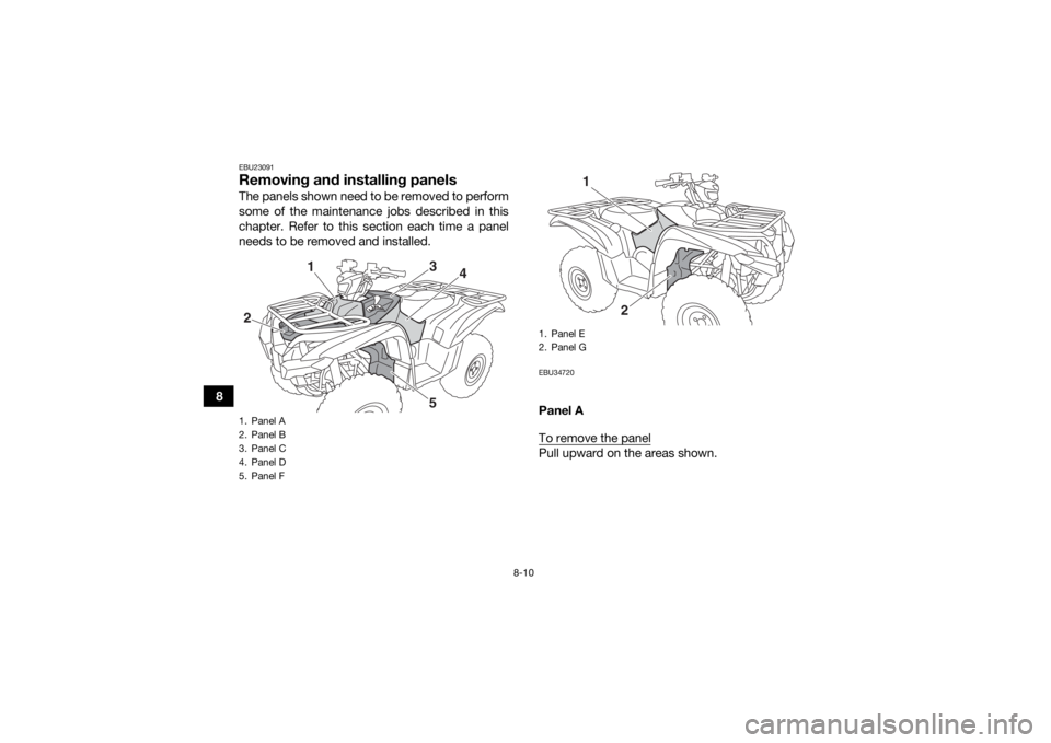
EBU23091Removing and installing panelsThe panels shown need to be removed to perform
some of the maintenance jobs described in this
chapter. Refer to this section each time a panel
needs to be removed and installed.
EBU34720Panel A
To remove the panelPull upward on the areas shown.
1. Panel A
2. Panel B
3. Panel C
4. Panel D
5. Panel F2
1
3
4
5
1. Panel E
2. Panel G
2
1
UB1A60E0.book Page 10 Wednesday, March 1, 2017 2:36 PM
Page 107 of 176
8-11
8
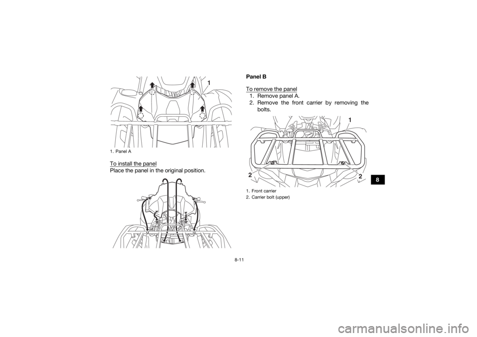
To install the panel
Place the panel in the original position. Panel B
To remove the panel
1. Remove panel A.
2. Remove the front carrier by removing the
bolts.
1. Panel A
1
1. Front carrier
2. Carrier bolt (upper)
1
2
2
UB1A60E0.book Page 11 Wednesday, March 1, 2017 2:36 PM
Page 108 of 176
8-12
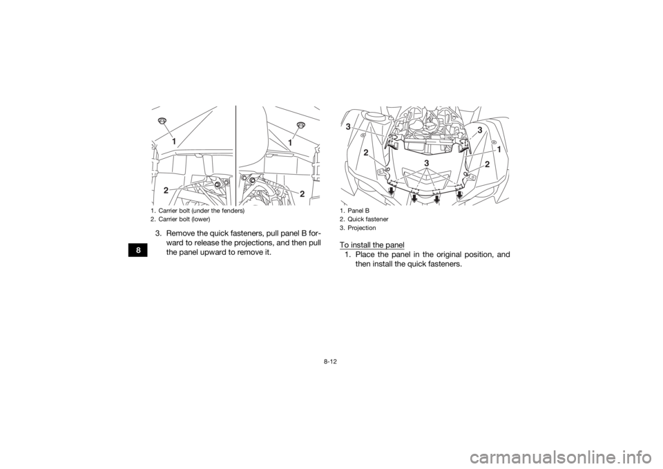
83. Remove the quick fasteners, pull panel B for-
ward to release the projections, and then pull
the panel upward to remove it. To install the panel
1. Place the panel in the original position, and
then install the quick fasteners.
1. Carrier bolt (under the fenders)
2. Carrier bolt (lower)
1
2
2
1
1. Panel B
2. Quick fastener
3. Projection3
3
1
2
3
2
UB1A60E0.book Page 12 Wednesday, March 1, 2017 2:36 PM
Page 109 of 176
8-13
8
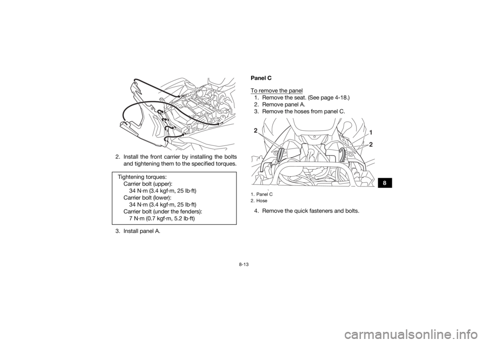
2. Install the front carrier by installing the bolts
and tightening them to the specified torques.
3. Install panel A. Panel C
To remove the panel
1. Remove the seat. (See page 4-18.)
2. Remove panel A.
3. Remove the hoses from panel C.
4. Remove the quick fasteners and bolts.
Tightening torques:
Carrier bolt (upper):34 N┬Ęm (3.4 kgf┬Ęm, 25 lb┬Ęft)
Carrier bolt (lower): 34 N┬Ęm (3.4 kgf┬Ęm, 25 lb┬Ęft)
Carrier bolt (under the fenders): 7 N┬Ęm (0.7 kgf┬Ęm, 5.2 lb┬Ęft)1. Panel C
2. Hose
21
2
UB1A60E0.book Page 13 Wednesday, March 1, 2017 2:36 PM
Page 110 of 176
8-14
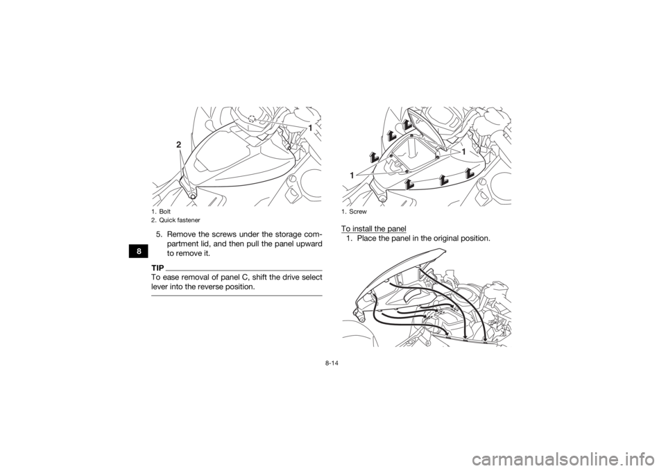
85. Remove the screws under the storage com-
partment lid, and then pull the panel upward
to remove it.
TIPTo ease removal of panel C, shift the drive select
lever into the reverse position.
To install the panel1. Place the panel in the original position.
1. Bolt
2. Quick fastener
1
2
1. Screw
1
1
UB1A60E0.book Page 14 Wednesday, March 1, 2017 2:36 PM
Trending: maintenance, lock, suspension, Idle Air Control, key, oil capacity, set clock


