Engine YAMAHA GRIZZLY 700 2022 User Guide
[x] Cancel search | Manufacturer: YAMAHA, Model Year: 2022, Model line: GRIZZLY 700, Model: YAMAHA GRIZZLY 700 2022Pages: 176, PDF Size: 4.75 MB
Page 36 of 176
5-7
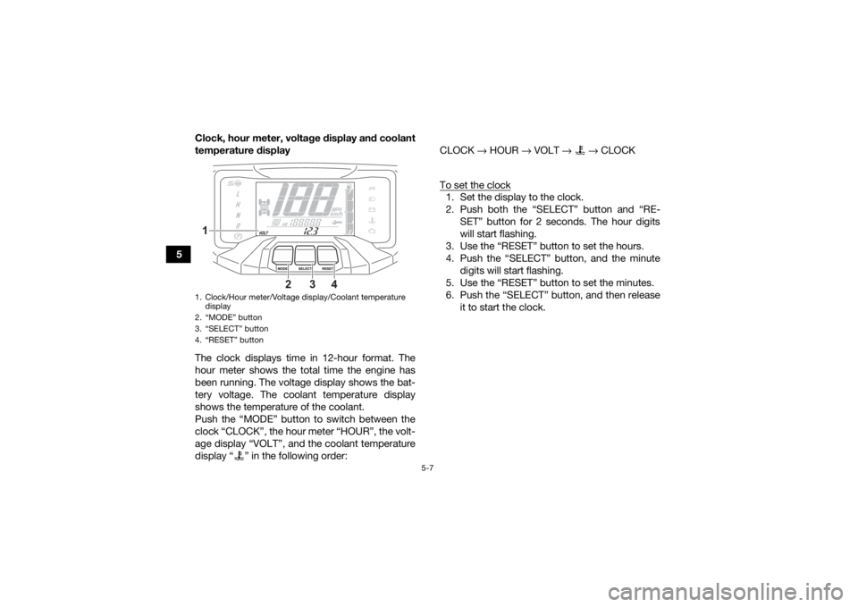
5Clock, hour meter, voltage display and coolant
temperature display
The clock displays time in 12-hour format. The
hour meter shows the total time the engine has
been running. The voltage display shows the bat-
tery voltage. The coolant temperature display
shows the temperature of the coolant.
Push the “MODE” button to switch between the
clock “CLOCK”, the hour meter “HOUR”, the volt-
age display “VOLT”, and the coolant temperature
display “ ” in the following order: CLOCK
→ HOUR → VOLT → → CLOCK
To set the clock
1. Set the display to the clock.
2. Push both the “SELECT” button and “RE- SET” button for 2 seconds. The hour digits
will start flashing.
3. Use the “RESET” button to set the hours.
4. Push the “SELECT” button, and the minute digits will start flashing.
5. Use the “RESET” button to set the minutes.
6. Push the “SELECT” button, and then release it to start the clock.
1. Clock/Hour meter/Voltage display/Coolant temperature display
2. “MODE” button
3. “SELECT” button
4. “RESET” button1
2
3
4
UBLT60E0.book Page 7 Tuesday, July 13, 2021 9:16 AM
Page 39 of 176
5-10
5
2. Use the “RESET” button to set the brightness
level.
3. Push the “SELECT” button to confirm the se- lected brightness level and exit the brightness
control mode.
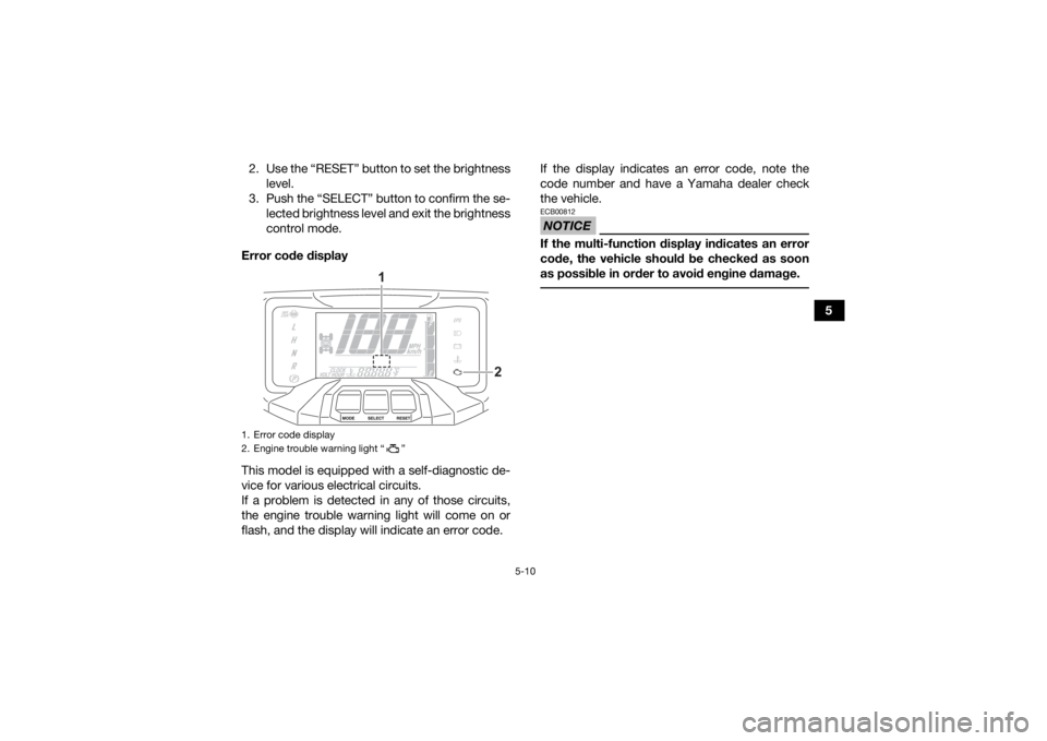
Error code display
This model is equipped with a self-diagnostic de-
vice for various electrical circuits.
If a problem is detected in any of those circuits,
the engine trouble warning light will come on or
flash, and the display will indicate an error code. If the display indicates an error code, note the
code number and have a Yamaha dealer check
the vehicle.
NOTICEECB00812If the multi-function display indicates an error
code, the vehicle should be checked as soon
as possible in order to avoid engine damage.
1. Error code display
2. Engine trouble warning light “ ”
2
1
UBLT60E0.book Page 10 Tuesday, July 13, 2021 9:16 AM
Page 40 of 176
5-11
5
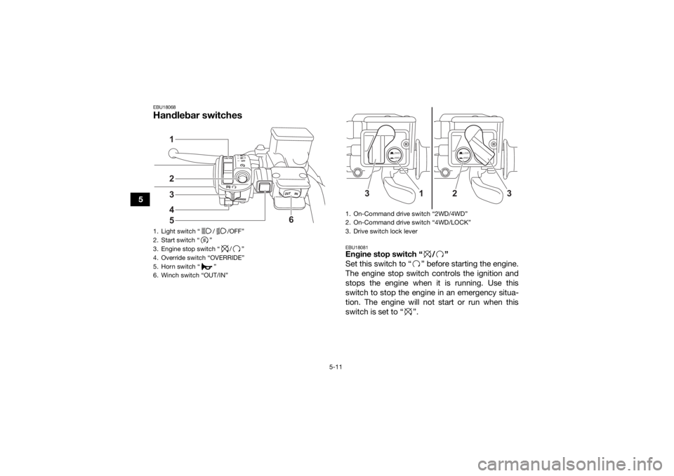
EBU18068Handlebar switches
EBU18081Engine stop switch “ / ”
Set this switch to “ ” before starting the engine.
The engine stop switch controls the ignition and
stops the engine when it is running. Use this
switch to stop the engine in an emergency situa-
tion. The engine will not start or run when this
switch is set to “ ”.
1. Light switch “ / /OFF”
2. Start switch “ ”
3. Engine stop switch “ / ”
4. Override switch “OVERRIDE”
5. Horn switch “ ”
6. Winch switch “OUT/IN”
432
6
15
1. On-Command drive switch
Page 41 of 176
5-12
5
EBU18102Start switch “ ”
Push this switch to crank the engine with the start-
er. See the starting instructions on page 7-1 prior
to starting the engine.EBU34123Light switch “ / /OFF”
Set this switch to “ ” to turn on the left and right
headlights (low beams) and the taillight. Set the
switch to “ ” to turn on the left and right head-
lights (high beams), the handlebar-mounted light ,
and the taillight. Set the switch to “OFF” to turn off
all the lights.NOTICEECB00046Do not use the headlights with the engine
turned off for an extended period of time. The
battery may discharge to the point that the
starter will not have enough power to crank the
engine. If this should happen, remove the bat-
tery and recharge it. (See page 9-52.) EBU18171Horn switch “ ”
Press the switch to sound the horn.
EBU39181Winch switch “OUT/IN”
This switch is used when operating the winch
(page 5-28). Read this manual and the Winch
Owner’s Manual completely before operating the
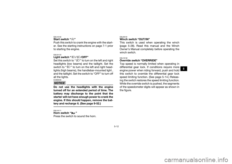
winch switch.EBU18192Override switch “OVERRIDE”
Top speed is normally limited when operating in
differential gear lock. If conditions require more
engine power when riding forward, push and hold
this switch to override the differential gear lock
speed limiting function. (See page 5-14.) Releas-
ing the switch restores the speed limiting function.
While the override switch is pushed, the segments
of the speedometer digits will appear as shown in
the figure.
UBLT60E0.book Page 12 Tuesday, July 13, 2021 9:16 AM
Page 44 of 176
5-15
5
TIPWhen the switch is set to “LOCK” or “4WD”, the
differential gear lock icon and indicator light will
flash until the differential gear is completely
locked or unlocked.
When the icon and indicator light are flashing,
turning the handlebar back and forth will help
the differential gear lock to engage or disen-
gage.
Riding before the differential gear is properly en-
gaged or disengaged (e.g., when the icon and
indicator light are flashing) will cause the vehicle
speed to be limited until the differential gear is
completely engaged or disengaged.
When the ATV is in four-wheel-drive differential
gear lock, the maximum traveling speed is limit-
ed to 35 km/h (22 mi/h). However, if conditions
require full engine power to be available, push
and hold the override switch to disable the dif-
ferential gear lock speed limiter. (See page
5-12.)
WARNING
EWB00141Always ride at a slow speed when the ATV is in
differential gear lock, and allow extra time and
distance for maneuvers.
All wheels turn at the same speed when the dif-
ferential gear is locked, so it takes more effort
to turn the ATV. The effort needed to turn in-
creases with the riding speed. You may lose
control and have an accident if you cannot
make a sharp enough turn for the speed you
are traveling.
UBLT60E0.book Page 15 Tuesday, July 13, 2021 9:16 AM
Page 45 of 176
5-16
5
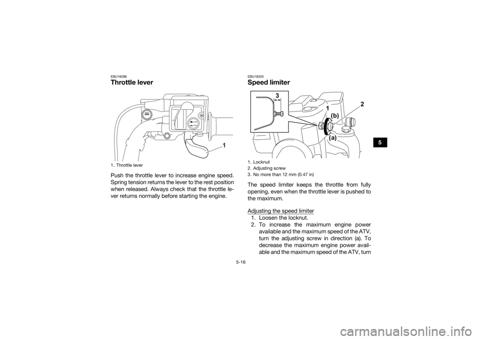
EBU18286Throttle leverPush the throttle lever to increase engine speed.
Spring tension returns the lever to the rest position
when released. Always check that the throttle le-
ver returns normally before starting the engine.
EBU18325Speed limiterThe speed limiter keeps the throttle from fully
opening, even when the throttle lever is pushed to
the maximum.
Adjusting the speed limiter1. Loosen the locknut.
2. To increase the maximum engine poweravailable and the maximum speed of the ATV,
turn the adjusting screw in direction (a). To
decrease the maximum engine power avail-
able and the maximum speed of the ATV, turn
1. Throttle lever
2WD
4WD
1
1. Locknut
2. Adjusting screw
3. No more than 12 mm (0.47 in)
2
1
3
(b)
(a)
UBLT60E0.book Page 16 Tuesday, July 13, 2021 9:16 AM
Page 48 of 176
5-19
5
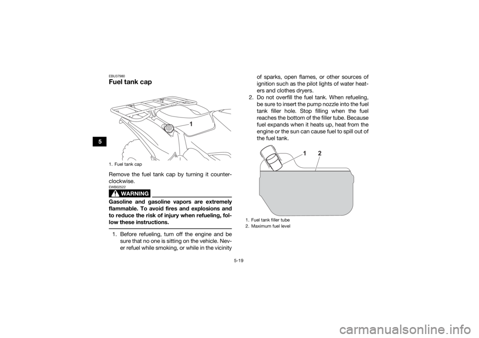
EBU37980Fuel tank capRemove the fuel tank cap by turning it counter-
clockwise.
WARNING
EWB02522Gasoline and gasoline vapors are extremely
flammable. To avoid fires and explosions and
to reduce the risk of injury when refueling, fol-
low these instructions. 1. Before refueling, turn off the engine and besure that no one is sitting on the vehicle. Nev-
er refuel while smoking, or while in the vicinity of sparks, open flames, or other sources of
ignition such as the pilot lights of water heat-
ers and clothes dryers.
2. Do not overfill the fuel tank. When refueling, be sure to insert the pump nozzle into the fuel
tank filler hole. Stop filling when the fuel
reaches the bottom of the filler tube. Because
fuel expands when it heats up, heat from the
engine or the sun can cause fuel to spill out of
the fuel tank.1. Fuel tank cap
1
1. Fuel tank filler tube
2. Maximum fuel level
2
1
UBLT60E0.book Page 19 Tuesday, July 13, 2021 9:16 AM
Page 50 of 176
5-21
5About the recommended fuel
This model’s engine has been designed to use
regular unleaded gasoline. The research octane
number should be 91 or higher. If knocking or
pinging occurs, try a gasoline of a different brand
or higher octane.
TIPGasoline containing ethanol can be used if the
ethanol content does not exceed 10% (E10). Gas-
oline containing methanol is not recommended
because it can cause damage to the fuel system
or vehicle performance problems. NOTICEECB00071Use only unleaded gasoline. The use of leaded
gasoline will cause severe damage to internal
engine parts, such as the valves and piston
rings, as well as to the exhaust system.
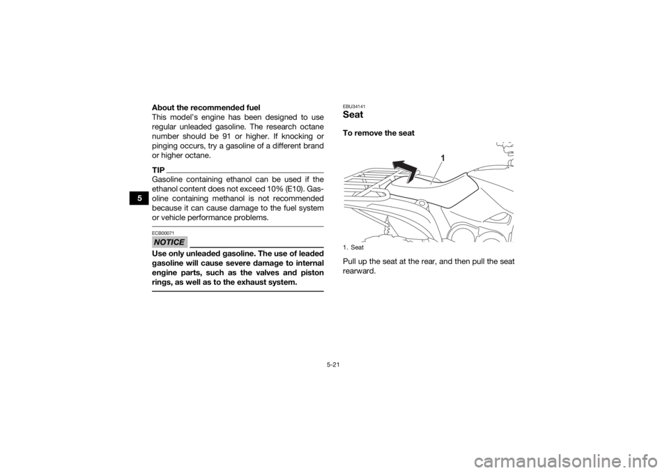
EBU34141SeatTo remove the seat
Pull up the seat at the rear, and then pull the seat
rearward.1. Seat
1
UBLT60E0.book Page 21 Tuesday, July 13, 2021 9:16 AM
Page 57 of 176
5-28
5
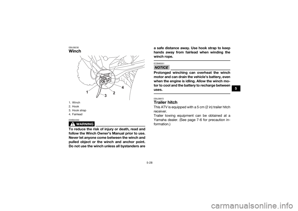
EBU39230Winch
WARNING
EWB04350To reduce the risk of injury or death, read and
follow the Winch Owner’s Manual prior to use.
Never let anyone come between the winch and
pulled object or the winch and anchor point.
Do not use the winch unless all bystanders area safe distance away. Use hook strap to keep
hands away from fairlead when winding the
winch rope.
NOTICEECBM0051Prolonged winching can overheat the winch
motor and can drain the vehicle’s battery, even
when the engine is idling. Allow the winch mo-
tor to cool and the battery to recharge between
uses. EBU28972Trailer hitch This ATV is equipped with a 5 cm (2 in) trailer hitch
receiver.
Trailer towing equipment can be obtained at a
Yamaha dealer. (See page 7-6 for precaution in- formation.)
1. Winch
2. Hook
3. Hook strap
4. Fairlead
1
3
2
4
UBLT60E0.book Page 28 Tuesday, July 13, 2021 9:16 AM
Page 59 of 176
5-30
5
TIPWhen using a winch or other electrical accesso-
ries, the power taken from the DC jack must be re-
duced accordingly. A 12-V accessory, such as a work light or radio
with the proper adapter, can be used when the
main switch is turned on. However, to prevent bat-
tery drain, use when the engine is running and the
headlights are turned off.1. Start the engine.
2. Turn the headlights off.
3. Make sure the accessory is powered off.
4. Open the auxiliary DC jack cap.
5. Insert the accessory power plug into the jack.
6. Turn the accessory on.TIP Turn off the accessory before plugging into/un-
plugging from the jack.
When the auxiliary DC jack is not being used,
cover it with the cap.
NOTICEECB00122If accessories are used with the engine off or
with the headlights on, the battery may dis-
charge to the point that the engine will not
start.
Do not use an automotive cigarette lighter or
other accessory with a plug that gets hot.
The DC jack may be damaged.
UBLT60E0.book Page 30 Tuesday, July 13, 2021 9:16 AM