light YAMAHA GRIZZLY 700 2022 Owner's Guide
[x] Cancel search | Manufacturer: YAMAHA, Model Year: 2022, Model line: GRIZZLY 700, Model: YAMAHA GRIZZLY 700 2022Pages: 176, PDF Size: 4.75 MB
Page 158 of 176

9-59
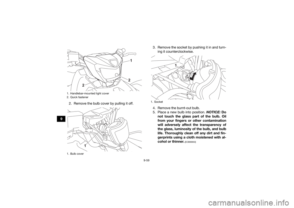
92. Remove the bulb cover by pulling it off. 3. Remove the socket by pushing it in and turn-
ing it counterclockwise.
4. Remove the burnt-out bulb.
5. Place a new bulb into position. NOTICE: Do
not touch the glass part of the bulb. Oil
from your fingers or other contamination
will adversely affect the transparency of
the glass, luminosity of the bulb, and bulb
life. Thoroughly clean off any dirt and fin-
gerprints using a cloth moistened with al-
cohol or thinner.
[ECB00653]
1. Handlebar-mounted light cover
2. Quick fastener
1. Bulb cover
1
2
2
1
1. Socket
1
UBLT60E0.book Page 59 Tuesday, July 13, 2021 9:16 AM
Page 159 of 176
![YAMAHA GRIZZLY 700 2022 Owners Guide 9-60
9
6. Install the socket by pushing it in and turning
it clockwise.
7. Install the bulb cover. NOTICE: Make sure
the bulb cover is securely fitted over the
socket and seated properly.
[ECB03320] YAMAHA GRIZZLY 700 2022 Owners Guide 9-60
9
6. Install the socket by pushing it in and turning
it clockwise.
7. Install the bulb cover. NOTICE: Make sure
the bulb cover is securely fitted over the
socket and seated properly.
[ECB03320]](/img/51/50437/w960_50437-158.png)
9-60
9
6. Install the socket by pushing it in and turning
it clockwise.
7. Install the bulb cover. NOTICE: Make sure
the bulb cover is securely fitted over the
socket and seated properly.
[ECB03320]
8. Install the handlebar-mounted light cover as shown, and then install the quick fasteners. 9. Adjust the handlebar-mounted light beam if
necessary.
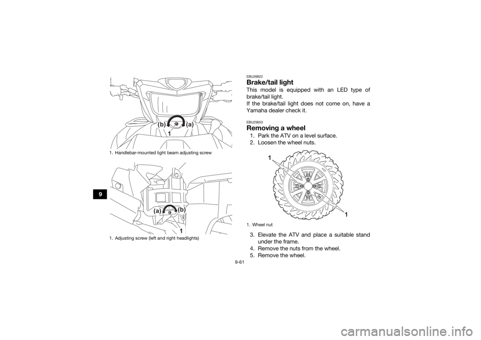
EBU25553Adjusting a headlight beamNOTICEECB00691It is advisable to have a Yamaha dealer make
this adjustment. To raise a headlight beam, turn the headlight
beam adjusting screw in direction (a).
To lower a headlight beam, turn the adjusting
screw in direction (b).
1. Do not touch the glass part of the bulb.
1
1. Handlebar-mounted light cover
1
UBLT60E0.book Page 60 Tuesday, July 13, 2021 9:16 AM
Page 160 of 176

9-61
9
EBU26922Brake/tail lightThis model is equipped with an LED type of
brake/tail light.
If the brake/tail light does not come on, have a
Yamaha dealer check it.EBU25653Removing a wheel1. Park the ATV on a level surface.
2. Loosen the wheel nuts.
3. Elevate the ATV and place a suitable stand under the frame.
4. Remove the nuts from the wheel.
5. Remove the wheel.
1. Handlebar-mounted light beam adjusting screw
1. Adjusting screw (left and right headlights)
(b)
(a)
1
(b)
(a)
1
1. Wheel nut
1
1
UBLT60E0.book Page 61 Tuesday, July 13, 2021 9:16 AM
Page 162 of 176

9-63
9
EBU25741TroubleshootingAlthough Yamaha ATVs receive a thorough in-
spection before shipment from the factory, trouble
may occur during operation. Any problem in the
fuel, compression, or ignition systems, for exam-
ple, can cause poor starting and loss of power.
The following troubleshooting charts represent
quick and easy procedures for checking these vi-
tal systems yourself. However, should your ATV
require any repair, take it to a Yamaha dealer,
whose skilled technicians have the necessary
tools, experience, and know-how to service the
ATV properly.
Use only genuine Yamaha replacement parts. Im-
itation parts may look like Yamaha parts, but they
are often inferior, have a shorter service life and
can lead to expensive repair bills.
WARNING
EWB02281Do not smoke when checking the fuel system.
Fuel can ignite or explode, causing severe inju-
ry or property damage. Make sure there are no
open flames or sparks in the area, including pi-
lot lights from water heaters or furnaces. UBLT60E0.book Page 63 Tuesday, July 13, 2021 9:16 AM
Page 166 of 176

10-2
108. If the headlight lens has fogged up, start the
engine and turn on the headlight to help re-
move the moisture.
EBU27264StorageShort-term
Always store your ATV in a cool, dry place and, if
necessary, protect it against dust with a porous
cover. NOTICE: Storing the ATV in a poorly ven-
tilated room or covering it with a tarp while it is
still wet, will allow water and humidity to seep
in and cause rust. To prevent corrosion, avoid
damp cellars, stables (because of the presence
of ammonia) and areas where strong chemi-
cals are stored.
[ECB00722]
Long-term
Before storing your ATV for several months: 1. Make any necessary repairs and perform all outstanding maintenance.
2. Follow all the instructions in the Cleaning sec- tion of this chapter. 3. Fill up the fuel tank and add fuel stabilizer (Fu-
el Med Rx if available), and then run the en-
gine for 5 minutes to distribute the treated
fuel.
4. Perform the following steps to protect the en- gine from internal corrosion.a. Remove the spark plug cap and spark plug.
b. Pour a teaspoonful of engine oil into the spark plug bore.
c. Install the spark plug cap onto the spark plug, and then place the spark plug on the
cylinder head so that the electrodes are
grounded. (This will limit sparking during
the next step.)
d. Turn the engine over several times with the starter. (This will coat the cylinder wall
with oil.)
e. Remove the spark plug cap from the spark plug, and then install the spark plug and
the spark plug cap.
5. Lubricate all control cables and the pivoting points of all levers and pedals.
Specified amount:
7.5 ml per liter of fuel (1 oz per gallon)UBLT60E0.book Page 2 Tuesday, July 13, 2021 9:16 AM
Page 170 of 176

11-3
11
Quantity:0.21 L (0.23 US qt, 0.19 Imp.qt)Coolant quantity:Radiator (including all routes):
1.99 L (2.10 US qt, 1.75 Imp.qt)
Coolant reservoir (up to the maximum level mark): 0.24 L (0.25 US qt, 0.21 Imp.qt)Fuel:Recommended fuel:
Regular unleaded gasoline (Gasohol [E10] acceptable)
Minimum research octane: 91
Fuel tank capacity: 18 L (4.8 US gal, 4.0 Imp.gal)
Fuel reserve amount:
4.0 L (1.06 US gal, 0.88 Imp.gal)Throttle body:ID mark:B4F1Front tire:Size:AT26 x 8-12 (BLT5, BLT8)
AT27 x 10-14 (BLTE)
Manufacturer/model: MAXXIS/MU01Y (BLTE)
MAXXIS/MU05Y (BLT5, BLT8)Rear tire:Size:AT26 x 10-12 (BLT5, BLT8)
AT27 x 10-14 (BLTE) Manufacturer/model:
MAXXIS/MU01Y (BLTE)
MAXXIS/MU06Y (BLT5, BLT8)
Front brake:Type:Hydraulic disc brakeRear brake:Type:Hydraulic disc brakeFront suspension:Type:
Double wishboneRear suspension:Type:Double wishboneElectrical system:System voltage:12 VBattery:Model:
YTX20L-BS
Voltage, capacity: 12 V, 18.0 AhLights:Headlight:
LED
Handlebar-mounted light: T15H, 35.0 W/36.5 W
Brake/tail light: LED
UBLT60E0.book Page 3 Tuesday, July 13, 2021 9:16 AM
Page 173 of 176

13-1
13
INDEX
AAccessories and loading ................................................ 7-5
Accessories, DC jack ................................................... 5-29
Air filter element, cleaning ........................................... 9-37
Axle boots .................................................................... 9-48BBattery ......................................................................... 9-52
Battery voltage warning light ......................................... 5-3
Brake fluid, changing ................................................... 9-45
Brake fluid level, checking ........................................... 9-44
Brake lever, front ......................................................... 5-17
Brake levers, checking and lubricating ........................ 9-49
Brake pads, checking the front and rear ..................... 9-43
Brake pedal and rear brake lever ................................. 5-17
Brake pedal, checking and lubricating ........................ 9-50
Brake pedal free play, adjusting .................................. 9-47
Brakes .......................................................................... 9-42
Brakes, front and rear .................................................... 6-4
Brake/tail light .............................................................. 9-61CCables, checking and lubricating ................................ 9-49
Carrier, front ................................................................. 5-26
Carrier, rear .................................................................. 5-26
Chassis fasteners .......................................................... 6-8
Cleaning ....................................................................... 10-1
Coolant .................................................................6-4, 9-29
Coolant temperature warning light ................................ 5-3DDifferential gear oil ................................................6-4, 9-27Drive select lever ......................................................... 5-18
Drive select lever and driving in reverse ........................ 7-2
EEmissions Certification label (for
Europe) .................... 12-1
Engine break-in .............................................................. 7-4
Engine oil ....................................................................... 6-4
Engine oil and oil filter cartridge .................................. 9-20
Engine stop switch ...................................................... 5-11
Engine trouble warning light .......................................... 5-3
EPS warning light .......................................................... 5-4FFinal gear oil ......................................................... 6-4, 9-25
Four-wheel drive/differential gear lock icon .................. 5-4
Four-wheel drive switch (On-Command 4WD) ............ 5-13
Front and rear brake lever free play, checking ............ 9-46
Fuel ....................................................................... 5-20, 6-4
Fuel tank cap ............................................................... 5-19
Fuses, replacing .......................................................... 9-56HHandlebar switches ..................................................... 5-11
Headlight beam, adjusting ........................................... 9-60
Headlight bulb, replacing ............................................. 9-58
High beam indicator light ............................................... 5-2
High-range indicator light .............................................. 5-2
Horn switch .................................................................. 5-12IIdentification numbers ................................................... 1-1
Indicator lights and warning lights ................................. 5-2
Instruments, lights and switches ................................... 6-8
UBLT60E0.book Page 1 Tuesday, July 13, 2021 9:16 AM
Page 174 of 176

13-2
13
LLabel locations ............................................................... 2-1
Light switch .................................................................. 5-12
Low-range indicator light ............................................... 5-2MMain switch .................................................................... 5-1
Maintenance chart, emission control system ................ 9-3
Maintenance chart, general maintenance and lubrication .................................................................... 9-5
Model label ..................................................................... 1-1
Multi-function display .....................................................5-5NNeutral indicator light .....................................................5-2OOn-Command drive switch “4WD/LOCK” ................... 5-14
Override switch ............................................................ 5-12
Owner’s Manuals and Tool Kit ....................................... 9-2PPanels, removing and installing ................................... 9-10
Park indicator light ......................................................... 5-2
Parking ........................................................................... 7-4
Parking on a slope ......................................................... 7-5
Part locations ................................................................. 4-1RRear knuckle pivots, lubricating ................................... 9-51
Reverse indicator light ................................................... 5-2
Riding your ATV ............................................................. 8-1SSafety information .......................................................... 3-1
Seat .............................................................................. 5-21 Shock absorber assemblies, adjusting the front and
rear ............................................................................. 5-26
Spark arrester, cleaning ............................................... 9-40
Spark plug, checking ................................................... 9-18
Specifications .............................................................. 11-1
Speed limiter ................................................................ 5-16
Stabilizer bushes, checking ......................................... 9-51
Starting the engine ......................................................... 7-1
Start switch .................................................................. 5-12
Steering shaft, lubricating ............................................ 9-52
Storage ........................................................................ 10-2
Storage compartments ................................................ 5-22
TThrottle lever ........................................................ 5-16, 6-5
Throttle lever free play, adjusting ................................. 9-42
Tires ............................................................................... 6-5
Trailer hitch .................................................................. 5-28
Troubleshooting ........................................................... 9-63
Troubleshooting charts ................................................ 9-64VValve clearance ............................................................ 9-42
V-belt case drain plug .................................................. 9-41
Vehicle identification number ......................................... 1-1WWheel hub bearings, checking ..................................... 9-51
Wheel, installing ........................................................... 9-62
Wheel, removing .......................................................... 9-61
Winch ........................................................................... 5-28
Winch switch ................................................................ 5-12YYamalube ..................................................................... 9-24
UBLT60E0.book Page 2 Tuesday, July 13, 2021 9:16 AM