lock YAMAHA MAJESTY 250 2001 User Guide
[x] Cancel search | Manufacturer: YAMAHA, Model Year: 2001, Model line: MAJESTY 250, Model: YAMAHA MAJESTY 250 2001Pages: 106, PDF Size: 1.65 MB
Page 77 of 106
2.Remove the blown fuse, and
then install a new fuse of the
specified amperage.
EC000103
cCDo not use a fuse of a higher
amperage rating than recommend-
ed to avoid causing extensive
damage to the electrical system
and possibly a fire.3.Turn the key to ÒONÓ and turn on
the electrical circuit in question to
check if the device operates.
6-33
PERIODIC MAINTENANCE AND MINOR REPAIR
1
2
3
4
56
7
8
94.If the fuse immediately blows
again, have a Yamaha dealer
check the electrical system.
Specified fuses:
Main fuse:30 A
Clock fuse:10 A
Radiator fan fuse:4 A
Ignition fuse:7.5 A
Headlight fuse:15 A
Signaling system fuse:15 A
4
5
67
1
32
78
EAU03622
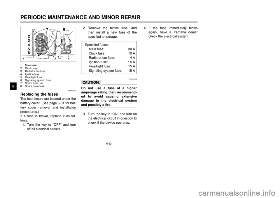
Replacing the fusesThe fuse boxes are located under the
battery cover. (See page 6-31 for bat-
tery cover removal and installation
procedures.)
If a fuse is blown, replace it as fol-
lows.
1.Turn the key to ÒOFFÓ and turn
off all electrical circuits.1.Main fuse
2.Clock fuse
3.Radiator fan fuse
4.Ignition fuse
5.Headlight fuse
6.Signaling system fuse
7.Spare fuse (´4)
8.Spare main fuse
5GM-9-E1(No ABS) 9/27/00 2:18 PM Page 76
Page 80 of 106
6-36
PERIODIC MAINTENANCE AND MINOR REPAIR
1
2
3
4
56
7
8
9
1
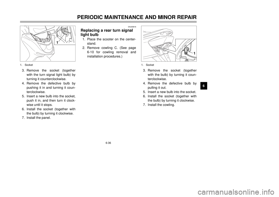
3.Remove the socket (together
with the turn signal light bulb) by
turning it counterclockwise.
4.Remove the defective bulb by
pushing it in and turning it coun-
terclockwise.
5.Insert a new bulb into the socket,
push it in, and then turn it clock-
wise until it stops.
6.Install the socket (together with
the bulb) by turning it clockwise.
7.Install the panel.1.Socket
EAU03618
Replacing a rear turn signal
light bulb1.Place the scooter on the center-
stand.
2.Remove cowling C. (See page
6-10 for cowling removal and
installation procedures.)
1
1.Socket3.Remove the socket (together
with the bulb) by turning it coun-
terclockwise.
4.Remove the defective bulb by
pulling it out.
5.Insert a new bulb into the socket.
6.Install the socket (together with
the bulb) by turning it clockwise.
7.Install the cowling.
5GM-9-E1(No ABS) 9/27/00 2:18 PM Page 79
Page 81 of 106
6-37
PERIODIC MAINTENANCE AND MINOR REPAIR
1
2
3
4
56
7
8
9
EAU03619
Replacing a tail/brake light
bulb1.Place the scooter on the center-
stand.
2.Remove cowling C. (See page
6-10 for cowling removal and
installation procedures.)
EAU03621
Replacing the license plate
light bulb1.Place the scooter on the center-
stand.
2.Remove cowling C. (See page
6-10 for cowling removal and
installation procedures.)
1
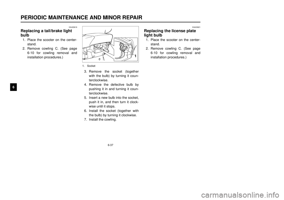
1.Socket3.Remove the socket (together
with the bulb) by turning it coun-
terclockwise.
4.Remove the defective bulb by
pushing it in and turning it coun-
terclockwise.
5.Insert a new bulb into the socket,
push it in, and then turn it clock-
wise until it stops.
6.Install the socket (together with
the bulb) by turning it clockwise.
7.Install the cowling.
5GM-9-E1(No ABS) 9/27/00 2:18 PM Page 80
Page 84 of 106
6-40
PERIODIC MAINTENANCE AND MINOR REPAIR
1
2
3
4
56
7
8
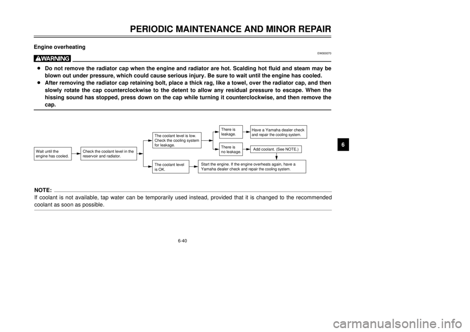
9 Engine overheating
EW000070
w8Do not remove the radiator cap when the engine and radiator are hot. Scalding hot fluid and steam may be
blown out under pressure, which could cause serious injury. Be sure to wait until the engine has cooled.
8After removing the radiator cap retaining bolt, place a thick rag, like a towel, over the radiator cap, and then
slowly rotate the cap counterclockwise to the detent to allow any residual pressure to escape. When the
hissing sound has stopped, press down on the cap while turning it counterclockwise, and then remove the
cap.Wait until the
engine has cooled.
Check the coolant level in the
reservoir and radiator.
The coolant level
is OK.The coolant level is low.
Check the cooling system
for leakage.
Have a Yamaha dealer checkand repair the cooling system.Add coolant. (See NOTE.)
Start the engine. If the engine overheats again,
have a
Yamaha dealer check
and repair the cooling system.
There is
leakage.
There is
no leakage.
NOTE:
If coolant is not available, tap water can be temporarily used instead, provided that it is changed to the recommended
coolant as soon as possible.
5GM-9-E1(No ABS) 9/27/00 2:18 PM Page 83
Page 96 of 106

8-4
SPECIFICATIONS
1
2
3
4
5
6
78
9
Auxiliary light12 V, 5 W ´1
License plate light12 V, 5 W ´1
Meter lighting12 V, 1.7 W ´3
High beam indicator light12 V, 1.7 W ´1
Turn indicator light12 V, 3.4 W ´2
Oil change indicator light12 V, 1.7 W ´1
Fuses
Main fuse30 A
Headlight fuse15 A
Signaling system fuse15 A
Ignition fuse7.5 A
Radiator fan fuse4 A
Clock fuse (back up)10 A
5GM-9-E1(No ABS) 9/27/00 2:18 PM Page 95
Page 101 of 106
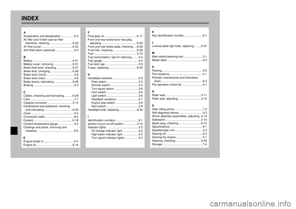
INDEX
F
Final gear oil..........................................6-17
Front and rear brake lever free play,
adjusting.............................................6-25
Front and rear brake pads, checking.....6-26
Front fork, checking...............................6-29
Fuel.......................................................3-10
Fuel consumption, tips for reducing........5-4
Fuel gauge..............................................3-4
Fuel tank cap...........................................3-9
Fuses, replacing....................................6-33
H
Handlebar switches.................................3-5
Pass switch.........................................3-5
Dimmer switch....................................3-5
Turn signal switch...............................3-6
Horn switch.........................................3-6
Light switch.........................................3-6
Headlight variations............................3-7
Engine stop switch..............................3-8
Start switch.........................................3-8
Headlight bulb, replacing.......................6-34
I
Identification numbers.............................9-1
Ignition circuit cut-off system.................3-15
Indicator lights.........................................3-2
Oil change indicator light....................3-2
High beam indicator light....................3-2
Turn signal indicator lights..................3-2
K
Key identification number........................9-1
L
License plate light bulb, replacing.........6-37
M
Main switch/steering lock........................3-1
Model label..............................................9-2
P
Parking....................................................5-5
Part locations...........................................2-1
Periodic maintenance and lubrication
chart......................................................6-3
Pre-operation check list...........................4-1
R
Rider seat..............................................3-11
Rider seat, adjusting..............................3-12
S
Safe-riding points....................................1-2
Self-diagnosis device..............................3-3
Shock absorber assemblies, adjusting..3-14
Sidestand..............................................3-15
Spark plug, checking.............................6-12
Specifications..........................................8-1
Speedometer unit....................................3-3
Starting off...............................................5-2
Starting the engine..................................5-1
Steering, checking.................................6-30
Storage....................................................7-4
A
Acceleration and deceleration.................5-3
Air filter and V-belt case air filter
elements, cleaning..............................6-20
Air flow louver........................................6-22
Anti-theft alarm (optional)........................3-4
B
Battery...................................................6-31
Battery cover, removing........................6-31
Brake fluid level, checking.....................6-27
Brake fluid, changing.............................6-28
Brake lever (front)....................................3-8
Brake lever (rear)....................................3-8
Brake levers, lubricating........................6-28
Braking....................................................5-3
C
Cables, checking and lubricating...........6-28
Care.........................................................7-1
Catalytic converter.................................3-10
Centerstand and sidestand, checking
and lubricating....................................6-29
Clock.......................................................3-5
Conversion table.....................................8-5
Coolant..................................................6-18
Coolant temperature gauge.....................3-4
Cowlings and panel, removing and
installing................................................6-6
E
Engine break-in.......................................5-4
Engine oil...............................................6-14
5GM-9-E1(No ABS) 9/27/00 2:18 PM Page 100