fuel YAMAHA MAJESTY 250 2002 Owners Manual
[x] Cancel search | Manufacturer: YAMAHA, Model Year: 2002, Model line: MAJESTY 250, Model: YAMAHA MAJESTY 250 2002Pages: 114, PDF Size: 1.96 MB
Page 13 of 114
2-1
EAU00026
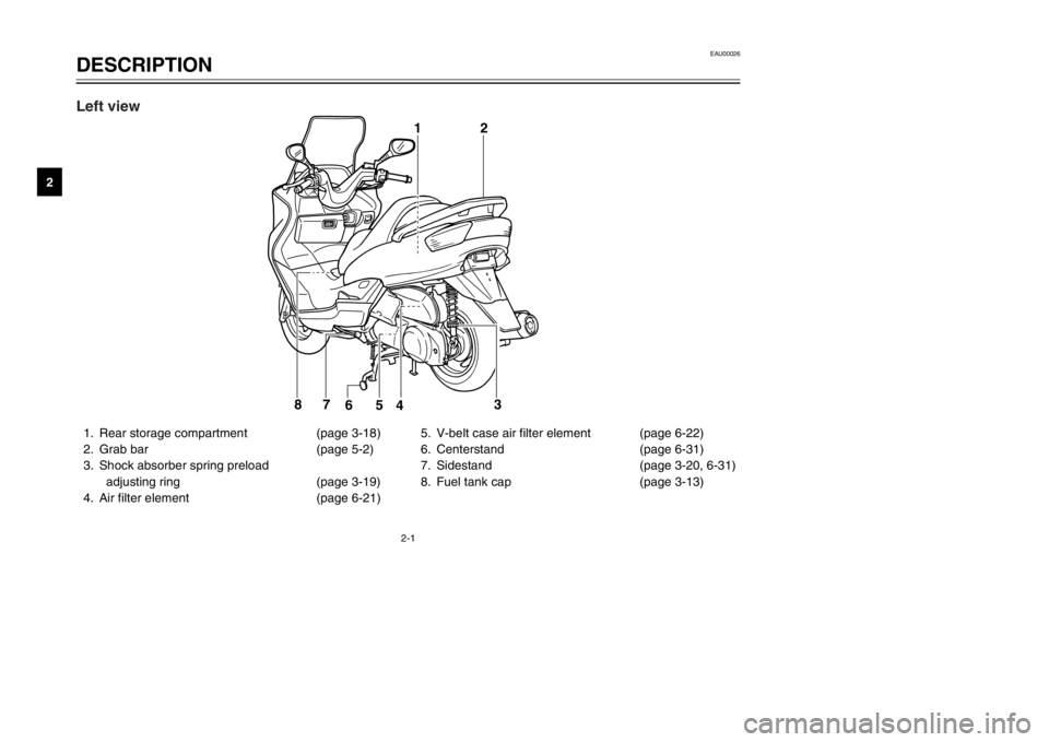
DESCRIPTIONPart locations
2
1. Rear storage compartment (page 3-18)
2. Grab bar (page 5-2)
3. Shock absorber spring preload
adjusting ring (page 3-19)
4. Air filter element (page 6-21)5. V-belt case air filter element (page 6-22)
6. Centerstand (page 6-31)
7. Sidestand (page 3-20, 6-31)
8. Fuel tank cap (page 3-13)
12
3
4 5 6 7
8
Left view
5SJ-28199-E0 1/24/02 6:14 PM Page 12
Page 15 of 114
2-3
EAU00026
DESCRIPTION
2
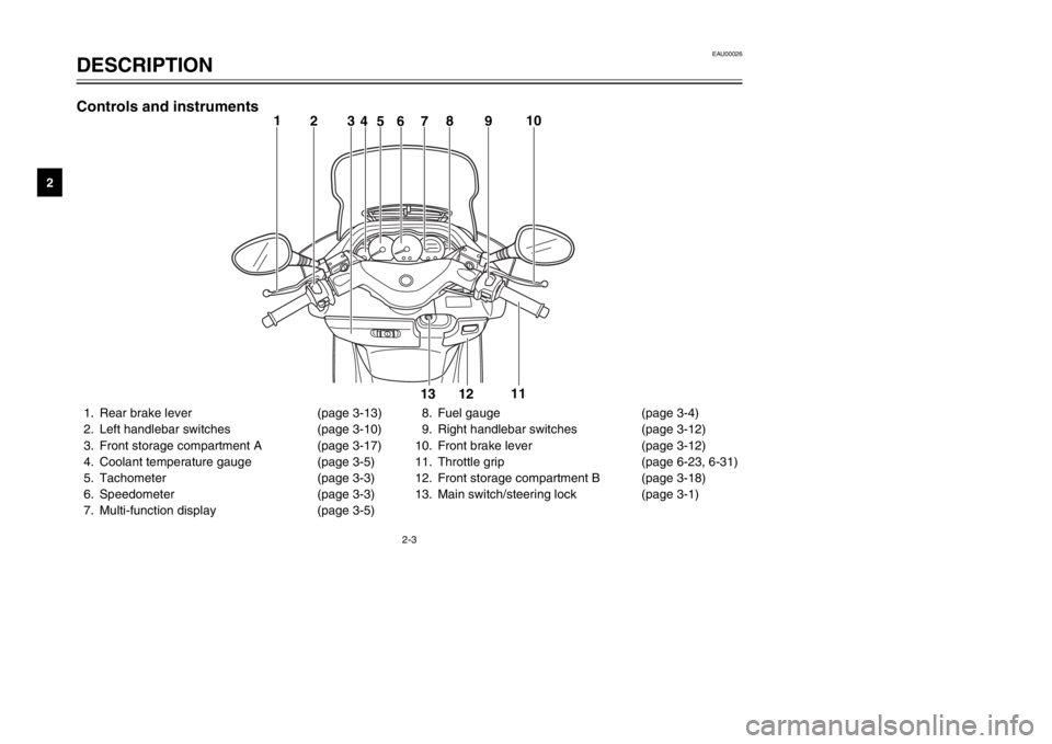
1. Rear brake lever (page 3-13)
2. Left handlebar switches (page 3-10)
3. Front storage compartment A (page 3-17)
4. Coolant temperature gauge (page 3-5)
5. Tachometer (page 3-3)
6. Speedometer (page 3-3)
7. Multi-function display (page 3-5)8. Fuel gauge (page 3-4)
9. Right handlebar switches (page 3-12)
10. Front brake lever (page 3-12)
11. Throttle grip (page 6-23, 6-31)
12. Front storage compartment B (page 3-18)
13. Main switch/steering lock (page 3-1)
1
23
46578910
11
12 13
Controls and instruments
5SJ-28199-E0 1/24/02 6:14 PM Page 14
Page 16 of 114
INSTRUMENT AND CONTROL FUNCTIONSMain switch/steering lock ...................................................................3-1
Indicator lights ...................................................................................3-2
Speedometer .....................................................................................3-3
Tachometer .......................................................................................3-3
Fuel gauge .........................................................................................3-4
Coolant temperature gauge ...............................................................3-5
Multi-function display .........................................................................3-5
Anti-theft alarm (optional) ..................................................................3-9
Handlebar switches .........................................................................3-10
Front brake lever .............................................................................3-12
Rear brake lever ..............................................................................3-13
Fuel tank cap ...................................................................................3-13
Fuel ..................................................................................................3-14
Catalytic converter ...........................................................................3-15
Rider seat ........................................................................................3-16
Adjusting the rider seat ....................................................................3-17
Storage compartments ....................................................................3-17
Adjusting the shock absorber assemblies .......................................3-19
Sidestand .........................................................................................3-20
Ignition circuit cut-off system ...........................................................3-21
3
5SJ-28199-E0 1/24/02 6:14 PM Page 15
Page 20 of 114
3-4
INSTRUMENT AND CONTROL FUNCTIONS
3
EAU00110
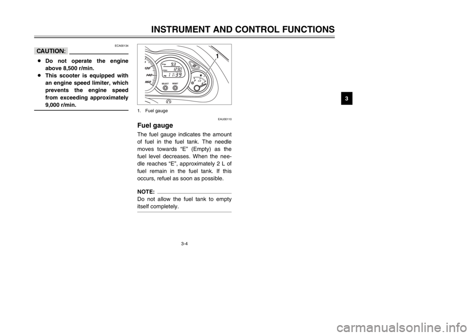
Fuel gaugeFuel gaugeThe fuel gauge indicates the amount
of fuel in the fuel tank. The needle
moves towards “E” (Empty) as the
fuel level decreases. When the nee-
dle reaches “E”, approximately 2 L of
fuel remain in the fuel tank. If this
occurs, refuel as soon as possible.NOTE:
Do not allow the fuel tank to empty
itself completely.
1
1. Fuel gauge
ECA00134
cC8Do not operate the engine
above 8,500 r/min.
8This scooter is equipped with
an engine speed limiter, which
prevents the engine speed
from exceeding approximately
9,000 r/min.
5SJ-28199-E0 1/24/02 6:14 PM Page 19
Page 21 of 114
3-5
INSTRUMENT AND CONTROL FUNCTIONS
3
EAU03124
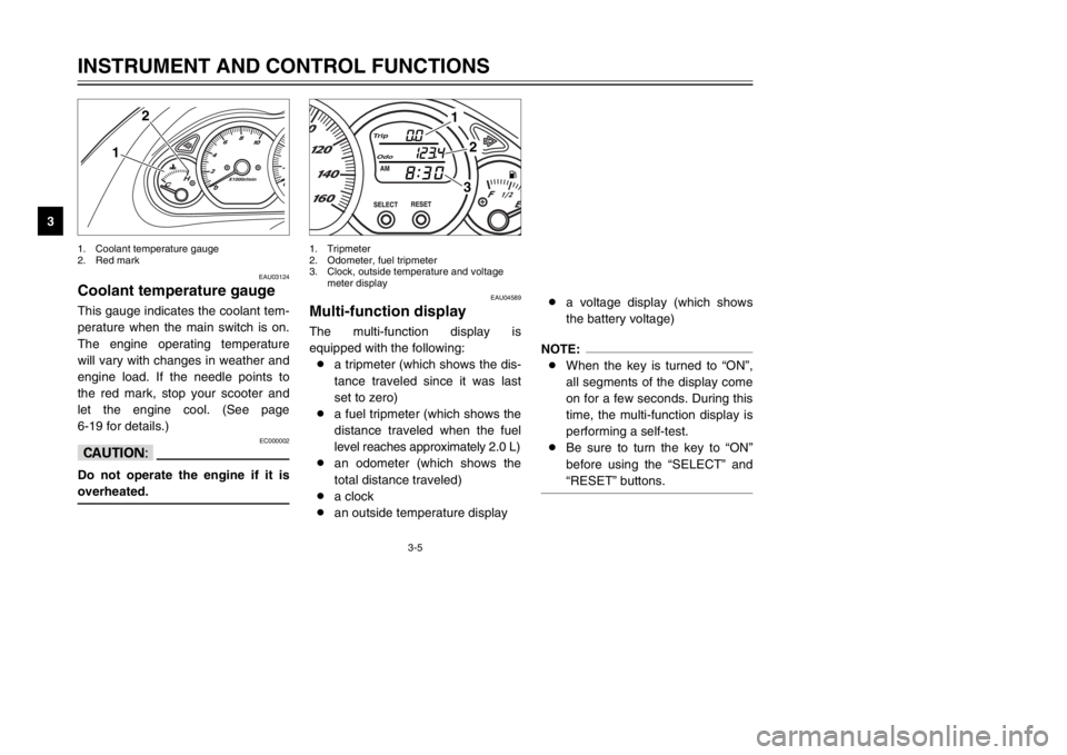
Coolant temperature gaugeCoolant temperature gaugeThis gauge indicates the coolant tem-
perature when the main switch is on.
The engine operating temperature
will vary with changes in weather and
engine load. If the needle points to
the red mark, stop your scooter and
let the engine cool. (See page
6-19 for details.)
EC000002
cCDo not operate the engine if it is
overheated.
1
2
1. Coolant temperature gauge
2. Red mark
EAU04589
Multi-function displayDisplay, multi-functionThe multi-function display is
equipped with the following:
8a tripmeter (which shows the dis-
tance traveled since it was last
set to zero)
8a fuel tripmeter (which shows the
distance traveled when the fuel
level reaches approximately 2.0 L)
8an odometer (which shows the
total distance traveled)
8a clock
8an outside temperature display8a voltage display (which shows
the battery voltage)
NOTE:
8When the key is turned to “ON”,
all segments of the display come
on for a few seconds. During this
time, the multi-function display is
performing a self-test.
8Be sure to turn the key to “ON”
before using the “SELECT” and
“RESET” buttons.
1
23
1. Tripmeter
2. Odometer, fuel tripmeter
3. Clock, outside temperature and voltage
meter display
5SJ-28199-E0 1/24/02 6:14 PM Page 20
Page 22 of 114
3-6
INSTRUMENT AND CONTROL FUNCTIONS
3
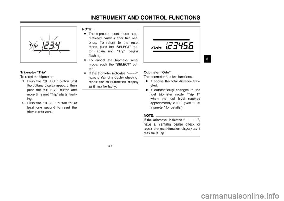
Tripmeter “Trip”
To reset the tripmeter:
1. Push the “SELECT” button until
the voltage display appears, then
push the “SELECT” button one
more time and “Trip” starts flash-
ing.
2. Push the “RESET” button for at
least one second to reset the
tripmeter to zero.
NOTE:
8The tripmeter reset mode auto-
matically cancels after five sec-
onds. To return to the reset
mode, push the “SELECT” but-
ton again until “Trip” begins
flashing.
8To cancel the tripmeter reset
mode, push the “SELECT” but-
ton.
8If the tripmeter indicates “––––”,
have a Yamaha dealer check or
repair the multi-function display
as it may be faulty.
Odometer “Odo”
The odometer has two functions.
8It shows the total distance trav-
eled.
8It automatically changes to the
fuel tripmeter mode “Trip F”
when the fuel level reaches
approximately 2.0 L. (See “Fuel
tripmeter” for details.)NOTE:
If the odometer indicates “––––––”,
have a Yamaha dealer check or
repair the multi-function display as it
may be faulty.
5SJ-28199-E0 1/24/02 6:14 PM Page 21
Page 23 of 114

3-7
INSTRUMENT AND CONTROL FUNCTIONS
3
Fuel tripmeter “Trip F”
When the fuel level reaches approxi-
mately 2.0 L, the odometer display
automatically changes to the fuel trip-
meter mode “Trip F” and starts count-
ing the distance traveled from that
point. After refueling and traveling
5 km, the odometer display returns to
“Odo”.
To return to the odometer mode
before refueling, push the “SELECT”
button until “Trip F” begins flashing
(“Trip F” will only flash for five sec-
onds). While “Trip F” is flashing, push
the “RESET” button for at least one
second and the display will return to
the odometer mode. From that time,
both “Trip” and “Odo” are displayed
until you refuel and travel 5 km.NOTE:
The display cannot be changed back
to “Trip F” after pushing the “RESET”
button.
Clock
To set the clock1. Push the “SELECT” button until
the clock is displayed.
2. Push the “SELECT” button and
“RESET” button together for at
least two seconds.
5SJ-28199-E0 1/24/02 6:14 PM Page 22
Page 29 of 114
3-13
INSTRUMENT AND CONTROL FUNCTIONS
3
EAU00163
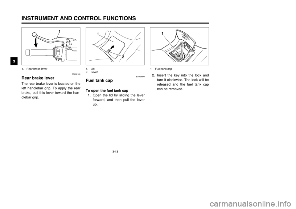
Rear brake leverBrake lever, rearThe rear brake lever is located on the
left handlebar grip. To apply the rear
brake, pull this lever toward the han-
dlebar grip.
1
1. Rear brake lever
2. Insert the key into the lock and
turn it clockwise. The lock will be
released and the fuel tank cap
can be removed.
1
1. Fuel tank cap
EAU03090
Fuel tank capFuel tank capTo open the fuel tank cap
1. Open the lid by sliding the lever
forward, and then pull the lever
up.
1
2
1. Lid
2. Lever
5SJ-28199-E0 1/24/02 6:14 PM Page 28
Page 30 of 114
3-14
INSTRUMENT AND CONTROL FUNCTIONS
3
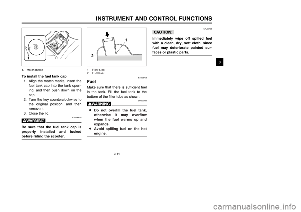
To install the fuel tank cap
1. Align the match marks, insert the
fuel tank cap into the tank open-
ing, and then push down on the
cap.
2. Turn the key counterclockwise to
the original position, and then
remove it.
3. Close the lid.
EWA00028
wBe sure that the fuel tank cap is
properly installed and locked
before riding the scooter.
1
1. Match marks
EAU03753
FuelFuelMake sure that there is sufficient fuel
in the tank. Fill the fuel tank to the
bottom of the filler tube as shown.
EW000130
w8 8
Do not overfill the fuel tank,
otherwise it may overflow
when the fuel warms up and
expands.
8 8
Avoid spilling fuel on the hot
engine.
1
2
1. Filler tube
2. Fuel level
EAU00185
cCImmediately wipe off spilled fuel
with a clean, dry, soft cloth, since
fuel may deteriorate painted sur-
faces or plastic parts.
5SJ-28199-E0 1/24/02 6:14 PM Page 29
Page 31 of 114
3-15
INSTRUMENT AND CONTROL FUNCTIONS
3
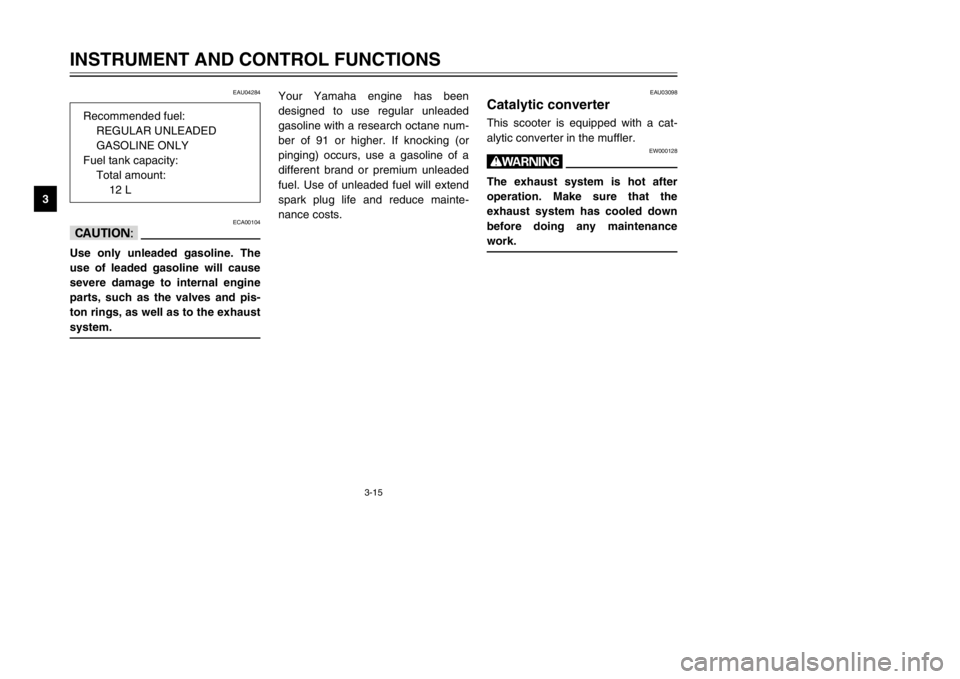
EAU04284
ECA00104
cCUse only unleaded gasoline. The
use of leaded gasoline will cause
severe damage to internal engine
parts, such as the valves and pis-
ton rings, as well as to the exhaust
system.
EAU03098
Catalytic converterCatalytic converterThis scooter is equipped with a cat-
alytic converter in the muffler.
EW000128
wThe exhaust system is hot after
operation. Make sure that the
exhaust system has cooled down
before doing any maintenance
work.
Your Yamaha engine has been
designed to use regular unleaded
gasoline with a research octane num-
ber of 91 or higher. If knocking (or
pinging) occurs, use a gasoline of a
different brand or premium unleaded
fuel. Use of unleaded fuel will extend
spark plug life and reduce mainte-
nance costs. Recommended fuel:
REGULAR UNLEADED
GASOLINE ONLY
Fuel tank capacity:
Total amount:
12 L
5SJ-28199-E0 1/24/02 6:14 PM Page 30