light YAMAHA MAJESTY 250 2002 Owners Manual
[x] Cancel search | Manufacturer: YAMAHA, Model Year: 2002, Model line: MAJESTY 250, Model: YAMAHA MAJESTY 250 2002Pages: 114, PDF Size: 1.96 MB
Page 14 of 114
2-2
DESCRIPTION
2
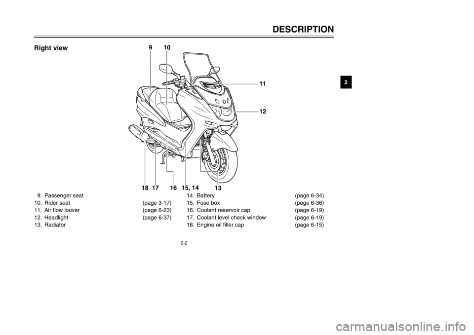
9. Passenger seat
10. Rider seat (page 3-17)
11. Air flow louver (page 6-23)
12. Headlight (page 6-37)
13. Radiator 14. Battery (page 6-34)
15. Fuse box (page 6-36)
16. Coolant reservoir cap (page 6-19)
17. Coolant level check window (page 6-19)
18. Engine oil filler cap (page 6-15)
11
12
13 16 17
1815, 14
10
9
Right view
5SJ-28199-E0 1/24/02 6:14 PM Page 13
Page 16 of 114
INSTRUMENT AND CONTROL FUNCTIONSMain switch/steering lock ...................................................................3-1
Indicator lights ...................................................................................3-2
Speedometer .....................................................................................3-3
Tachometer .......................................................................................3-3
Fuel gauge .........................................................................................3-4
Coolant temperature gauge ...............................................................3-5
Multi-function display .........................................................................3-5
Anti-theft alarm (optional) ..................................................................3-9
Handlebar switches .........................................................................3-10
Front brake lever .............................................................................3-12
Rear brake lever ..............................................................................3-13
Fuel tank cap ...................................................................................3-13
Fuel ..................................................................................................3-14
Catalytic converter ...........................................................................3-15
Rider seat ........................................................................................3-16
Adjusting the rider seat ....................................................................3-17
Storage compartments ....................................................................3-17
Adjusting the shock absorber assemblies .......................................3-19
Sidestand .........................................................................................3-20
Ignition circuit cut-off system ...........................................................3-21
3
5SJ-28199-E0 1/24/02 6:14 PM Page 15
Page 17 of 114

3-1
EAU00029
Main switch/steering lockMain switch/steering lockThe main switch/steering lock con-
trols the ignition and lighting systems,
and is used to lock the steering. The
various positions are described
below.
EAU04580
ON
All electrical circuits are supplied with
power, the meter lighting, taillight,
license plate light and auxiliary light
come on, and the engine can be
started. The key cannot be removed.
EAU00027
INSTRUMENT AND CONTROL FUNCTIONS
3
IGNITION
P
LOCK
ON
OFF
OPENPUSHPUSH
NOTE:
The headlight comes on automatical-
ly when the engine is started and
stays on until the key is turned to
“OFF” or the sidestand is moved
down.
EAU00038
OFF
All electrical systems are off. The key
can be removed.
EAU00040
LOCK
The steering is locked, and all electri-
cal systems are off. The key can be
removed.To lock the steering
1. Turn the handlebars all the way
to the left.
2. Push the key in from the “OFF”
position, and then turn it to
“LOCK” while still pushing it.
3. Remove the key.
To unlock the steeringPush the key in, and then turn it to
“OFF” while still pushing it.
EW000016
wNever turn the key to “OFF” or
“LOCK” while the scooter is mov-
ing, otherwise the electrical sys-
tems will be switched off, which
may result in loss of control or an
accident. Make sure that the scoot-
er is stopped before turning the
key to “OFF” or “LOCK”.
5SJ-28199-E0 1/24/02 6:14 PM Page 16
Page 18 of 114
3-2
INSTRUMENT AND CONTROL FUNCTIONS
3
EAU03733
.
(Parking)
The steering is locked, and the tail-
light, license light and auxiliary light
are on, but all other electrical sys-
tems are off. The key can be
removed.
To turn the main switch to “
.
”:
1. Turn the key to “LOCK”.
2. Slightly turn the key counter-
clockwise until it stops.
3. While still turning the key coun-
terclockwise, push it in until it
snaps into place.
ECA00043
cCDo not use the parking position for
an extended length of time, other-
wise the battery may discharge.
EAU03734
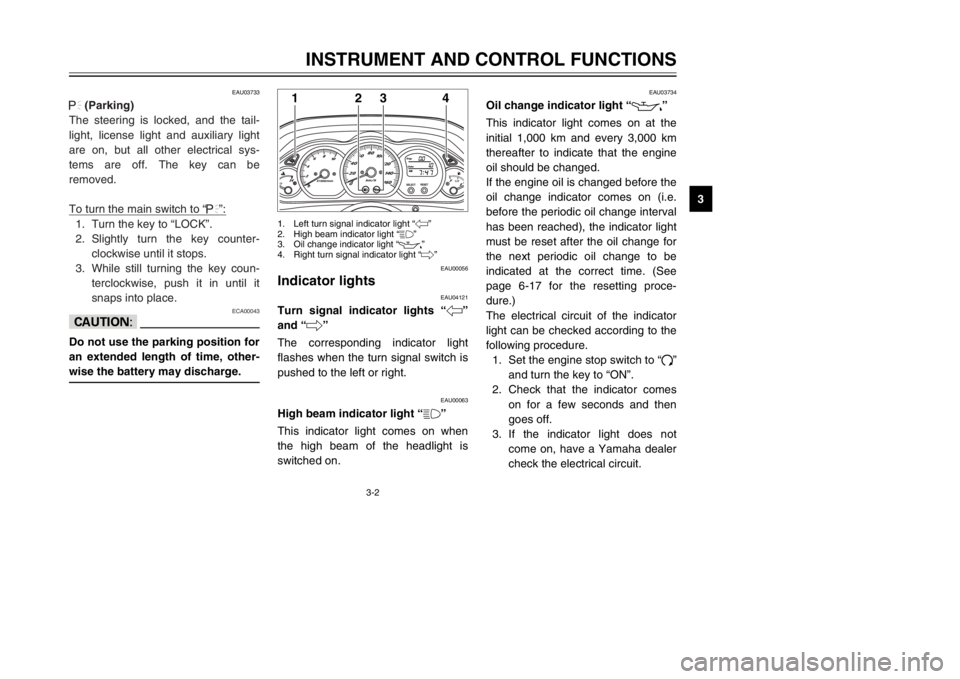
Oil change indicator light “
7
”
Oil change indicator lightThis indicator light comes on at the
initial 1,000 km and every 3,000 km
thereafter to indicate that the engine
oil should be changed.
If the engine oil is changed before the
oil change indicator comes on (i.e.
before the periodic oil change interval
has been reached), the indicator light
must be reset after the oil change for
the next periodic oil change to be
indicated at the correct time. (See
page 6-17 for the resetting proce-
dure.)
The electrical circuit of the indicator
light can be checked according to the
following procedure.
1. Set the engine stop switch to “#”
and turn the key to “ON”.
2. Check that the indicator comes
on for a few seconds and then
goes off.
3. If the indicator light does not
come on, have a Yamaha dealer
check the electrical circuit.
EAU00056
Indicator lightsIndicator lights
EAU04121
Turn signal indicator lights “4”
and “6”Turn signal indicator lightsThe corresponding indicator light
flashes when the turn signal switch is
pushed to the left or right.
EAU00063
High beam indicator light “&”High beam indicator lightThis indicator light comes on when
the high beam of the headlight is
switched on.
1
2
3
4
1. Left turn signal indicator light “4”
2. High beam indicator light “&”
3. Oil change indicator light “
7
”
4. Right turn signal indicator light “6”
5SJ-28199-E0 1/24/02 6:14 PM Page 17
Page 19 of 114

3-3
NOTE:
The oil change indicator light may
flash when the engine is revved with
the scooter on the centerstand, but
this does not indicate a malfunction.INSTRUMENT AND CONTROL FUNCTIONS
3
EAU04582
TachometerTachometerThe electric tachometer allows the
rider to monitor the engine speed and
keep it within the ideal power range.
When the key is turned to “ON”, the
tachometer needle will move to the
10,000 r/min and back to zero r/min
in order to test the electrical circuit.
1
1. Tachometer
EAU04581
SpeedometerSpeedometerThe speedometer shows the riding
speed.
When the key is turned to “ON”, the
speedometer needle will move to
160 km/h and back to zero in order to
test the electrical circuit.
1
1. Speedometer
5SJ-28199-E0 1/24/02 6:14 PM Page 18
Page 26 of 114
3-10
INSTRUMENT AND CONTROL FUNCTIONS
3
EAU00118
Handlebar switchesHandlebar switches
EAU00120
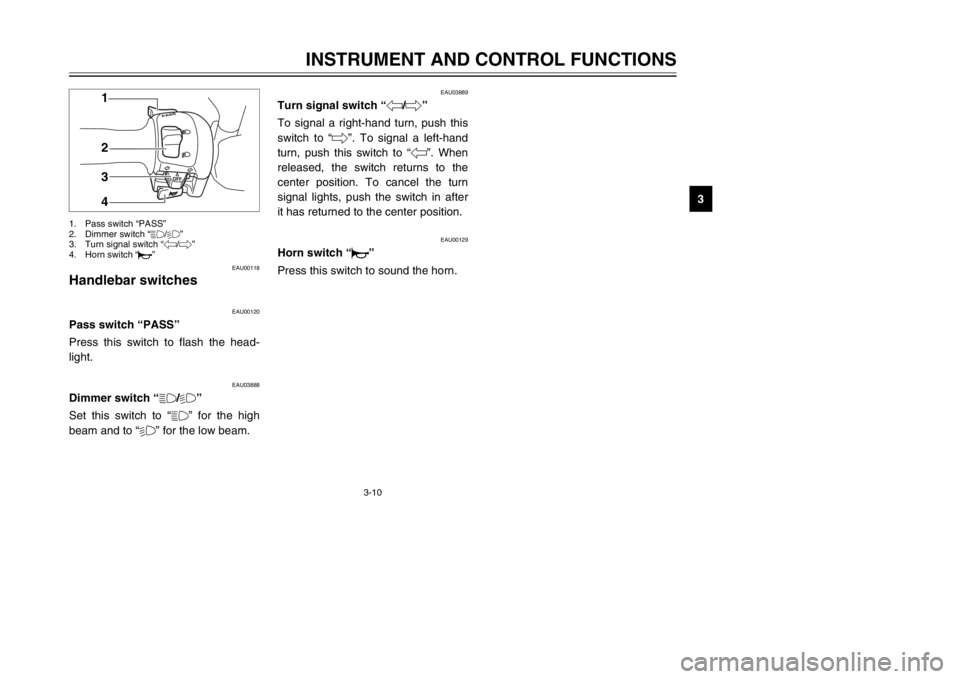
Pass switch “PASS”Pass switchPress this switch to flash the head-
light.
EAU03888
Dimmer switch “&/%”Dimmer switchSet this switch to “&” for the high
beam and to “%” for the low beam.
1
2
3
4
1. Pass switch “PASS”
2. Dimmer switch “&/%”
3. Turn signal switch “4/6”
4. Horn switch “*”
EAU03889
Turn signal switch “4/6”Turn signal switchTo signal a right-hand turn, push this
switch to “6”. To signal a left-hand
turn, push this switch to “4”. When
released, the switch returns to the
center position. To cancel the turn
signal lights, push the switch in after
it has returned to the center position.
EAU00129
Horn switch “*”Horn switchPress this switch to sound the horn.
5SJ-28199-E0 1/24/02 6:14 PM Page 25
Page 27 of 114

3-11
INSTRUMENT AND CONTROL FUNCTIONS
3
EAU00136
Headlight variationsHeadlight variationsNOTE:
Right and left are defined as seen when standing in front of the scooter.1
2
%
% &
&
Left Right AuxBulb to be used
Destination2
1
1
31
3
2
1
Halogen
bulb
Halogen
bulbGermany, Belgium, Switzerland, Spain
France, Greece, Italy, Netherlands,
Norway, Portugal, Sweden
England 3: High beam light on2: Low beam light on
'
: Auxiliary light on1: Light off
12V
55W
12V
60/55W
12V
60/55W
12V
55W '
'
'
'
5SJ-28199-E0 1/24/02 6:14 PM Page 26
Page 35 of 114
3-19
INSTRUMENT AND CONTROL FUNCTIONS
3
ECA00051
cCDo not leave the rider seat open
for an extended period of time,
otherwise the light may cause the
battery to discharge.
EWA00035
wDo not exceed the following load-
ing limits:
8 8
Front storage compartment A:
2 kg
8 8
Rear storage compartment:
5 kg
8 8
Maximum load for the vehicle:
185 kg
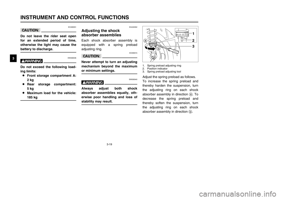
Adjust the spring preload as follows.
To increase the spring preload and
thereby harden the suspension, turn
the adjusting ring on each shock
absorber assembly in direction a. To
decrease the spring preload and
thereby soften the suspension, turn
the adjusting ring on each shock
absorber assembly in direction b.a
b1
23
1. Spring preload adjusting ring
2. Position indicator
3. Spring preload adjusting tool
EAU04552
Adjusting the shock
absorber assembliesShock absorber assemblies, adjustingEach shock absorber assembly is
equipped with a spring preload
adjusting ring.
EC000015
cCNever attempt to turn an adjusting
mechanism beyond the maximum
or minimum settings.
EW000040
wAlways adjust both shock
absorber assemblies equally, oth-
erwise poor handling and loss of
stability may result.
5SJ-28199-E0 1/24/02 6:14 PM Page 34
Page 37 of 114

3-21
INSTRUMENT AND CONTROL FUNCTIONS
3
EAU00337
Ignition circuit cut-off
systemIgnition circuit cut-off systemThe ignition circuit cut-off system
(comprising the sidestand switch and
brake light switches) has the follow-
ing functions.
8It prevents starting when the
sidestand is up, but neither brake
is applied.
8It prevents starting when either
brake is applied, but the side-
stand is still down.
8It cuts the running engine when
the sidestand is moved down.
Periodically check the operation of
the ignition circuit cut-off system
according to the following procedure.
EW000045
wIf a malfunction is noted, have a
Yamaha dealer check the system
before riding.
5SJ-28199-E0 1/24/02 6:14 PM Page 36
Page 42 of 114

4-2
PRE-OPERATION CHECKS
4
Rear brake•Check operation.
•If soft or spongy, have Yamaha dealer bleed hydraulic system.
•Check fluid level in reservoir.
•If necessary, add recommended brake fluid to specified level.
•Check hydraulic system for leakage.3-13, 6-27–6-30
Throttle grip•Make sure that operation is smooth.
•Check cable free play.
•If necessary, have Yamaha dealer adjust cable free play and lubricate cable and
grip housing.6-23, 6-31
Wheels and tires•Check for damage.
•Check tire condition and tread depth.
•Check air pressure.
•Correct if necessary.6-24–6-27
Brake levers•Make sure that operation is smooth.
•Lubricate lever pivoting points if necessary.3-12–3-13, 6-27, 6-31
Centerstand, sidestand•Make sure that operation is smooth.
•Lubricate pivots if necessary.6-31–6-32
Chassis fasteners•Make sure that all nuts, bolts and screws are properly tightened.
•Tighten if necessary.—
Instruments, lights, signals
and switches•Check operation.
•Correct if necessary.3-2–3-12, 6-37–6-42
Sidestand switch•Check operation of ignition circuit cut-off system.
•If system is defective, have Yamaha dealer check vehicle.3-20–3-22 ITEM CHECKS PAGE
5SJ-28199-E0 1/24/02 6:14 PM Page 41