high beam YAMAHA MAJESTY 250 2003 Owners Manual
[x] Cancel search | Manufacturer: YAMAHA, Model Year: 2003, Model line: MAJESTY 250, Model: YAMAHA MAJESTY 250 2003Pages: 116, PDF Size: 2.07 MB
Page 19 of 116

3-2
INSTRUMENT AND CONTROL FUNCTIONS
3
EAU03733
.(Parking)
The steering is locked, and the tail-
light, license light and auxiliary light
are on, but all other electrical sys-
tems are off. The key can be
removed.
To turn the main switch to “
.”:
1. Turn the key to “LOCK”.
2. Slightly turn the key counter-
clockwise until it stops.
3. While still turning the key coun-
terclockwise, push it in until it
snaps into place.
ECA00043
cC
Do not use the parking position for
an extended length of time, other-
wise the battery may discharge.
EAU04901
ABS warning light “”ABS warning lightECA00019
cC
If the ABS warning light comes on
or flashes while riding, the ABS
may be defective. If this occurs,
have a Yamaha dealer check the
electrical circuit.
See page 3-13 for an explanation of
the ABS.
The electrical circuit of the warning
light can be checked by setting the
engine stop switch to “#” and turning
the key to “ON”.
The warning light should come on for
a few seconds, and then go off. If the
warning light does not come on or
remains on, have a Yamaha dealer
check the electrical circuit.
EAU03034
Indicator and warning lightsIndicator and warning lightsEAU04121
Turn signal indicator lights “4”
and “6”
Turn signal indicator lightsThe corresponding indicator light
flashes when the turn signal switch is
pushed to the left or right.
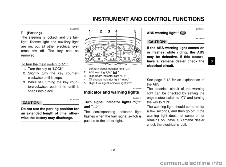
13
45
2
1. Left turn signal indicator light “4”
2. ABS warning light “”
3. High beam indicator light “&”
4. Oil change indicator light “
7”
5. Right turn signal indicator light “6”
5SJ-28199-E1 7/11/02 11:03 AM Page 17
Page 20 of 116

3-3
EWA00069
w
When the ABS warning light
comes on or flashes while riding,
the brake system reverts to con-
ventional braking. Therefore, be
careful not to cause the wheel to
lock during emergency braking.
NOTE:
The ABS warning light may come on
while pushing the start switch and
while accelerating the engine with the
scooter on its centerstand, but this
does not indicate a malfunction.
EAU00063
High beam indicator light “&”High beam indicator lightThis indicator light comes on when
the high beam of the headlight is
switched on.
INSTRUMENT AND CONTROL FUNCTIONS
3
EAU03734
Oil change indicator light “7”Oil change indicator lightThis indicator light comes on at the
initial 1,000 km and every 3,000 km
thereafter to indicate that the engine
oil should be changed.
If the engine oil is changed before the
oil change indicator comes on (i.e.
before the periodic oil change interval
has been reached), the indicator light
must be reset after the oil change for
the next periodic oil change to be
indicated at the correct time. (See
page 6-17 for the resetting proce-
dure.)
The electrical circuit of the indicator
light can be checked according to the
following procedure.
1. Set the engine stop switch to “#”
and turn the key to “ON”.
2. Check that the indicator comes
on for a few seconds and then
goes off.
3. If the indicator light does not
come on, have a Yamaha dealer
check the electrical circuit.
NOTE:
The oil change indicator light may
flash when the engine is revved with
the scooter on the centerstand, but
this does not indicate a malfunction.
5SJ-28199-E1 7/11/02 11:03 AM Page 18
Page 27 of 116

3-10
INSTRUMENT AND CONTROL FUNCTIONS
3
EAU00109
Anti-theft alarm (optional)Anti-theft alarm (optional)This scooter can be equipped with an
optional anti-theft alarm by a Yamaha
dealer. Contact a Yamaha dealer for
more information.
EAU03889
Turn signal switch “4/6”Turn signal switchTo signal a right-hand turn, push this
switch to “6”. To signal a left-hand
turn, push this switch to “4”. When
released, the switch returns to the
center position. To cancel the turn
signal lights, push the switch in after
it has returned to the center position.
EAU00129
Horn switch “*”Horn switchPress this switch to sound the horn.EAU00118
Handlebar switches
Handlebar switchesEAU00120
Pass switch “PASS”Pass switchPress this switch to flash the head-
light.
EAU03888
Dimmer switch “&/%”Dimmer switchSet this switch to “&” for the high
beam and to “%” for the low beam.
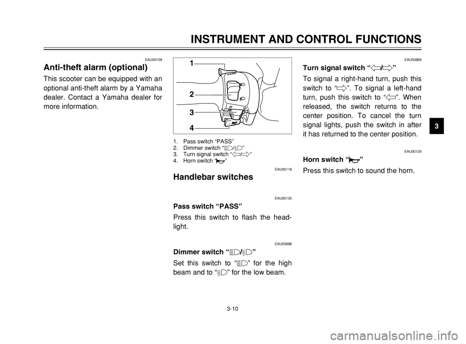
1
2
3
4
1. Pass switch “PASS”
2. Dimmer switch “&/%”
3. Turn signal switch “4/6”
4. Horn switch “*”
5SJ-28199-E1 7/11/02 11:03 AM Page 25
Page 107 of 116

8-4
SPECIFICATIONS
8
Bulb voltage, wattage ×quantity
Headlight 12 V, 60/55 W ×1
12 V, 55 W ×1
Tail/brake light 12 V, 5/21 W ×2
Front turn signal light 12 V, 21 W ×2
Rear turn signal light 12 V, 18 W ×2
Auxiliary light 12 V, 5 W ×1
License plate light 12 V, 5 W ×1
Meter lighting 12 V, 1.7 W ×4
High beam indicator light 12 V, 1.7 W ×1
Turn signal indicator light 12 V, 3.4 W ×2
Oil change indicator light 12 V, 1.7 W ×1
ABS warning light 12 V, 1.7 W ×1
Fuses
Main fuse 30 A
ABS motor fuse 30 A
Headlight fuse 15 A
Signaling system fuse 15 A
ABS control unit fuse 10 A
Ignition fuse 7.5 A
Radiator fan fuse 4 A
Clock (Backup) fuse 10 A
5SJ-28199-E1 7/11/02 11:03 AM Page 105
Page 112 of 116

INDEX
D
Display, multi-function ............................3-5
E
Engine break-in ......................................5-4
Engine oil ..............................................6-14
F
Final transmission oil ............................6-18
Front and rear brake lever free play,
adjusting ...........................................6-27
Front and rear brake pads, checking ....6-28
Front fork, checking ..............................6-32
Fuel ......................................................3-16
Fuel consumption, tips for reducing .......5-4
Fuel gauge .............................................3-5
Fuel tank cap ........................................3-15
Fuses, replacing ...................................6-36
H
Handlebar switches ..............................3-10
Dimmer switch ..................................3-10
Engine stop switch ............................3-11
Horn switch .......................................3-10
Pass switch .......................................3-10
Start switch .......................................3-11
Turn signal switch .............................3-10
Headlight bulb, replacing ......................6-37I
Identification numbers ............................9-1
Ignition circuit cut-off system ................3-22
Indicator and warning lights ....................3-2
ABS warning light ................................3-2
High beam indicator light .....................3-3
Oil change indicator light .....................3-3
Turn signal indicator lights ...................3-2
K
Key identification number .......................9-1
L
License plate light bulb, replacing ........6-41
M
Main switch/steering lock .......................3-1
Model label .............................................9-2
P
Parking ...................................................5-5
Part locations ..........................................2-1
Periodic maintenance and lubrication
chart .....................................................6-3
Pre-operation check list ..........................4-1
R
Rider seat .............................................3-18
Rider seat, adjusting .............................3-18A
ABS ......................................................3-13
Acceleration and deceleration ................5-3
Air filter and V-belt case air filter
elements, cleaning ............................6-21
Air flow louver .......................................6-23
Anti-theft alarm (optional) .....................3-10
B
Battery ..................................................6-34
Battery cover removal ..........................6-34
Brake fluid level, checking ....................6-29
Brake fluid, changing ............................6-30
Brake lever, front ..................................3-11
Brake lever, rear ...................................3-12
Brake levers, lubricating .......................6-31
Braking ...................................................5-3
C
Cables, checking and lubricating ..........6-30
Care ........................................................7-1
Catalytic converter ................................3-17
Centerstand and sidestand, checking
and lubricating ..................................6-31
Conversion table ....................................8-5
Coolant .................................................6-19
Coolant temperature gauge ....................3-5
Cowlings and panel, removing and
installing ..............................................6-6
5SJ-28199-E1 7/11/02 11:03 AM Page 110