YAMAHA MT-03 2006 Owners Manual
Manufacturer: YAMAHA, Model Year: 2006, Model line: MT-03, Model: YAMAHA MT-03 2006Pages: 99, PDF Size: 7.24 MB
Page 91 of 99
1
2
3
4
5
6
7
8
9
10
SPECIFICATIONS
8-2
Operation:
Left foot operation
Gear ratio:
1
st:
30/12 (2.500)
2
nd:
26/16 (1.625)
3
rd:
23/20 (1.150)
4
th:
20/22 (0.909)
5
th:
20/26 (0.769)
Chassis:
Frame type:
Truss diamond
Caster angle:
26°
Trail:
97.0 mm (3.81 in)
Front tire:
Type:
Tubeless
Size:
120/70-ZR17M/C (58W),
120/70-R17M/C (58H)
Manufacturer/model:
DUNLOP D270F
PIRELLI SCORPION SYNC
Rear tire:
Type:
Tubeless
Size:
160/60-ZR17M/C (69W),
160/60-R17M/C (69H)Manufacturer/model:
DUNLOP D270
PIRELLI SCORPION SYNC
Load:
Maximum load:
186 kg (410 lb)
(Total weight of rider, passenger, cargo
and accessories)
Tire air pressure
(measured on cold tires):
Load:
Up to 90 kg (0-198 lb)
Front:
210 kPa (30 psi) (2.1 kgf/cm
3)
Rear:
230 kPa (33 psi) (2.3 kgf/cm
3)
Load:
90-186 kg (198-410 lb)
Front:
230 kPa (33 psi) (2.3 kgf/cm
3)
Rear:
250 kPa (36 psi) (2.5 kgf/cm
3)
High-speed riding:
Front:
210 kPa (30 psi) (2.1 kgf/cm
3)
Rear:
230 kPa (33 psi) (2.3 kgf/cm
3)
Front wheel:
Type:
Cast wheel
Rim size:
17M/C x MT3.50
Rear wheel:
Type:
Cast wheel
Rim size:
17M/C x MT5.00
Front brake:
Type:
Dual disc brake
Operation:
Right hand
Fluid:
DOT 4
Rear brake:
Type:
Single disc brake
Operation:
Right foot
Fluid:
DOT 4
Front suspension:
Type:
Telescopic fork
Spring/damper type:
Coil spring/oil damper
Wheel travel:
130 mm (5.12 in)
Rear suspension:
Type:
Swingarm
Spring/damper type:
Coil spring/gas-oil damper,
spring preload adjustable
Wheel travel:
120.0 mm (4.72 in)
MY03 07-10 ING 5-10-2005 17:09 Pagina 7
Page 92 of 99
SPECIFICATIONS
8-3
1
2
3
4
5
6
7
8
9
10
Electrical system:
Ignition system:
Transistorized coil ignition (digital)
Charging system:
A.C. magneto
Battery:
Model:
GT9B-4
Voltage, capacity:
12 V, 8 Ah
Headlight:
Bulb type:
Halogen bulb
Bulb voltage, wattage x quantity:
Headlight:
12 V, 55 W/60 W x 1
Auxiliary light:
12 V, 3 W x 1
Tail/brake light:
12 V, 5 W/21 W x 1
Front turn signal light:
12 V, 10 W x 2
Rear turn signal light:
12 V, 10 W x 2
Meter lighting:
LED (backlight)
Neutral indicator light:
LED
Turn signal indicator light:
LED
High beam indicator light:
LED
Fuel level warning light:
LEDCoolant temperature warning light:
LED
Engine trouble warning light:
LED
Immobilizer system indicator light:
LED
Fuses:Main fuse:
30 A
Headlight fuse:
20 A
Signaling system fuse:
10 A
Ignition fuse:
10 A
Parking lighting fuse:
10 A
Radiator fan fuse:
7.5 A
Fuel injection system fuse:
10 A
Backup fuse (for odometer, clock and
immobilizer):
10 A
MY03 07-10 ING 5-10-2005 17:09 Pagina 8
Page 93 of 99
1
2
3
4
5
6
7
8
9
10
CONSUMER INFORMATION
9-1
EAU26351
Identification numbers
Record the key identification number,
vehicle identification number and
model label information in the spaces
provided below for assistance when
ordering spare parts from a Yamaha
dealer or for reference in case the ve-
hicle is stolen.
KEY IDENTIFICATION NUMBER:
VEHICLE IDENTIFICATION NUMBER:
MODEL LABEL INFORMATION:
å
ç
EAU26381
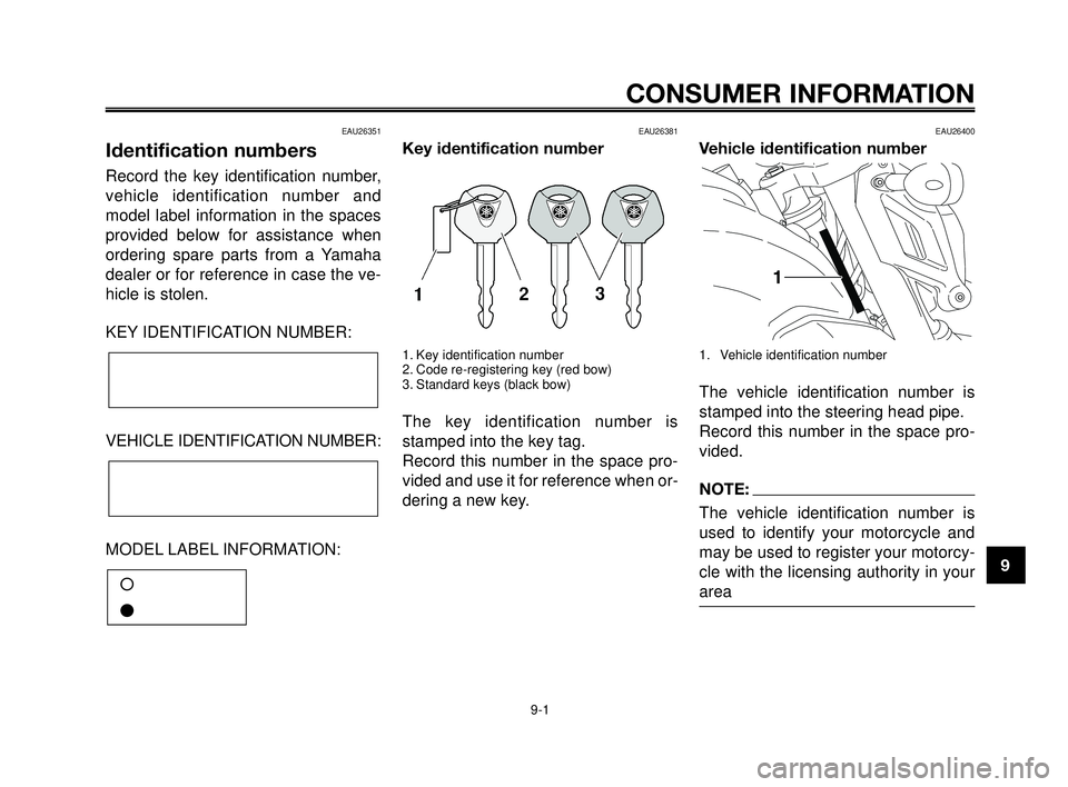
Key identification number
1. Key identification number
2. Code re-registering key (red bow)
3. Standard keys (black bow)
The key identification number is
stamped into the key tag.
Record this number in the space pro-
vided and use it for reference when or-
dering a new key.
EAU26400
Vehicle identification number
1. Vehicle identification number
The vehicle identification number is
stamped into the steering head pipe.
Record this number in the space pro-
vided.
NOTE:
The vehicle identification number is
used to identify your motorcycle and
may be used to register your motorcy-
cle with the licensing authority in your
area
MY03 07-10 ING 5-10-2005 17:09 Pagina 1
Page 94 of 99
CONSUMER INFORMATION
9-2
1
2
3
4
5
6
7
8
9
10
EAU26520
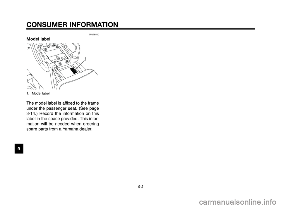
Model label
1. Model label
The model label is affixed to the frame
under the passenger seat. (See page
3-14.) Record the information on this
label in the space provided. This infor-
mation will be needed when ordering
spare parts from a Yamaha dealer.
MY03 07-10 ING 5-10-2005 17:09 Pagina 2
Page 95 of 99
1
2
3
4
5
6
7
8
9
10
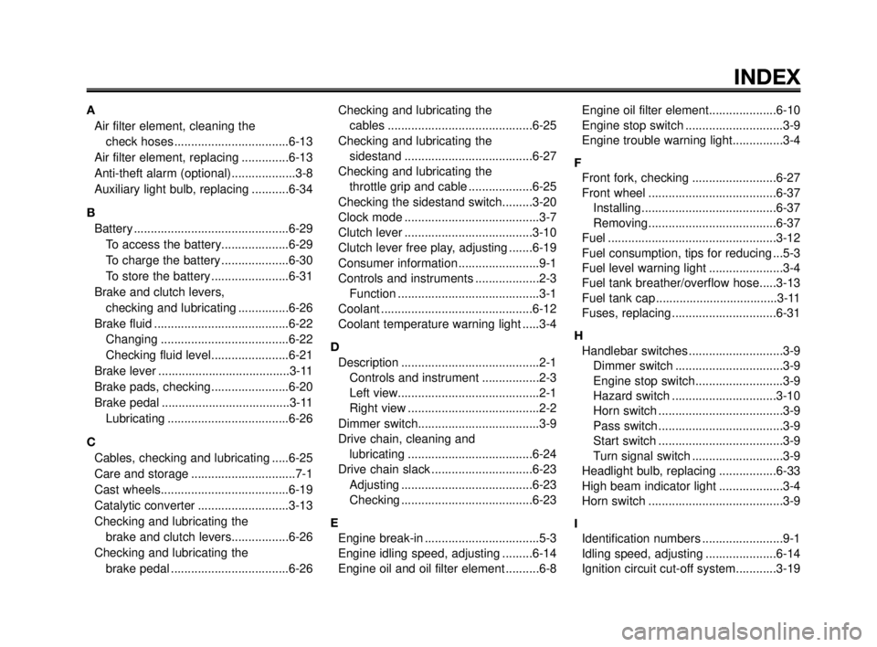
INDEX
A
Air filter element, cleaning the
check hoses ..................................6-13
Air filter element, replacing ..............6-13
Anti-theft alarm (optional)...................3-8
Auxiliary light bulb, replacing ...........6-34
B
Battery ..............................................6-29
To access the battery....................6-29
To charge the battery ....................6-30
To store the battery .......................6-31
Brake and clutch levers,
checking and lubricating ...............6-26
Brake fluid ........................................6-22
Changing ......................................6-22
Checking fluid level.......................6-21
Brake lever .......................................3-11
Brake pads, checking.......................6-20
Brake pedal ......................................3-11
Lubricating ....................................6-26
C
Cables, checking and lubricating .....6-25
Care and storage ...............................7-1
Cast wheels......................................6-19
Catalytic converter ...........................3-13
Checking and lubricating the
brake and clutch levers.................6-26
Checking and lubricating the
brake pedal ...................................6-26Checking and lubricating the
cables ...........................................6-25
Checking and lubricating the
sidestand ......................................6-27
Checking and lubricating the
throttle grip and cable ...................6-25
Checking the sidestand switch.........3-20
Clock mode ........................................3-7
Clutch lever ......................................3-10
Clutch lever free play, adjusting .......6-19
Consumer information ........................9-1
Controls and instruments ...................2-3
Function ..........................................3-1
Coolant .............................................6-12
Coolant temperature warning light .....3-4
D
Description .........................................2-1
Controls and instrument .................2-3
Left view..........................................2-1
Right view .......................................2-2
Dimmer switch....................................3-9
Drive chain, cleaning and
lubricating .....................................6-24
Drive chain slack ..............................6-23
Adjusting .......................................6-23
Checking .......................................6-23
E
Engine break-in ..................................5-3
Engine idling speed, adjusting .........6-14
Engine oil and oil filter element ..........6-8Engine oil filter element....................6-10
Engine stop switch .............................3-9
Engine trouble warning light...............3-4
F
Front fork, checking .........................6-27
Front wheel ......................................6-37
Installing........................................6-37
Removing......................................6-37
Fuel ..................................................3-12
Fuel consumption, tips for reducing ...5-3
Fuel level warning light ......................3-4
Fuel tank breather/overflow hose.....3-13
Fuel tank cap ....................................3-11
Fuses, replacing ...............................6-31
H
Handlebar switches ............................3-9
Dimmer switch ................................3-9
Engine stop switch..........................3-9
Hazard switch ...............................3-10
Horn switch .....................................3-9
Pass switch .....................................3-9
Start switch .....................................3-9
Turn signal switch ...........................3-9
Headlight bulb, replacing .................6-33
High beam indicator light ...................3-4
Horn switch ........................................3-9
I
Identification numbers ........................9-1
Idling speed, adjusting .....................6-14
Ignition circuit cut-off system............3-19
MY03 07-10 ING 5-10-2005 17:09 Pagina 1
Page 96 of 99
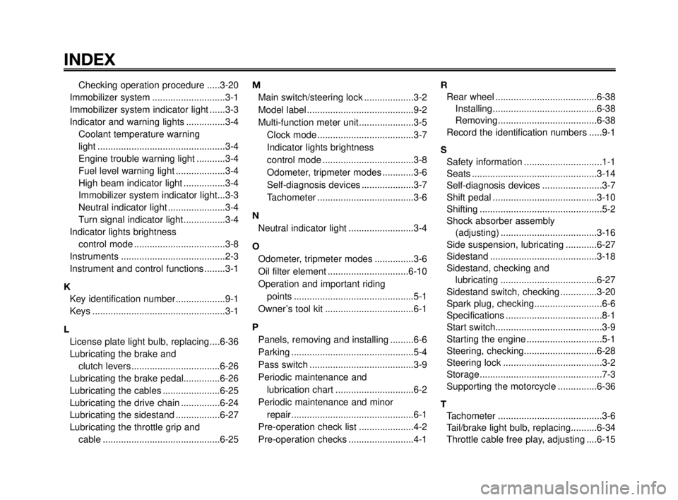
INDEX
1
2
3
4
5
6
7
8
9
10
Checking operation procedure .....3-20
Immobilizer system ............................3-1
Immobilizer system indicator light ......3-3
Indicator and warning lights ...............3-4
Coolant temperature warning
light .................................................3-4
Engine trouble warning light ...........3-4
Fuel level warning light ...................3-4
High beam indicator light ................3-4
Immobilizer system indicator light...3-3
Neutral indicator light ......................3-4
Turn signal indicator light................3-4
Indicator lights brightness
control mode ...................................3-8
Instruments ........................................2-3
Instrument and control functions ........3-1
K
Key identification number...................9-1
Keys ...................................................3-1
L
License plate light bulb, replacing....6-36
Lubricating the brake and
clutch levers ..................................6-26
Lubricating the brake pedal..............6-26
Lubricating the cables ......................6-25
Lubricating the drive chain ...............6-24
Lubricating the sidestand .................6-27
Lubricating the throttle grip and
cable .............................................6-25M
Main switch/steering lock ...................3-2
Model label .........................................9-2
Multi-function meter unit.....................3-5
Clock mode .....................................3-7
Indicator lights brightness
control mode ...................................3-8
Odometer, tripmeter modes ............3-6
Self-diagnosis devices ....................3-7
Tachometer .....................................3-6
N
Neutral indicator light .........................3-4
O
Odometer, tripmeter modes ...............3-6
Oil filter element ...............................6-10
Operation and important riding
points ..............................................5-1
Owner’s tool kit ..................................6-1
P
Panels, removing and installing .........6-6
Parking ...............................................5-4
Pass switch ........................................3-9
Periodic maintenance and
lubrication chart ..............................6-2
Periodic maintenance and minor
repair...............................................6-1
Pre-operation check list .....................4-2
Pre-operation checks .........................4-1R
Rear wheel .......................................6-38
Installing........................................6-38
Removing......................................6-38
Record the identification numbers .....9-1
S
Safety information ..............................1-1
Seats ................................................3-14
Self-diagnosis devices .......................3-7
Shift pedal ........................................3-10
Shifting ...............................................5-2
Shock absorber assembly
(adjusting) .....................................3-16
Side suspension, lubricating ............6-27
Sidestand .........................................3-18
Sidestand, checking and
lubricating .....................................6-27
Sidestand switch, checking ..............3-20
Spark plug, checking..........................6-6
Specifications .....................................8-1
Start switch.........................................3-9
Starting the engine .............................5-1
Steering, checking............................6-28
Steering lock ......................................3-2
Storage...............................................7-3
Supporting the motorcycle ...............6-36
T
Tachometer ........................................3-6
Tail/brake light bulb, replacing..........6-34
Throttle cable free play, adjusting ....6-15
MY03 07-10 ING 5-10-2005 17:09 Pagina 2
Page 97 of 99
1
2
3
4
5
6
7
8
9
10
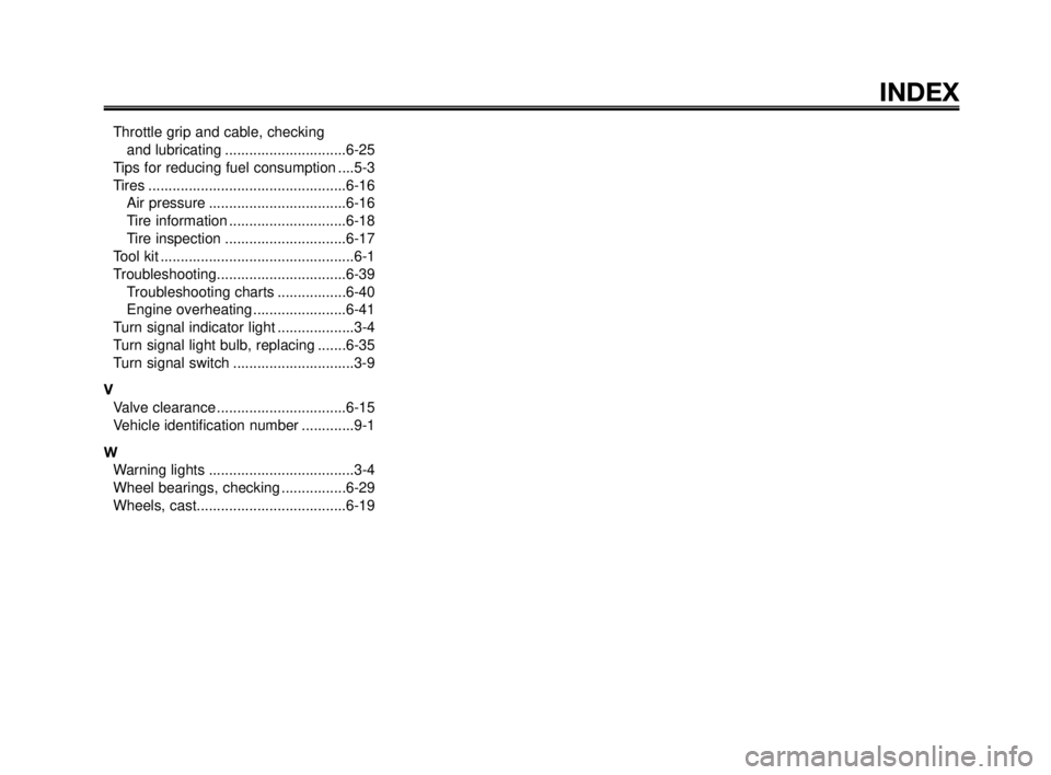
INDEX
Throttle grip and cable, checking
and lubricating ..............................6-25
Tips for reducing fuel consumption ....5-3
Tires .................................................6-16
Air pressure ..................................6-16
Tire information .............................6-18
Tire inspection ..............................6-17
Tool kit ................................................6-1
Troubleshooting................................6-39
Troubleshooting charts .................6-40
Engine overheating .......................6-41
Turn signal indicator light ...................3-4
Turn signal light bulb, replacing .......6-35
Turn signal switch ..............................3-9
V
Valve clearance ................................6-15
Vehicle identification number .............9-1
W
Warning lights ....................................3-4
Wheel bearings, checking ................6-29
Wheels, cast.....................................6-19
MY03 07-10 ING 5-10-2005 17:09 Pagina 3
Page 98 of 99

1
2
3
4
5
6
7
8
9
10
MY03 07-10 ING 5-10-2005 17:09 Pagina 4
Page 99 of 99

PRINTED IN ITALY
YAMAHA MOTOR ITALIA S.P.A.
Quarta cop. GB colori 6-10-2005 11:21 Pagina 2