engine coolant YAMAHA MT-07 2014 User Guide
[x] Cancel search | Manufacturer: YAMAHA, Model Year: 2014, Model line: MT-07, Model: YAMAHA MT-07 2014Pages: 106, PDF Size: 3.29 MB
Page 62 of 106

PERIODIC MAINTENANCE AND ADJUSTMENT
6-13
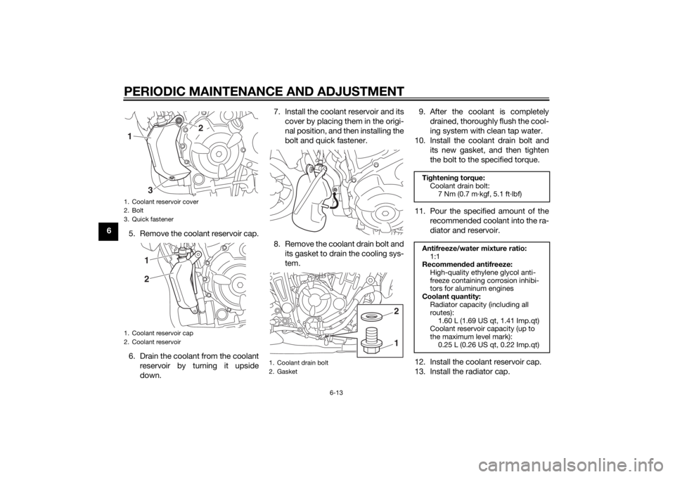
65. Remove the coolant reservoir cap.
6. Drain the coolant from the coolant
reservoir by turning it upside
down. 7. Install the coolant reservoir and its
cover by placing them in the origi-
nal position, and then installing the
bolt and quick fastener.
8. Remove the coolant drain bolt and its gasket to drain the cooling sys-
tem. 9. After the coolant is completely
drained, thoroughly flush the cool-
ing system with clean tap water.
10. Install the coolant drain bolt and its new gasket, and then tighten
the bolt to the specified torque.
11. Pour the specified amount of the recommended coolant into the ra-
diator and reservoir.
12. Install the coolant reservoir cap.
13. Install the radiator cap.
1. Coolant reservoir cover
2. Bolt
3. Quick fastener
1. Coolant reservoir cap
2. Coolant reservoir
2
1
321
1. Coolant drain bolt
2. Gasket
12
Ti ghtenin g torque:
Coolant drain bolt: 7 Nm (0.7 m·kgf, 5.1 ft·lbf)
Antifreeze/water mixture ratio: 1:1
Recommen ded antifreeze:
High-quality ethylene glycol anti-
freeze containing corrosion inhibi-
tors for aluminum engines
Coolant quantity: Radiator capacity (including all
routes):
1.60 L (1.69 US qt, 1.41 Imp.qt)
Coolant reservoir capacity (up to
the maximum level mark):
0.25 L (0.26 US qt, 0.22 Imp.qt)
U1WSE0E0.book Page 13 Wednesday, November 13, 2013 10:28 AM
Page 63 of 106

PERIODIC MAINTENANCE AND ADJUSTMENT
6-14
6
14. Start the engine, let it idle for sev-
eral minutes, and then turn it off.
15. Remove the radiator cap to check the coolant level in the radiator. If
necessary, add sufficient coolant
until it reaches the top of the radi-
ator, and then install the radiator
cap and radiator cap retaining
bolt.
16. Check the coolant level in the res- ervoir. If necessary, remove the
coolant reservoir cap, add coolant
to the maximum level mark, and
then install the cap.
17. Start the engine, and then check the vehicle for coolant leakage. If
coolant is leaking, have a Yamaha
dealer check the cooling system.
EAU60450
Replacin g the air filter ele-
ment an d cleanin g the check
hoseThe air filter element should be re-
placed at the intervals specified in the
periodic maintenance and lubrication
chart. Have a Yamaha dealer replace
the air filter element more frequently if
you are riding in unusually wet or dusty
areas. However, the air filter check
hose can be easily reached and should
be frequently checked and cleaned if
necessary.
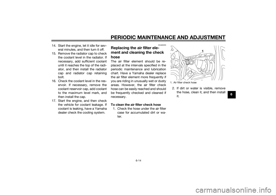
To clean the air filter check hose
1. Check the hose under the air filter case for accumulated dirt or wa-
ter. 2. If dirt or water is visible, remove
the hose, clean it, and then install
it.
1. Air filter check hose
1
U1WSE0E0.book Page 14 Wednesday, November 13, 2013 10:28 AM
Page 92 of 106

PERIODIC MAINTENANCE AND ADJUSTMENT
6-43
6En
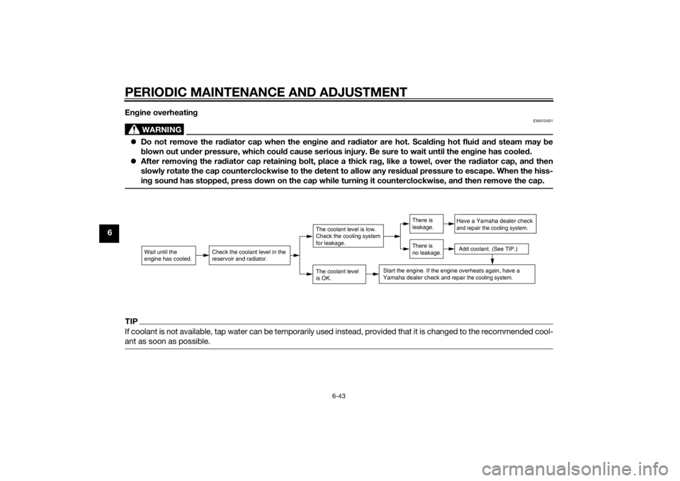
gine overheatin g
WARNING
EWA10401
Do not remove the ra diator cap when the en gine an d ra diator are hot. Scal din g hot flui d an d steam may be
b lown out un der pressure, which coul d cause serious injury. Be sure to wait until the en gine has coole d.
After removin g the ra diator cap retainin g b olt, place a thick ra g, like a towel, over the rad iator cap, and then
slowly rotate the cap counterclockwise to the d etent to allow any residual pressure to escape. When the hiss-
in g soun d has stoppe d, press d own on the cap while turnin g it counterclockwise, an d then remove the cap.TIPIf coolant is not available, tap water can be temporarily used instead, provided that it is changed to the recommended cool-
ant as soon as possible.
Wait until the
engine has cooled.
Check the coolant level in the
reservoir and radiator.
The coolant level
is OK.The coolant level is low.
Check the cooling system
for leakage.
Have a Yamaha dealer checkand repair the cooling system.Add coolant. (See TIP.)
Start the engine. If the engine overheats again,
have a
Yamaha dealer check
and repair the cooling system.
There is
leakage.
There is
no leakage.
U1WSE0E0.book Page 43 Wednesday, November 13, 2013 10:28 AM
Page 97 of 106

SPECIFICATIONS
8-1
8
Dimensions:Overall length:2085 mm (82.1 in)
Overall width:
745 mm (29.3 in)
Overall height: 1090 mm (42.9 in)
Seat height: 805 mm (31.7 in)
Wheelbase:
1400 mm (55.1 in)
Ground clearance: 140 mm (5.51 in)
Minimum turning radius: 2694 mm (106.1 in)Wei ght:Curb weight:
MT07 179 kg (395 lb)
MT07A 182 kg (401 lb)Engine:Engine type:
Liquid cooled 4-stroke, DOHC
Cylinder arrangement:
Inline 2-cylinder
Displacement: 689 cm³
Bore × stroke:
80.0 × 68.6 mm (3.15 × 2.70 in)
Compression ratio:
11.50 : 1
Starting system: Electric starter
Lubrication system: Wet sump
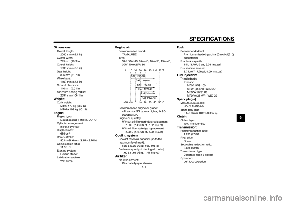
Engine oil:Recommended brand:
YAMALUBE
Type:
SAE 10W-30, 10W-40, 10W-50, 15W-40,
20W-40 or 20W-50
Recommended engine oil grade: API service SG type or higher, JASO
standard MA
Engine oil quantity:
Without oil filter cartridge replacement:2.30 L (2.43 US qt, 2.02 Imp.qt)
With oil filter cartridge replacement:
2.60 L (2.75 US qt, 2.29 Imp.qt)Coolin g system:Coolant reservoir capacity (up to the
maximum level mark):
0.25 L (0.26 US qt, 0.22 Imp.qt)
Radiator capacity (including all routes): 1.60 L (1.69 US qt, 1.41 Imp.qt)Air filter:Air filter element:Oil-coated paper element
Fuel:Recommended fuel:Premium unleaded gasoline (Gasohol (E10)
acceptable)
Fuel tank capacity: 14 L (3.70 US gal, 3.08 Imp.gal)
Fuel reserve amount:
2.7 L (0.71 US gal, 0.59 Imp.gal)Fuel injection:Throttle body:ID mark:MT07 1WS1 00
MT07 (35 kW) 1WS2 20
MT07A 1WS1 00
MT07A (35 kW) 1WS2 20Spark plu g(s):Manufacturer/model:
NGK/LMAR8A-9
Spark plug gap: 0.8–0.9 mm (0.031–0.035 in)Clutch:Clutch type:
Wet, multiple-discTransmission:Primary reduction ratio:1.925 (77/40)
Final drive:
Chain
Secondary reduction ratio: 2.688 (43/16)
Transmission type: Constant mesh 6-speed
Operation:
Left foot operation
–20 –10 0 1020 30 40 50 �C
10 30 50 70 90 110
0 130 �F
SAE 10W-30
SAE 15W-40SAE 20W-40SAE 20W-50
SAE 10W-40SAE 10W-50
U1WSE0E0.book Page 1 Wednesday, November 13, 2013 10:28 AM
Page 99 of 106

SPECIFICATIONS
8-3
8
Battery:Model:YTZ10S
Voltage, capacity:
12 V, 8.6 AhHea dlig ht:Bulb type:
Halogen bulbBul b volta ge, watta ge × quantity:Headlight:
12 V, 60.0 W/55.0 W × 1
Tail/brake light: LED
Front turn signal light:
12 V, 10.0 W × 2
Rear turn signal light: 12 V, 10.0 W × 2
Auxiliary light: 12 V, 5.0 W × 1
License plate light:
12 V, 5.0 W × 1
Meter lighting: LED
Neutral indicator light: LED
High beam indicator light:
LED
Oil pressure warning light: LED
Turn signal indicator light: LED
Coolant temperature warning light:
LED Engine trouble warning light:
LED
ABS warning light: MT07A LED
Immobilizer system indicator light:
LED
Fuses:Main fuse:30.0 A
Auxiliary fuse:
2.0 A
Headlight fuse: 15.0 A
Signaling system fuse: 10.0 A
Ignition fuse:
10.0 A
Parking lighting fuse: 7.5 A
Radiator fan fuse: 10.0 A
Fuel injection system fuse:
10.0 A
ABS control unit fuse: MT07A 7.5 A
ABS motor fuse: MT07A 30.0 A
ABS solenoid fuse:
MT07A 20.0 A
Backup fuse: 7.5 A
U1WSE0E0.book Page 3 Wednesday, November 13, 2013 10:28 AM
Page 102 of 106

10-1
10
INDEXAABS (for ABS models) ........................... 3-15
ABS warning light (for ABS models) ....... 3-5
Air filter element and check hose, replacing and cleaning ....................... 6-14
Auxiliary DC connector ......................... 3-27
Auxiliary light bulb, replacing ................ 6-36BBattery .................................................. 6-29
Brake and clutch levers, checking and lubricating .................... 6-26
Brake and shift pedals,
checking and lubricating .................... 6-25
Brake fluid, changing ............................ 6-22
Brake fluid level, checking .................... 6-21
Brake lever ............................................ 3-14
Brake lever free play, checking............. 6-19
Brake light switches.............................. 6-19
Brake pedal........................................... 3-15CCables, checking and lubricating ......... 6-25
Care ........................................................ 7-1
Catalytic converter ................................ 3-19
Clutch lever ........................................... 3-14
Clutch lever free play, adjusting ........... 6-18
Coolant ................................................. 6-11
Coolant temperature warning light ......... 3-4DDimmer switch ...................................... 3-13
Drive chain, cleaning and lubricating .... 6-24
Drive chain slack................................... 6-22EEngine break-in....................................... 5-3
Engine oil and oil filter cartridge ............. 6-9 Engine serial number .............................. 9-1
Engine trouble warning light ................... 3-4
FFront and rear brake pads, checking ... 6-20
Front fork, checking ............................. 6-28
Fuel ....................................................... 3-17
Fuel consumption, tips for reducing ...... 5-3
Fuel tank breather hose and overflow
hose ................................................... 3-18
Fuel tank cap ........................................ 3-16
Fuses, replacing ................................... 6-31HHandlebar switches .............................. 3-13
Hazard switch....................................... 3-13
Headlight bulb, replacing ..................... 6-32
Helmet holding cable ........................... 3-21
High beam indicator light ....................... 3-4
Horn switch .......................................... 3-13IIdentification numbers ............................ 9-1
Ignition circuit cut-off system ............... 3-25
Immobilizer system ................................ 3-1
Immobilizer system indicator light .......... 3-5
Indicator lights and warning lights ......... 3-3LLicense plate light bulb, replacing........ 6-35
Luggage strap holders ......................... 3-24MMain switch/steering lock....................... 3-2
Maintenance and lubrication, periodic ... 6-4
Maintenance, emission control system.................................................. 6-3
Matte color, caution ............................... 7-1
Model label ............................................. 9-1 Multi-function meter unit .........................3-6
NNeutral indicator light ..............................3-4OOil pressure warning light .......................3-4PParking ....................................................5-4
Part locations ..........................................2-1
Pass switch ...........................................3-13RRear suspension, lubricating ................6-27SSafety information ...................................1-1
Seats .....................................................3-19
Shifting ....................................................5-2
Shift pedal .............................................3-14
Shock absorber assembly, adjusting ....3-23
Sidestand ..............................................3-24
Sidestand, checking and lubricating.....6-27
Spark plugs, checking ............................6-8
Specifications .........................................8-1
Start/Engine stop switch .......................3-13
Starting the engine ..................................5-1
Steering, checking ................................6-28
Storage ...................................................7-3
Storage compartment ...........................3-22
Supporting the motorcycle ...................6-36
Swingarm pivots, lubricating ................6-27TTail/brake light ......................................6-34
Throttle grip and cable,
checking and lubricating ....................6-25
Throttle grip free play, checking ...........6-15
Tires ......................................................6-15
U1WSE0E0.book Page 1 Wednesday, November 13, 2013 10:28 AM