ignition YAMAHA MT-07 2014 Owners Manual
[x] Cancel search | Manufacturer: YAMAHA, Model Year: 2014, Model line: MT-07, Model: YAMAHA MT-07 2014Pages: 106, PDF Size: 3.29 MB
Page 6 of 106

TABLE OF CONTENTSSAFETY INFORMATION.................. 1-1
DESCRIPTION .................................. 2-1
Left view ......................................... 2-1
Right view ....................................... 2-2
Controls and instruments ............... 2-3
INSTRUMENT AND CONTROL
FUNCTIONS ...................................... 3-1
Immobilizer system......................... 3-1
Main switch/steering lock............... 3-2
Indicator lights and warning lights............................................ 3-3
Multi-function meter unit ................ 3-6
Handlebar switches ...................... 3-13
Clutch lever .................................. 3-14
Shift pedal .................................... 3-14
Brake lever.................................... 3-14
Brake pedal .................................. 3-15
ABS (for ABS models) .................. 3-15
Fuel tank cap ................................ 3-16
Fuel ............................................... 3-17
Fuel tank breather hose and
overflow hose ............................ 3-18
Catalytic converter ....................... 3-19
Seats ............................................ 3-19
Helmet holding cable.................... 3-21
Storage compartment .................. 3-22
Adjusting the shock absorber assembly ................................... 3-23
Luggage strap holders ................. 3-24 Sidestand ...................................... 3-24
Ignition circuit cut-off system ....... 3-25
Auxiliary DC connector ................. 3-27
FOR YOUR SAFETY –
PRE-OPERATION CHECKS ............. 4-1
OPERATION AND IMPORTANT
RIDING POINTS ................................ 5-1
Starting the engine .......................... 5-1
Shifting ............................................ 5-2
Tips for reducing fuel consumption ................................ 5-3
Engine break-in ............................... 5-3
Parking ............................................ 5-4
PERIODIC MAINTENANCE AND
ADJUSTMENT ................................... 6-1
Owner’s tool kit ............................... 6-2
Periodic maintenance chart for the emission control system .............. 6-3
General maintenance and lubrication chart ........................... 6-4
Checking the spark plugs ............... 6-8
Engine oil and oil filter cartridge...... 6-9
Coolant.......................................... 6-11
Replacing the air filter element and cleaning the check hose..... 6-14
Checking the throttle grip free
play ............................................ 6-15
Valve clearance ............................. 6-15 Tires .............................................. 6-15
Cast wheels .................................. 6-18
Adjusting the clutch lever free
play ............................................ 6-18
Checking the brake lever free
play ............................................ 6-19
Brake light switches ..................... 6-19
Checking the front and rear brake pads .......................................... 6-20
Checking the brake fluid level ...... 6-21
Changing the brake fluid .............. 6-22
Drive chain slack........................... 6-22
Cleaning and lubricating the drive chain.......................................... 6-24
Checking and lubricating the cables ........................................ 6-25
Checking and lubricating the
throttle grip and cable ............... 6-25
Checking and lubricating the brake and shift pedals............... 6-25
Checking and lubricating the brake and clutch levers ............. 6-26
Checking and lubricating the
sidestand................................... 6-27
Lubricating the rear suspension ... 6-27
Lubricating the swingarm pivots......................................... 6-27
Checking the front fork ................. 6-28
Checking the steering................... 6-28
Checking the wheel bearings ....... 6-29
Battery .......................................... 6-29U1WSE0E0.book Page 1 Wednesday, November 13, 2013 10:28 AM
Page 17 of 106
INSTRUMENT AND CONTROL FUNCTIONS
3-2
3
Keep other immo bilizer system
keys away from the main switch
as they may cause si gnal inter-
ference.
EAU10473
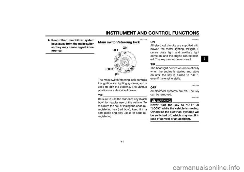
Main switch/steerin g lockThe main switch/steering lock controls
the ignition and lighting systems, and is
used to lock the steering. The various
positions are described below.TIPBe sure to use the standard key (black
bow) for regular use of the vehicle. To
minimize the risk of losing the code re-
registering key (red bow), keep it in a
safe place and only use it for code re-
registering.
EAU38531
ON
All electrical circuits are supplied with
power; the meter lighting, taillight, li-
cense plate light and auxiliary light
come on, and the engine can be start-
ed. The key cannot be removed.TIPThe headlight comes on automatically
when the engine is started and stays
on until the key is turned to “OFF”,
even if the engine stalls.
EAU10662
OFF
All electrical systems are off. The key
can be removed.
WARNING
EWA10062
Never turn the key to “OFF” or
“LOCK” while the vehicle is movin g.
Otherwise the electrical systems will
b e switche d off, which may result in
loss of control or an acci dent.
P
ON
OFF
LOCK
U1WSE0E0.book Page 2 Wednesday, November 13, 2013 10:28 AM
Page 32 of 106
INSTRUMENT AND CONTROL FUNCTIONS
3-17
3
TIPThe fuel tank cap cannot be closed un-
less the key is in the lock. In addition,
the key cannot be removed if the cap is
not properly closed and locked.
WARNING
EWA11092
Make sure that the fuel tank cap is
properly closed after fillin g fuel.
Leakin g fuel is a fire hazar d.
EAU13222
FuelMake sure there is sufficient gasoline in
the tank.
WARNING
EWA10882
Gasoline an d g asoline vapors are
extremely flamma ble. To avoi d fires
an d explosions an d to re duce the
risk of injury when refuelin g, follow
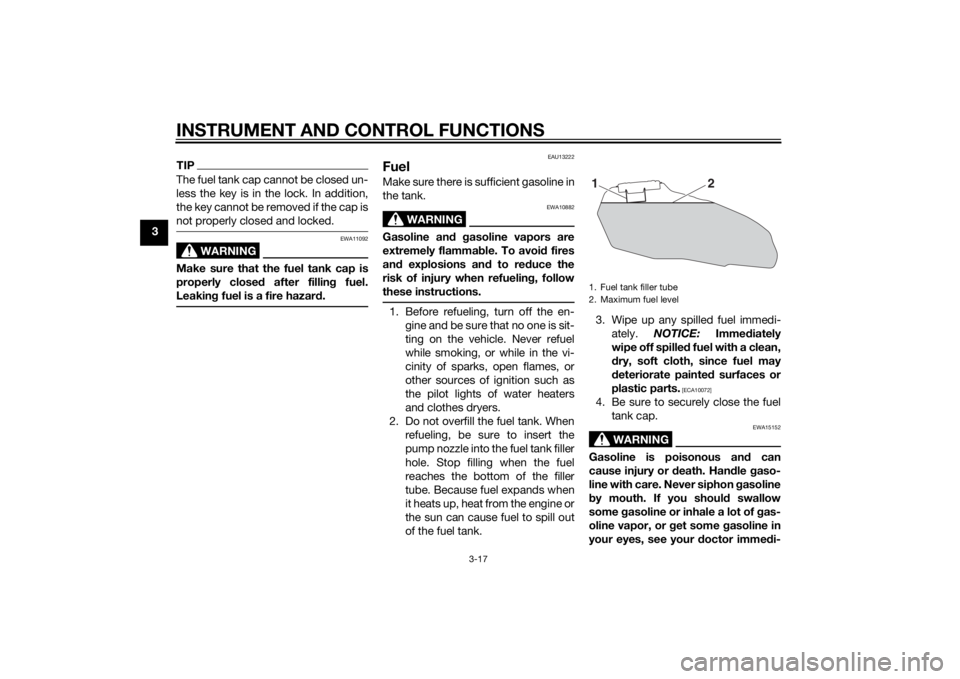
these instructions.1. Before refueling, turn off the en- gine and be sure that no one is sit-
ting on the vehicle. Never refuel
while smoking, or while in the vi-
cinity of sparks, open flames, or
other sources of ignition such as
the pilot lights of water heaters
and clothes dryers.
2. Do not overfill the fuel tank. When refueling, be sure to insert the
pump nozzle into the fuel tank filler
hole. Stop filling when the fuel
reaches the bottom of the filler
tube. Because fuel expands when
it heats up, heat from the engine or
the sun can cause fuel to spill out
of the fuel tank. 3. Wipe up any spilled fuel immedi-
ately. NOTICE: Immediately
wipe off spille d fuel with a clean,
d ry, soft cloth, since fuel may
d eteriorate painted surfaces or
plastic parts.
[ECA10072]
4. Be sure to securely close the fuel tank cap.
WARNING
EWA15152
Gasoline is poisonous an d can
cause injury or death. Han dle gaso-
line with care. Never siphon gasoline
b y mouth. If you shoul d swallow
some gasoline or inhale a lot of g as-
oline vapor, or g et some gasoline in
your eyes, see your doctor imme di-1. Fuel tank filler tube
2. Maximum fuel level
2
1
U1WSE0E0.book Page 17 Wednesday, November 13, 2013 10:28 AM
Page 39 of 106

INSTRUMENT AND CONTROL FUNCTIONS
3-24
3
EAU38963
Lugga ge strap hol dersThere are six luggage strap holders,
four on the bottom of the passenger
seat and one on each passenger foot-
rest. To use the luggage strap holders on the passenger seat, remove the
passenger seat. (See page 3-19.) Un-
hook the straps from the hooks, and
then install the seat with the straps
hanging out from under the passenger
seat.
EAU15306
Si
destan dThe sidestand is located on the left
side of the frame. Raise the sidestand
or lower it with your foot while holding
the vehicle upright.TIPThe built-in sidestand switch is part of
the ignition circuit cut-off system,
which cuts the ignition in certain situa-
tions. (See the following section for an
explanation of the ignition circuit cut-
off system.)
WARNING
EWA10242
The vehicle must not be ri dden with
the si destan d d own, or if the si de-
stan d cannot b e properly move d up
(or does not stay up), otherwise the
si destan d coul d contact the groun d
an d d istract the operator, resultin g
in a possib le loss of control.
Yamaha’s ig nition circuit cut-off
system has been desi gne d to assist
the operator in fulfillin g the respon-
si bility of raisin g the sid estand b e-
fore startin g off. Therefore, check
1. Luggage strap holder
2. Hook
1. Luggage strap holder
12
2
11
U1WSE0E0.book Page 24 Wednesday, November 13, 2013 10:28 AM
Page 40 of 106

INSTRUMENT AND CONTROL FUNCTIONS
3-25
3this system reg
ularly and have a
Yamaha dealer repair it if it does not
function properly.
EAU57950
I g nition circuit cut-off systemThe ignition circuit cut-off system
(comprising the sidestand switch,
clutch switch and neutral switch) has
the following functions.
It prevents starting when the
transmission is in gear and the
sidestand is up, but the clutch le-
ver is not pulled.
It prevents starting when the
transmission is in gear and the
clutch lever is pulled, but the side-
stand is still down.
It cuts the running engine when
the transmission is in gear and the
sidestand is moved down.
Periodically check the operation of the
ignition circuit cut-off system accord-
ing to the following procedure.
U1WSE0E0.book Page 25 Wednesday, November 13, 2013 10:28 AM
Page 45 of 106

FOR YOUR SAFETY – PRE-OPERATION CHECKS
4-3
4
Chassis fasteners• Make sure that all nuts, bolts and screws are properly tightened.
• Tighten if necessary. —
Instruments, li ghts, si gnals
an d switches • Check operation.
• Correct if necessary.
—
Si destan d switch • Check operation of ignition circuit cut-off system.
• If system is not working correctly, have Yamaha dealer check vehicle. 3-24
ITEM CHECKS PAGE
U1WSE0E0.book Page 3 Wednesday, November 13, 2013 10:28 AM
Page 46 of 106
OPERATION AND IMPORTANT RIDING POINTS
5-1
5
EAU15952
Read the Owner’s Manual carefully to
become familiar with all controls. If
there is a control or function you do not
understand, ask your Yamaha dealer.
WARNING
EWA10272
Failure to familiarize yourself with
the controls can lead to loss of con-
trol, which coul d cause an acci dent
or injury.
EAU48711
TIPThis model is equipped with: a lean angle sensor to stop the en-
gine in case of a turnover. In this
case, the multi-function display in-
dicates error code 30, but this is
not a malfunction. Turn the key to
“OFF” and then to “ON” to clear
the error code. Failing to do so will
prevent the engine from starting
even though the engine will crank
when pushing the start switch.
an engine auto-stop system. The
engine stops automatically if left
idling for 20 minutes. If the engine
stops, simply push the start
switch to restart the engine.
EAU59851
Startin g the en gineIn order for the ignition circuit cut-off
system to enable starting, one of the
following conditions must be met:
The transmission is in the neutral
position.
The transmission is in gear with
the clutch lever pulled and the
sidestand up.
See page 3-25 for more informa-
tion.
1. Turn the key to “ON” and make sure that the start/engine stop
switch is set to “ ”.
The following warning lights and
indicator light should come on for
a few seconds, then go off. Coolant temperature warning
light
Engine trouble warning light
Immobilizer system indicator
light
Oil pressure warning light
(This warning light comes on
again after going off briefly,
and then remains on until the
engine is started.)
U1WSE0E0.book Page 1 Wednesday, November 13, 2013 10:28 AM
Page 80 of 106
PERIODIC MAINTENANCE AND ADJUSTMENT
6-31
6
EAU59870
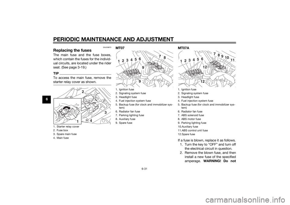
Replacing the fusesThe main fuse and the fuse boxes,
which contain the fuses for the individ-
ual circuits, are located under the rider
seat. (See page 3-19.)TIPTo access the main fuse, remove the
starter relay cover as shown.
MT07 MT07A
If a fuse is blown, replace it as follows. 1. Turn the key to “OFF” and turn off the electrical circuit in question.
2. Remove the blown fuse, and then install a new fuse of the specified
amperage. WARNING! Do not
1. Starter relay cover
2. Fuse box
3. Spare main fuse
4. Main fuse
2
3
4
1
1. Ignition fuse
2. Signaling system fuse
3. Headlight fuse
4. Fuel injection system fuse
5. Backup fuse (for clock and immobilizer sys-
tem)
6. Radiator fan fuse
7. Parking lighting fuse
8. Auxiliary fuse
9. Spare fuse
7
8
1
2
3
4
5
699
1. Ignition fuse
2. Signaling system fuse
3. Headlight fuse
4. Fuel injection system fuse
5. Backup fuse (for clock and immobilizer sys- tem)
6. Radiator fan fuse
7. ABS solenoid fuse
8. ABS motor fuse
9. Parking lighting fuse
10.Auxiliary fuse
11.ABS control unit fuse
12.Spare fuse
7
8
9
10
11
1
2
3
4
5
61212
U1WSE0E0.book Page 31 Wednesday, November 13, 2013 10:28 AM
Page 81 of 106
PERIODIC MAINTENANCE AND ADJUSTMENT
6-32
6
use a fuse of a hi
gher ampera ge
ratin g than recommen ded to
avoi d causin g extensive dam-
a g e to the electrical system an d
possi bly a fire.
[EWA15132]
3. Turn the key to “ON” and turn on
the electrical circuit in question to
check if the device operates.
4. If the fuse immediately blows again, have a Yamaha dealer
check the electrical system.
EAU59881
Replacin g the hea dlig ht bul bThis model is equipped with a halogen
bulb headlight. If the headlight bulb
burns out, replace it as follows.NOTICE
ECA10651
Take care not to d amage the follow-
in g parts:
Hea dlig ht bul b
Do not touch the glass part of
the hea dlig ht bul b to keep it free
from oil, otherwise the transpar-
ency of the glass, the luminosity
of the bul b, an d the bul b life will
b e a dversely affected . Thor-
ou ghly clean off any dirt an d fin-
g erprints on the head lig ht bul b
usin g a cloth moistene d with al-
cohol or thinner.
Hea dlig ht lens
Do not affix any type of tinted
film or stickers to the hea dlig ht
lens.
Do not use a hea dlig ht bul b of a
watta ge hi gher than specified .
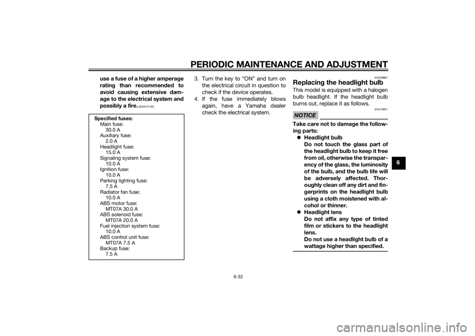
Specified fuses:
Main fuse: 30.0 A
Auxiliary fuse:
2.0 A
Headlight fuse: 15.0 A
Signaling system fuse: 10.0 A
Ignition fuse:
10.0 A
Parking lighting fuse: 7.5 A
Radiator fan fuse: 10.0 A
ABS motor fuse:
MT07A 30.0 A
ABS solenoid fuse: MT07A 20.0 A
Fuel injection system fuse: 10.0 A
ABS control unit fuse:
MT07A 7.5 A
Backup fuse: 7.5 A
U1WSE0E0.book Page 32 Wednesday, November 13, 2013 10:28 AM
Page 90 of 106
PERIODIC MAINTENANCE AND ADJUSTMENT
6-41
6
EAU25872
Troubleshootin gAlthough Yamaha motorcycles receive
a thorough inspection before shipment
from the factory, trouble may occur
during operation. Any problem in the
fuel, compression, or ignition systems,
for example, can cause poor starting
and loss of power.
The following troubleshooting charts
represent quick and easy procedures
for checking these vital systems your-
self. However, should your motorcycle
require any repair, take it to a Yamaha
dealer, whose skilled technicians have
the necessary tools, experience, and
know-how to service the motorcycle
properly.
Use only genuine Yamaha replace-
ment parts. Imitation parts may look
like Yamaha parts, but they are often
inferior, have a shorter service life and
can lead to expensive repair bills.
WARNING
EWA15142
When checkin g the fuel system, do
not smoke, an d make sure there are
no open flames or sparks in the ar-
ea, inclu din g pilot lig hts from water heaters or furnaces. Gasoline or
g
asoline vapors can i gnite or ex-
plod e, causin g severe injury or prop-
erty damag e.
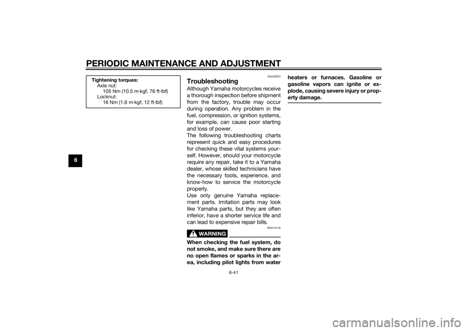
Tightenin g torques:
Axle nut:
105 Nm (10.5 m·kgf, 76 ft·lbf)
Locknut:
16 Nm (1.6 m·kgf, 12 ft·lbf)
U1WSE0E0.book Page 41 Wednesday, November 13, 2013 10:28 AM