meter unit YAMAHA MT-07 2014 Owners Manual
[x] Cancel search | Manufacturer: YAMAHA, Model Year: 2014, Model line: MT-07, Model: YAMAHA MT-07 2014Pages: 106, PDF Size: 3.29 MB
Page 6 of 106

TABLE OF CONTENTSSAFETY INFORMATION.................. 1-1
DESCRIPTION .................................. 2-1
Left view ......................................... 2-1
Right view ....................................... 2-2
Controls and instruments ............... 2-3
INSTRUMENT AND CONTROL
FUNCTIONS ...................................... 3-1
Immobilizer system......................... 3-1
Main switch/steering lock............... 3-2
Indicator lights and warning lights............................................ 3-3
Multi-function meter unit ................ 3-6
Handlebar switches ...................... 3-13
Clutch lever .................................. 3-14
Shift pedal .................................... 3-14
Brake lever.................................... 3-14
Brake pedal .................................. 3-15
ABS (for ABS models) .................. 3-15
Fuel tank cap ................................ 3-16
Fuel ............................................... 3-17
Fuel tank breather hose and
overflow hose ............................ 3-18
Catalytic converter ....................... 3-19
Seats ............................................ 3-19
Helmet holding cable.................... 3-21
Storage compartment .................. 3-22
Adjusting the shock absorber assembly ................................... 3-23
Luggage strap holders ................. 3-24 Sidestand ...................................... 3-24
Ignition circuit cut-off system ....... 3-25
Auxiliary DC connector ................. 3-27
FOR YOUR SAFETY –
PRE-OPERATION CHECKS ............. 4-1
OPERATION AND IMPORTANT
RIDING POINTS ................................ 5-1
Starting the engine .......................... 5-1
Shifting ............................................ 5-2
Tips for reducing fuel consumption ................................ 5-3
Engine break-in ............................... 5-3
Parking ............................................ 5-4
PERIODIC MAINTENANCE AND
ADJUSTMENT ................................... 6-1
Owner’s tool kit ............................... 6-2
Periodic maintenance chart for the emission control system .............. 6-3
General maintenance and lubrication chart ........................... 6-4
Checking the spark plugs ............... 6-8
Engine oil and oil filter cartridge...... 6-9
Coolant.......................................... 6-11
Replacing the air filter element and cleaning the check hose..... 6-14
Checking the throttle grip free
play ............................................ 6-15
Valve clearance ............................. 6-15 Tires .............................................. 6-15
Cast wheels .................................. 6-18
Adjusting the clutch lever free
play ............................................ 6-18
Checking the brake lever free
play ............................................ 6-19
Brake light switches ..................... 6-19
Checking the front and rear brake pads .......................................... 6-20
Checking the brake fluid level ...... 6-21
Changing the brake fluid .............. 6-22
Drive chain slack........................... 6-22
Cleaning and lubricating the drive chain.......................................... 6-24
Checking and lubricating the cables ........................................ 6-25
Checking and lubricating the
throttle grip and cable ............... 6-25
Checking and lubricating the brake and shift pedals............... 6-25
Checking and lubricating the brake and clutch levers ............. 6-26
Checking and lubricating the
sidestand................................... 6-27
Lubricating the rear suspension ... 6-27
Lubricating the swingarm pivots......................................... 6-27
Checking the front fork ................. 6-28
Checking the steering................... 6-28
Checking the wheel bearings ....... 6-29
Battery .......................................... 6-29U1WSE0E0.book Page 1 Wednesday, November 13, 2013 10:28 AM
Page 15 of 106
DESCRIPTION
2-3
2
EAU10431
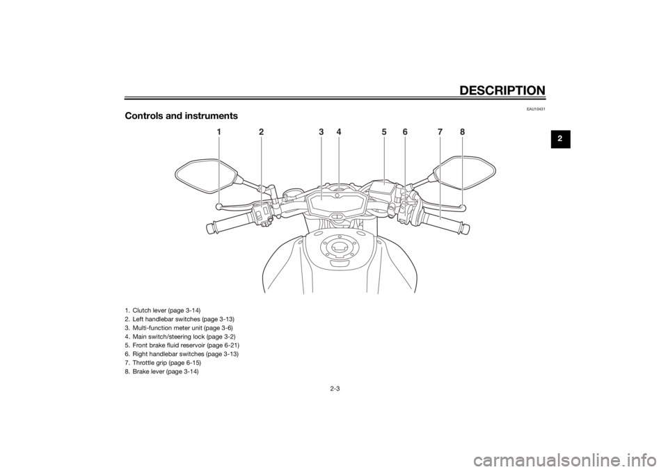
Controls and instruments
1
2
3
4
5
6
7
8
1. Clutch lever (page 3-14)
2. Left handlebar switches (page 3-13)
3. Multi-function meter unit (page 3-6)
4. Main switch/steering lock (page 3-2)
5. Front brake fluid reservoir (page 6-21)
6. Right handlebar switches (page 3-13)
7. Throttle grip (page 6-15)
8. Brake lever (page 3-14)
U1WSE0E0.book Page 3 Wednesday, November 13, 2013 10:28 AM
Page 21 of 106
INSTRUMENT AND CONTROL FUNCTIONS
3-6
3
EAU59973
Multi-function meter unit
WARNING
EWA12423
Be sure to stop the vehicle before
makin g any settin g chan ges to the
multi-function meter unit. Chan gin g
settin gs while ri din g can distract the
operator an d increase the risk of an
acci dent.The multi-function meter unit is
equipped with the following:
a speedometer
a tachometer
a clock
a fuel meter
an eco indicator
a transmission gear display
a multi-function display
a self-diagnosis device
a brightness control mode
TIPBe sure to turn the key to “ON” be-
fore using the left and right set
buttons except for setting the
brightness control mode.
For the U.K. only: To switch the
speedometer and multi-function
display between kilometers and
miles, set the multi-function dis-
play to the odometer mode or a
tripmeter mode, and then press
the left set button for at least three
seconds.Speed ometer
The speedometer shows the vehicle’s
traveling speed.
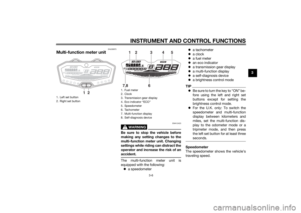
1. Left set button
2. Right set button
1
2
1. Fuel meter
2. Clock
3. Transmission gear display
4. Eco indicator “ECO”
5. Speedometer
6. Tachometer
7. Multi-function display
8. Self-diagnosis device
6
7,8
2
1
3
4
5
U1WSE0E0.book Page 6 Wednesday, November 13, 2013 10:28 AM
Page 27 of 106
INSTRUMENT AND CONTROL FUNCTIONS
3-12
3
If a problem is detected in the immobi-
lizer system circuits, the immobilizer
system indicator light will flash and the
display will indicate an error code.
TIPIf the display indicates error code 52,
this could be caused by transponder
interference. If this error code appears,
try the following.1. Use the code re-registering key to
start the engine.TIPMake sure there are no other immobi-
lizer keys close to the main switch, and
do not keep more than one immobilizer
key on the same key ring! Immobilizer
system keys may cause signal interfer-
ence, which may prevent the engine
from starting.2. If the engine starts, turn it off andtry starting the engine with the
standard keys.
3. If one or both of the standard keys do not start the engine, take the
vehicle, the code re-registering key and both standard keys to a
Yamaha dealer and have the stan- dard keys re-registered.
NOTICE
ECA11591
If the display in dicates an error
co de, the vehicle shoul d b e checked
as soon as possi ble in or der to avoi d
en gine damag e.Brightness control mo de
This function allows you to adjust the
brightness of the multi-function meter
unit panel to suit the outside lighting
conditions.
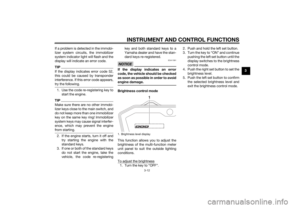
To adjust the brightness1. Turn the key to “OFF”. 2. Push and hold the left set button.
3. Turn the key to “ON” and continue
pushing the left set button until the
display switches to the brightness
control mode.
4. Push the right set button to set the brightness level.
5. Push the left set button to confirm the selected brightness level and
exit the brightness control mode.1. Brightness level display
1
U1WSE0E0.book Page 12 Wednesday, November 13, 2013 10:28 AM
Page 99 of 106

SPECIFICATIONS
8-3
8
Battery:Model:YTZ10S
Voltage, capacity:
12 V, 8.6 AhHea dlig ht:Bulb type:
Halogen bulbBul b volta ge, watta ge × quantity:Headlight:
12 V, 60.0 W/55.0 W × 1
Tail/brake light: LED
Front turn signal light:
12 V, 10.0 W × 2
Rear turn signal light: 12 V, 10.0 W × 2
Auxiliary light: 12 V, 5.0 W × 1
License plate light:
12 V, 5.0 W × 1
Meter lighting: LED
Neutral indicator light: LED
High beam indicator light:
LED
Oil pressure warning light: LED
Turn signal indicator light: LED
Coolant temperature warning light:
LED Engine trouble warning light:
LED
ABS warning light: MT07A LED
Immobilizer system indicator light:
LED
Fuses:Main fuse:30.0 A
Auxiliary fuse:
2.0 A
Headlight fuse: 15.0 A
Signaling system fuse: 10.0 A
Ignition fuse:
10.0 A
Parking lighting fuse: 7.5 A
Radiator fan fuse: 10.0 A
Fuel injection system fuse:
10.0 A
ABS control unit fuse: MT07A 7.5 A
ABS motor fuse: MT07A 30.0 A
ABS solenoid fuse:
MT07A 20.0 A
Backup fuse: 7.5 A
U1WSE0E0.book Page 3 Wednesday, November 13, 2013 10:28 AM
Page 102 of 106

10-1
10
INDEXAABS (for ABS models) ........................... 3-15
ABS warning light (for ABS models) ....... 3-5
Air filter element and check hose, replacing and cleaning ....................... 6-14
Auxiliary DC connector ......................... 3-27
Auxiliary light bulb, replacing ................ 6-36BBattery .................................................. 6-29
Brake and clutch levers, checking and lubricating .................... 6-26
Brake and shift pedals,
checking and lubricating .................... 6-25
Brake fluid, changing ............................ 6-22
Brake fluid level, checking .................... 6-21
Brake lever ............................................ 3-14
Brake lever free play, checking............. 6-19
Brake light switches.............................. 6-19
Brake pedal........................................... 3-15CCables, checking and lubricating ......... 6-25
Care ........................................................ 7-1
Catalytic converter ................................ 3-19
Clutch lever ........................................... 3-14
Clutch lever free play, adjusting ........... 6-18
Coolant ................................................. 6-11
Coolant temperature warning light ......... 3-4DDimmer switch ...................................... 3-13
Drive chain, cleaning and lubricating .... 6-24
Drive chain slack................................... 6-22EEngine break-in....................................... 5-3
Engine oil and oil filter cartridge ............. 6-9 Engine serial number .............................. 9-1
Engine trouble warning light ................... 3-4
FFront and rear brake pads, checking ... 6-20
Front fork, checking ............................. 6-28
Fuel ....................................................... 3-17
Fuel consumption, tips for reducing ...... 5-3
Fuel tank breather hose and overflow
hose ................................................... 3-18
Fuel tank cap ........................................ 3-16
Fuses, replacing ................................... 6-31HHandlebar switches .............................. 3-13
Hazard switch....................................... 3-13
Headlight bulb, replacing ..................... 6-32
Helmet holding cable ........................... 3-21
High beam indicator light ....................... 3-4
Horn switch .......................................... 3-13IIdentification numbers ............................ 9-1
Ignition circuit cut-off system ............... 3-25
Immobilizer system ................................ 3-1
Immobilizer system indicator light .......... 3-5
Indicator lights and warning lights ......... 3-3LLicense plate light bulb, replacing........ 6-35
Luggage strap holders ......................... 3-24MMain switch/steering lock....................... 3-2
Maintenance and lubrication, periodic ... 6-4
Maintenance, emission control system.................................................. 6-3
Matte color, caution ............................... 7-1
Model label ............................................. 9-1 Multi-function meter unit .........................3-6
NNeutral indicator light ..............................3-4OOil pressure warning light .......................3-4PParking ....................................................5-4
Part locations ..........................................2-1
Pass switch ...........................................3-13RRear suspension, lubricating ................6-27SSafety information ...................................1-1
Seats .....................................................3-19
Shifting ....................................................5-2
Shift pedal .............................................3-14
Shock absorber assembly, adjusting ....3-23
Sidestand ..............................................3-24
Sidestand, checking and lubricating.....6-27
Spark plugs, checking ............................6-8
Specifications .........................................8-1
Start/Engine stop switch .......................3-13
Starting the engine ..................................5-1
Steering, checking ................................6-28
Storage ...................................................7-3
Storage compartment ...........................3-22
Supporting the motorcycle ...................6-36
Swingarm pivots, lubricating ................6-27TTail/brake light ......................................6-34
Throttle grip and cable,
checking and lubricating ....................6-25
Throttle grip free play, checking ...........6-15
Tires ......................................................6-15
U1WSE0E0.book Page 1 Wednesday, November 13, 2013 10:28 AM