check engine light YAMAHA MT-07 2016 Owners Manual
[x] Cancel search | Manufacturer: YAMAHA, Model Year: 2016, Model line: MT-07, Model: YAMAHA MT-07 2016Pages: 106, PDF Size: 3.31 MB
Page 6 of 106

Table of contentsSafety information ............................ 1-1
Description ....................................... 2-1
Left view ......................................... 2-1
Right view ....................................... 2-2
Controls and instruments ............... 2-3
Instrument an d control functions ... 3-1
Immobilizer system......................... 3-1
Main switch/steering lock............... 3-2
Indicator lights and warning lights............................................ 3-4
Multi-function meter unit ................ 3-6
Handlebar switches ...................... 3-13
Clutch lever .................................. 3-14
Shift pedal .................................... 3-14
Brake lever.................................... 3-14
Brake pedal .................................. 3-15
ABS (for ABS models) .................. 3-15
Fuel tank cap ................................ 3-16
Fuel ............................................... 3-17
Fuel tank breather hose and overflow hose ............................ 3-18
Catalytic converter ....................... 3-18
Seats ............................................ 3-19
Helmet holding cable.................... 3-20
Storage compartment .................. 3-22
Adjusting the shock absorber assembly ................................... 3-22
Luggage strap holders ................. 3-23
Sidestand ..................................... 3-24 Ignition circuit cut-off system ....... 3-25
Auxiliary DC connector ................. 3-27
For your safety – pre-operation
checks ............................................... 4-1
Operation an d important ri din g
points ................................................. 5-1
Starting the engine .......................... 5-1
Shifting ............................................ 5-2
Tips for reducing fuel consumption ................................ 5-4
Engine break-in ............................... 5-4
Parking ............................................ 5-5
Perio dic maintenance an d
a d justment ........................................ 6-1
Owner’s tool kit ............................... 6-2
Periodic maintenance chart for the emission control system .............. 6-3
General maintenance and lubrication chart ........................... 6-4
Checking the spark plugs ............... 6-8
Engine oil and oil filter cartridge...... 6-9
Coolant.......................................... 6-11
Replacing the air filter element
and cleaning the check hose..... 6-14
Checking the throttle grip free play ............................................ 6-15
Valve clearance ............................. 6-15
Tires .............................................. 6-16 Cast wheels .................................. 6-18
Adjusting the clutch lever free
play ............................................ 6-18
Checking the brake lever free play ............................................ 6-19
Brake light switches ..................... 6-20
Checking the front and rear brake pads .......................................... 6-20
Checking the brake fluid level ...... 6-21
Changing the brake fluid .............. 6-22
Drive chain slack........................... 6-23
Cleaning and lubricating the drive chain ................................. 6-24
Checking and lubricating the
cables ........................................ 6-25
Checking and lubricating the throttle grip and cable ............... 6-25
Checking and lubricating the brake and shift pedals............... 6-26
Checking and lubricating the
brake and clutch levers ............. 6-26
Checking and lubricating the sidestand................................... 6-27
Lubricating the rear suspension ... 6-27
Lubricating the swingarm pivots......................................... 6-28
Checking the front fork ................. 6-28
Checking the steering................... 6-29
Checking the wheel bearings ....... 6-29
Battery .......................................... 6-29
Replacing the fuses ...................... 6-31U1WSE3E0.book Page 1 Monday, June 8, 2015 10:12 AM
Page 12 of 106

Safety information
1-5
1operator and may limit control
ability, therefore, such accesso-
ries are not recommended.
Use caution when adding electri-
cal accessories. If electrical ac-
cessories exceed the capacity of
the motorcycle’s electrical sys-
tem, an electric failure could re-
sult, which could cause a
dangerous loss of lights or engine
power.
Aftermarket Tires an d Rims
The tires and rims that came with your
motorcycle were designed to match
the performance capabilities and to
provide the best combination of han-
dling, braking, and comfort. Other
tires, rims, sizes, and combinations
may not be appropriate. Refer to page
6-16 for tire specifications and more in-
formation on replacing your tires.
Transportin g the Motorcycle
Be sure to observe following instruc-
tions before transporting the motorcy-
cle in another vehicle. Remove all loose items from the
motorcycle.
Check that the fuel cock (if
equipped) is in the “OFF” position
and that there are no fuel leaks.
Point the front wheel straight
ahead on the trailer or in the truck
bed, and choke it in a rail to pre-
vent movement.
Shift the transmission in gear (for
models with a manual transmis-
sion).
Secure the motorcycle with tie-
downs or suitable straps that are
attached to solid parts of the mo-
torcycle, such as the frame or up-
per front fork triple clamp (and not,
for example, to rubber-mounted
handlebars or turn signals, or
parts that could break). Choose
the location for the straps carefully
so the straps will not rub against
painted surfaces during transport.
The suspension should be com-
pressed somewhat by the tie-
downs, if possible, so that the mo-
torcycle will not bounce exces-
sively during transport.
U1WSE3E0.book Page 5 Monday, June 8, 2015 10:12 AM
Page 19 of 106
Instrument and control functions
3-4
3
EAU49398
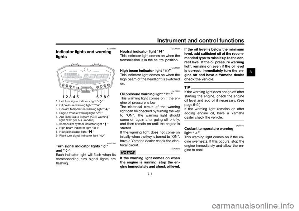
In dicator lig hts and warning
lig hts
EAU11032
Turn si gnal in dicator li ghts “ ”
an d“”
Each indicator light will flash when its
corresponding turn signal lights are
flashing.
EAU11061
Neutral in dicator li ght “ ”
This indicator light comes on when the
transmission is in the neutral position.
EAU11081
Hi gh beam in dicator li ght “ ”
This indicator light comes on when the
high beam of the headlight is switched
on.
EAU59962
Oil pressure warnin g lig ht “ ”
This warning light comes on if the en-
gine oil pressure is low.
The electrical circuit of the warning
light can be checked by turning the key
to “ON”. The warning light should
come on again after going off briefly,
and then remain on until the engine is
started.
If the warning light does not come on
initially when the key is turned to “ON”,
have a Yamaha dealer check the elec-
trical circuit.NOTICE
ECA21210
If the warnin g li ght comes on when
the en gine is runnin g, stop the en-
g ine imme diately an d check oil level. If the oil level is
below the minimum
level, a dd sufficient oil of the recom-
men ded t y p e t o r a i s e i t u p t o t h e c o r -
rect level. If the oil pressure warnin g
li g ht remains on even if the oil level
is correct, immed iately turn the en-
g ine off an d have a Yamaha dealer
check the vehicle.
TIPIf the warning light does not go off after
starting the engine, check the engine
oil level and add oil if necessary. (See
page 6-9.)
If the warning light remains on after
adding engine oil, have a Yamaha
dealer check the vehicle.
EAU11447
Coolant temperature warnin g
li g ht “ ”
This warning light comes on if the en-
gine overheats. If this occurs, stop the
engine immediately and allow the en-
gine to cool.
1. Left turn signal indicator light “ ”
2. Oil pressure warning light “ ”
3. Coolant temperature warning light “ ”
4. Engine trouble warning light “ ”
5. Anti-lock Brake System (ABS) warning light “ ” (for ABS models)
6. Immobilizer system indicator light “ ”
7. High beam indicator light “ ”
8. Neutral indicator light “ ”
9. Right turn signal indicator light “ ”
1
2
3
4
5
6
7
8
9
ABS
U1WSE3E0.book Page 4 Monday, June 8, 2015 10:12 AM
Page 20 of 106
Instrument and control functions
3-5
3 The electrical circuit of the warning
light can be checked by turning the key
to “ON”. The warning light should
come on for a few seconds, and then
go off.
If the warning light does not come on
initially when the key is turned to “ON”,
or if the warning light remains on, have
a Yamaha dealer check the electrical
circuit.
NOTICE
ECA10022
Do not continue to operate the en-
g
ine if it is overheatin g.TIP For radiator-fan-equipped vehi-
cles, the radiator fan(s) automati-
cally switch on or off according to
the coolant temperature in the ra-
diator.
If the engine overheats, see page
6-43 for further instructions.
EAU46443
Engine trou ble warnin g lig ht “ ”
This warning light comes on if a prob-
lem is detected in the electrical circuit
monitoring the engine. If this occurs, have a Yamaha dealer check the self-
diagnosis system. (See page 3-12 for
an explanation of the self-diagnosis
device.)
The electrical circuit of the warning
light can be checked by turning the key
to “ON”. The warning light should
come on for a few seconds, and then
go off.
If the warning light does not come on
initially when the key is turned to “ON”,
or if the warning light remains on, have
a Yamaha dealer check the electrical
circuit.
TIPThis warning light will come on when
the key is turned to “ON” and the start
switch is pushed, but this does not in-
dicate a malfunction.
EAU58530
ABS warnin
g li ght “ ” (for ABS
mo dels)
In normal operation, the ABS warning
light comes on when the key is turned
to “ON”, and goes off after traveling at
a speed of 10 km/h (6 mi/h) or higher.
If the ABS warning light:
does not come on when the key is
turned to “ON”
comes on or flashes while riding
does not go off after traveling at a
speed of 10 km/h (6 mi/h) or high-
er
The ABS may not work correctly. If any
of the above occurs, have a Yamaha
dealer check the system as soon as
possible. (See page 3-15 for an expla-
nation of the ABS.)
WARNING
EWA16041
If the ABS warnin g li ght does not g o
off after travelin g at a speed of 10
km/h (6 mi/h) or hi gher, or if the
warnin g li ght comes on or flashes
while ri din g, the brake system re-
verts to conventional braking . If ei-
ther of the a bove occurs, or if the
warnin g li ght does not come on at
all, use extra caution to avoi d possi-
b le wheel lock durin g emer gency
b rakin g. Have a Yamaha d ealer
check the brake system an d electri-
cal circuits as soon as possi ble.
ABS
U1WSE3E0.book Page 5 Monday, June 8, 2015 10:12 AM
Page 23 of 106
Instrument and control functions
3-8
3
5. Use the right set button to set the
minutes.
6. Push the left set button and then release it to start the clock.
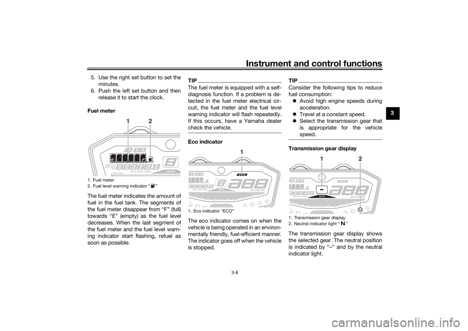
Fuel meter
The fuel meter indicates the amount of
fuel in the fuel tank. The segments of
the fuel meter disappear from “F” (full)
towards “E” (empty) as the fuel level
decreases. When the last segment of
the fuel meter and the fuel level warn-
ing indicator start flashing, refuel as
soon as possible.
TIPThe fuel meter is equipped with a self-
diagnosis function. If a problem is de-
tected in the fuel meter electrical cir-
cuit, the fuel meter and the fuel level
warning indicator will flash repeatedly.
If this occurs, have a Yamaha dealer
check the vehicle.Eco in dicator
The eco indicator comes on when the
vehicle is being operated in an environ-
mentally friendly, fuel-efficient manner.
The indicator goes off when the vehicle
is stopped.
TIPConsider the following tips to reduce
fuel consumption: Avoid high engine speeds during
acceleration.
Travel at a constant speed.
Select the transmission gear that
is appropriate for the vehicle
speed.Transmission gear display
The transmission gear display shows
the selected gear. The neutral position
is indicated by “–” and by the neutral
indicator light.
1. Fuel meter
2. Fuel level warning indicator “ ”
1
2
1. Eco indicator “ECO”
1
1. Transmission gear display
2. Neutral indicator light “ ”
1
2
U1WSE3E0.book Page 8 Monday, June 8, 2015 10:12 AM
Page 27 of 106

Instrument and control functions
3-12
3
Self-d
iagnosis mo de
This model is equipped with a self-di-
agnosis function for various electrical
circuits. If a problem is detected in any
of those circuits, the engine trouble
warning light will come on and the dis-
play changes to self-diagnosis mode. If
the display indicates any error codes,
note the code number and have a
Yamaha dealer check the vehicle. The self-diagnosis function also de-
tects problems with the immobilizer
system. If a problem is detected in the
immobilizer system, the immobilizer
system indicator light will flash and the
display will indicate an error code.
TIPIf the display indicates error code 52,
this could be caused by transponder
interference. Try the following:1. Make sure there are no other im- mobilizer keys close to the main
switch. Other immobilizer system
keys may cause interference and
prevent the engine from starting.
2. Use the code re-registering key to start the engine.
3. If the engine starts, turn it off and try starting the engine with the
standard keys.
4. If one or both of the standard keys do not start the engine, take the
vehicle along with all three keys to
a Yamaha dealer to have them re-
registered.NOTICE
ECA11591
If the display in dicates an error co-
d e, the vehicle shoul d b e checked as
soon as possi ble in or der to avoi d
en gine damag e.
Brightness control mo de
The brightness control mode allows
you to adjust the brightness level of the
multi-function meter unit.
To adjust the brightness1. Turn the key to “OFF”.
2. Push and hold the left set button.
3. Turn the key to “ON” and continue pushing the left set button until the
display switches to the brightness
control mode.
4. Push the right set button to set the brightness level.
5. Push the left set button to confirm the selected brightness level and
exit the brightness control mode.
1. Error code display
2. Engine trouble warning light “ ”
3. Immobilizer system indicator light “ ”
21
3
1. Brightness level display
1
U1WSE3E0.book Page 12 Monday, June 8, 2015 10:12 AM
Page 47 of 106

Operation and important ri din g points
5-2
5
NOTICE
ECA20790
If the a bove warnin g or in dicator
li g hts do not come on initially
when the key is turne d to “ON”,
or if a warnin g or in dicator li ght
(except the oil pressure warnin g
li g ht) remains on, see pa ge 3-4
for the correspon din g warnin g
an d in dicator li ght circuit check.
After goin g off once, the oil
pressure warnin g lig ht will
come back on until the en gine is
starte d. If the warning light does
not come on, or if the warnin g
li g ht does not go off after start-
in g the en gine, see pag e 3-4 for
the en gine oil pressure warnin g
li g ht circuit check.
For ABS models:The ABS warning light should
come on when the key is turned to
“ON”, and then go off after travel-
ing at a speed of 10 km/h (6 mi/h)
or higher.
NOTICE
ECA17682
If the ABS warnin g li ght does not
come on an d then g o off as ex-
plaine d a bove, see pa ge 3-4 for the
warnin g li ght circuit check.2. Shift the transmission into the
neutral position. The neutral indi-
cator light should come on. If not,
ask a Yamaha dealer to check the
electrical circuit.
3. Start the engine by sliding the switch toward “ ”.
If the engine fails to start, release
the start/engine stop switch, wait
a few seconds, and then try again.
Each starting attempt should be
as short as possible to preserve
the battery. Do not crank the en-
gine more than 10 seconds on any
one attempt.NOTICE
ECA11043
For maximum en gine life, never ac-
celerate har d when the en gine is
col d!
EAU16673
Shiftin gShifting gears lets you control the
amount of engine power available for
starting off, accelerating, climbing hills,
etc.
The gear positions are shown in the il-
lustration.TIPTo shift the transmission into the neu-
tral position, press the shift pedal down
repeatedly until it reaches the end of its
travel, and then slightly raise it.1. Shift pedal
2. Neutral position
1
N
2 3
4
5
6
1
2
U1WSE3E0.book Page 2 Monday, June 8, 2015 10:12 AM
Page 58 of 106
Periodic maintenance an d a djustment
6-8
6
EAU19653
Checkin g the spark plu gsThe spark plugs are important engine
components, which should be
checked periodically, preferably by a
Yamaha dealer. Since heat and depos- its will cause any spark plug to slowly
erode, they should be removed and
checked in accordance with the peri-
odic maintenance and lubrication
chart. In addition, the condition of the
spark plugs can reveal the condition of
the engine.
The porcelain insulator around the
center electrode of each spark plug
should be a medium-to-light tan (the
ideal color when the vehicle is ridden
normally), and all spark plugs installed
in the engine should have the same
color. If any spark plug shows a dis-
tinctly different color, the engine could
be operating improperly. Do not at-
tempt to diagnose such problems
yourself. Instead, have a Yamaha deal-
er check the vehicle.
If a spark plug shows signs of elec-
trode erosion and excessive carbon or
other deposits, it should be replaced. Before installing a spark plug, the
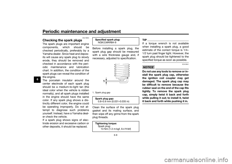
spark plug gap should be measured
with a wire thickness gauge and, if
necessary, adjusted to specification.
Clean the surface of the spark plug
gasket and its mating surface, and
then wipe off any grime from the spark
plug threads.
TIPIf a torque wrench is not available
when installing a spark plug, a good
estimate of the correct torque is 1/4–
1/2 turn past finger tight. However, the
spark plug should be tightened to the
specified torque as soon as possible.NOTICE
ECA10841
Do not use any tools to remove or in-
stall the spark plu
g cap, otherwise
the i gnition coil coupler may get
d amag ed . The spark plu g cap may
b e difficult to remove b ecause the
ru bber seal on the en d of the cap fits
ti g htly. To remove the spark plu g
cap, simply twist it b ack and forth
while pullin g it out; to install it, twist
it back an d forth while pushin g it in.
Specifie d spark plu g:
NGK/LMAR8A-91. Spark plug gapSpark plu g g ap:
0.8–0.9 mm (0.031–0.035 in)
Ti ghtenin g torque:
Spark plug: 13 Nm (1.3 m·kgf, 9.4 ft·lbf)
U1WSE3E0.book Page 8 Monday, June 8, 2015 10:12 AM
Page 59 of 106
Periodic maintenance an d a djustment
6-9
6
EAU60471
En gine oil an d oil filter car-
tri dgeThe engine oil level should be checked
before each ride. In addition, the oil
must be changed and the oil filter car-
tridge replaced at the intervals speci-
fied in the periodic maintenance and
lubrication chart.
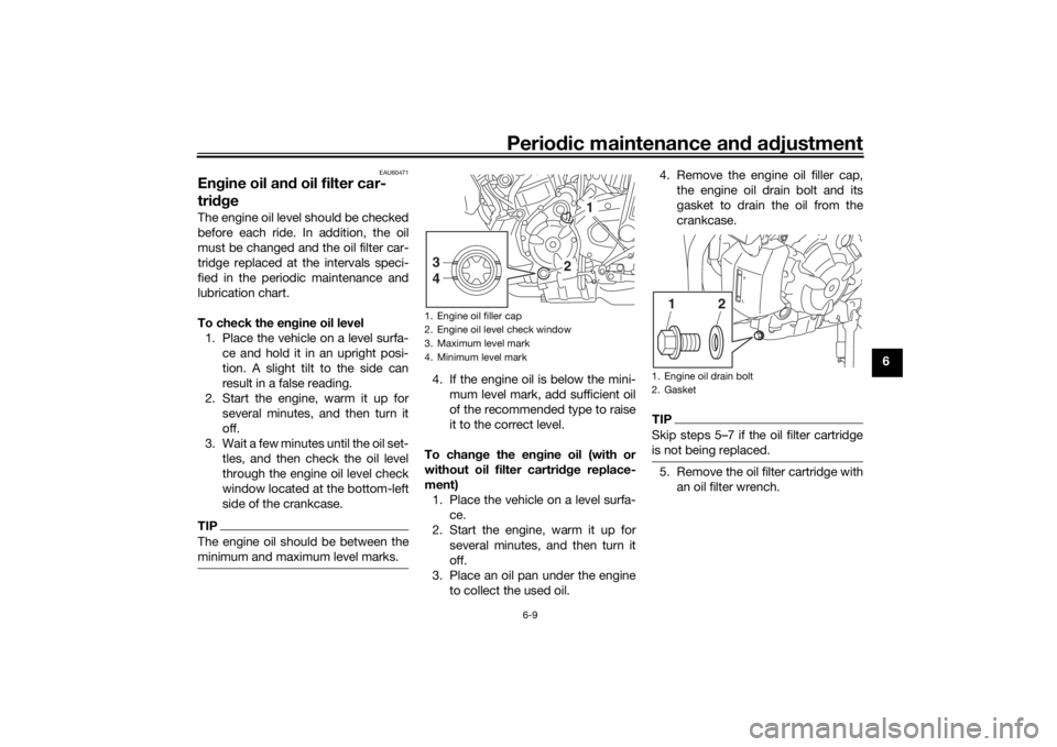
To check the en gine oil level
1. Place the vehicle on a level surfa- ce and hold it in an upright posi-
tion. A slight tilt to the side can
result in a false reading.
2. Start the engine, warm it up for several minutes, and then turn it
off.
3. Wait a few minutes until the oil set- tles, and then check the oil level
through the engine oil level check
window located at the bottom-left
side of the crankcase.TIPThe engine oil should be between the
minimum and maximum level marks.
4. If the engine oil is below the mini-mum level mark, add sufficient oil
of the recommended type to raise
it to the correct level.
To chan ge the en gine oil (with or
without oil filter cartri dge replace-
ment) 1. Place the vehicle on a level surfa- ce.
2. Start the engine, warm it up for several minutes, and then turn it
off.
3. Place an oil pan under the engine to collect the used oil. 4. Remove the engine oil filler cap,
the engine oil drain bolt and its
gasket to drain the oil from the
crankcase.
TIPSkip steps 5–7 if the oil filter cartridge
is not being replaced.5. Remove the oil filter cartridge withan oil filter wrench.
1. Engine oil filler cap
2. Engine oil level check window
3. Maximum level mark
4. Minimum level mark
1
2
3
4
1. Engine oil drain bolt
2. Gasket
2
1
U1WSE3E0.book Page 9 Monday, June 8, 2015 10:12 AM
Page 61 of 106
Periodic maintenance an d a djustment
6-11
6
TIPBe sure to wipe off spilled oil on any
parts after the engine and exhaust sys-
tem have cooled down.NOTICE
ECA11621
In or der to prevent clutch slip-
pa ge (since the en gine oil also
lu bricates the clutch), do not
mix any chemical additives. Do
not use oils with a diesel speci-
fication of “CD” or oils of a hi gh-
er quality than specifie d. In
a ddition, do not use oils lab eled
“ENERGY CONSERVING II” or
hi gher.
Make sure that no forei gn mate-
rial enters the crankcase.
10. Start the engine, and then let it idle for several minutes while checking
it for oil leakage. If oil is leaking,
immediately turn the engine off
and check for the cause.TIPAfter the engine is started, the engine
oil pressure warning light should go off.NOTICE
ECA20860
If the oil pressure warnin g li ght flick-
ers or remains on even if the oil level
is correct, imme diately turn the en-
g ine off an d have a Yamaha dealer
check the vehicle.11. Turn the engine off, wait a few mi- nutes until the oil settles, and then
check the oil level and correct it if
necessary.
EAU20071
CoolantThe coolant level should be checked
before each ride. In addition, the cool-
ant must be changed at the intervals
specified in the periodic maintenance
and lubrication chart.
EAU20095
To check the coolant level1. Place the vehicle on a level surfa- ce and hold it in an upright posi-
tion.TIPThe coolant level must be
checked on a cold engine since
the level varies with engine tem-
perature.
Make sure that the vehicle is posi-
tioned straight up when checking
the coolant level. A slight tilt to the
side can result in a false reading.2. Check the coolant level in the
coolant reservoir.TIPThe coolant should be between the mi-
nimum and maximum level marks.
Recommen ded en gine oil:
See page 8-1.
Oil quantity: Oil change:
2.30 L (2.43 US qt, 2.02 Imp.qt)
With oil filter removal: 2.60 L (2.75 US qt, 2.29 Imp.qt)
U1WSE3E0.book Page 11 Monday, June 8, 2015 10:12 AM