warning YAMAHA MT-07 2018 User Guide
[x] Cancel search | Manufacturer: YAMAHA, Model Year: 2018, Model line: MT-07, Model: YAMAHA MT-07 2018Pages: 100, PDF Size: 5.44 MB
Page 32 of 100
Instrument and control functions
3-17
3
3. Wipe up any spilled fuel immedi-ately. NOTICE: Immediately
wipe off spille d fuel with a clean,
d ry, soft cloth, since fuel may
d eteriorate painted surfaces or
plastic parts.
[ECA10072]
4. Be sure to securely close the fuel tank cap.
WARNING
EWA15152
Gasoline is poisonous an d can
cause injury or death. Han dle gaso-
line with care. Never siphon gasoline
b y mouth. If you shoul d swallow
some gasoline or inhale a lot of gas-
oline vapor, or get some g asoline in
your eyes, see your doctor imme di- ately. If g
asoline spills on your skin,
wash with soap an d water. If gaso-
line spills on your clothin g, chan ge
your clothes.
EAU76860
NOTICE
ECA11401
Use only unlea ded g asoline. The use
of lea ded g asoline will cause severe
d amag e to internal en gine parts,
such as the valves an d piston rin gs,
as well as to the exhaust system.
TIP This mark identifies the recom-
mended fuel for this vehicle as
specified by European regulation
(EN228).
Check that gasoline nozzle has
the same identifier when fueling.Your Yamaha engine has been de-
signed to use regular unleaded gaso-
line with a research octane number of
95 or higher. If knocking (or pinging)
occurs, use a gasoline of a different
brand or premium unleaded fuel. Use
of unleaded fuel will extend spark plug
life and reduce maintenance costs.
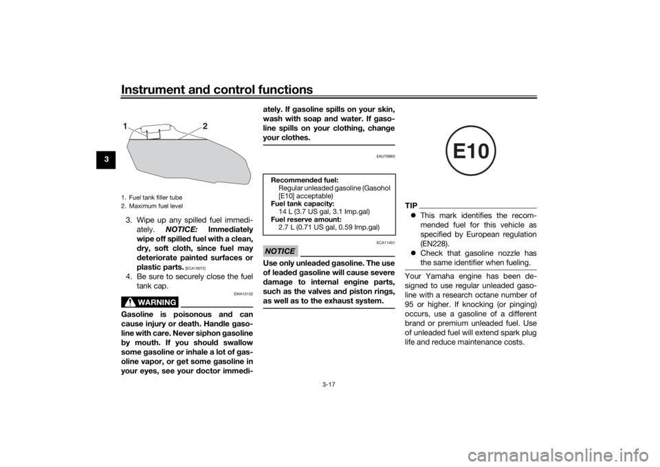
1. Fuel tank filler tube
2. Maximum fuel level
2
1
Recommen ded fuel:
Regular unleaded gasoline (Gasohol
[E10] acceptable)
Fuel tank capacity:
14 L (3.7 US gal, 3.1 Imp.gal)
Fuel reserve amount: 2.7 L (0.71 US gal, 0.59 Imp.gal)
E10
UB4CE0E0.book Page 17 Monday, December 11, 2017 3:53 PM
Page 34 of 100
Instrument and control functions
3-19
3
EAU13434
Catalytic converterThis model is equipped with a catalytic
converter in the exhaust system.
WARNING
EWA10863
The exhaust system is hot after op-
eration. To prevent a fire hazar d or
b urns:
Do not park the vehicle near
possi ble fire hazard s such as
g rass or other materials that
easily burn.
Park the vehicle in a place
where ped estrians or chil dren
are not likely to touch the hot
exhaust system.
Make sure that the exhaust sys-
tem has cooled down before
d oin g any maintenance work.
Do not allow the en gine to i dle
more than a few minutes. Lon g
i d lin g can cause a b uild-up of
heat.
NOTICE
ECA10702
Use only unlea ded g asoline. The use
of lead ed g asoline will cause unre-
pairab le dama ge to the catalytic
converter.
EAU83850
SeatsPassen ger seat
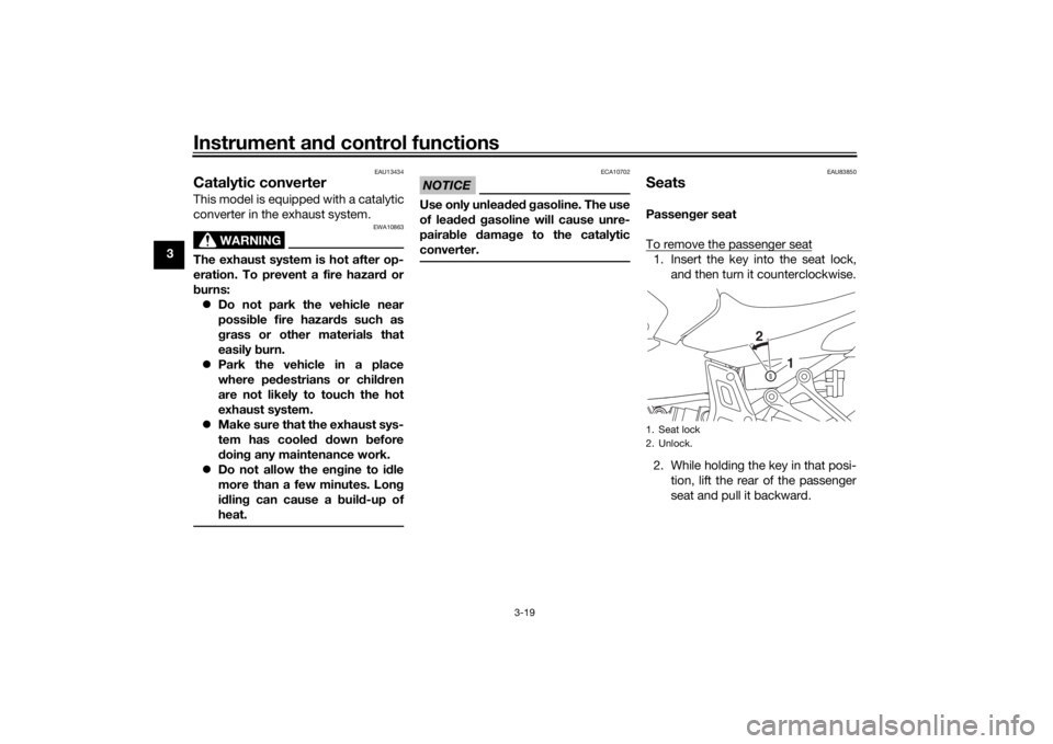
To remove the passenger seat1. Insert the key into the seat lock, and then turn it counterclockwise.
2. While holding the key in that posi- tion, lift the rear of the passenger
seat and pull it backward.1. Seat lock
2. Unlock.
2
1
UB4CE0E0.book Page 19 Monday, December 11, 2017 3:53 PM
Page 36 of 100
Instrument and control functions
3-21
3
EAU59981
Helmet hol din g ca bleA helmet holding cable is located on
the bottom of the passenger seat. Use
this cable in conjunction with the
screwdriver to secure a helmet to the
vehicle.
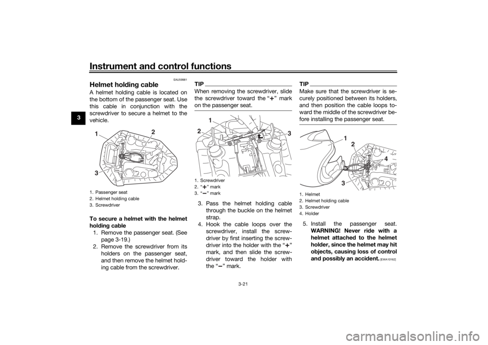
To secure a helmet with the helmet
hol din g cab le
1. Remove the passenger seat. (See page 3-19.)
2. Remove the screwdriver from its holders on the passenger seat,
and then remove the helmet hold-
ing cable from the screwdriver.
TIPWhen removing the screwdriver, slide
the screwdriver toward the “ ” mark
on the passenger seat.3. Pass the helmet holding cablethrough the buckle on the helmet
strap.
4. Hook the cable loops over the screwdriver, install the screw-
driver by first inserting the screw-
driver into the holder with the “ ”
mark, and then slide the screw-
driver toward the holder with
the “ ” mark.
TIPMake sure that the screwdriver is se-
curely positioned between its holders,
and then position the cable loops to-
ward the middle of the screwdriver be-
fore installing the passenger seat.5. Install the passenger seat.WARNING! Never ri de with a
helmet attached to the helmet
hol der, since the helmet may hit
o bjects, causin g loss of control
an d possi bly an acci dent.
[EWA10162]
1. Passenger seat
2. Helmet holding cable
3. Screwdriver1
2
3
1. Screwdriver
2. “ ” mark
3. “ ” mark
1
2
3
1. Helmet
2. Helmet holding cable
3. Screwdriver
4. Holder
1
2
3
4
UB4CE0E0.book Page 21 Monday, December 11, 2017 3:53 PM
Page 37 of 100
Instrument and control functions
3-22
3
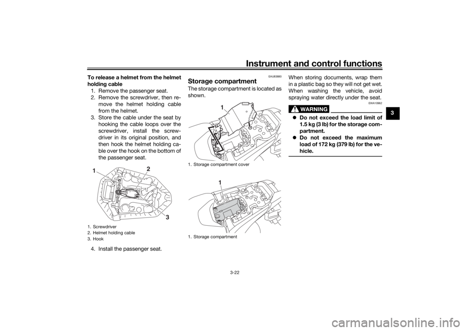
To release a helmet from the helmet
hol
din g cab le
1. Remove the passenger seat.
2. Remove the screwdriver, then re- move the helmet holding cable
from the helmet.
3. Store the cable under the seat by hooking the cable loops over the
screwdriver, install the screw-
driver in its original position, and
then hook the helmet holding ca-
ble over the hook on the bottom of
the passenger seat.
4. Install the passenger seat.
EAU83880
Stora ge compartmentThe storage compartment is located as
shown. When storing documents, wrap them
in a plastic bag so they will not get wet.
When washing the vehicle, avoid
spraying water directly under the seat.
WARNING
EWA10962
Do not exceed the load limit of
1.5 k g (3 l b) for the stora ge com-
partment.
Do not excee d the maximum
loa d of 172 k g (379 l b) for the ve-
hicle.
1. Screwdriver
2. Helmet holding cable
3. Hook1
2
3
1. Storage compartment cover
1. Storage compartment
11
UB4CE0E0.book Page 22 Monday, December 11, 2017 3:53 PM
Page 39 of 100
Instrument and control functions
3-24
3
TIPTo obtain a precise adjustment, it is
advisable to check the actual total
number of turns of the damping force
adjusting mechanism. This adjustment
range may not exactly match the spec-
ifications listed due to small differenc-
es in production.
WARNING
EWA10222
This shock a bsor ber assem bly con-
tains hig hly pressurize d nitro gen
g as. Rea d an d un derstan d the fol-
lowin g information before han dlin g
the shock ab sorber assem bly.
Do not tamper with or attempt
to open the cylin der assem bly.
Do not su bject the shock a b-
sor ber assem bly to an open
flame or other hi gh heat source.
This may cause the unit to ex-
plod e due to excessive gas
pressure.
Do not d eform or damag e the
cylin der in any way. Cylin der
d amag e will result in poor
d ampin g performance.
Do not dispose of a damag ed or
worn-out shock a bsor ber
as-
sem bly yourself. Take the shock
a b sor ber assem bly to a Yamaha
d ealer for any service.
EAU38963
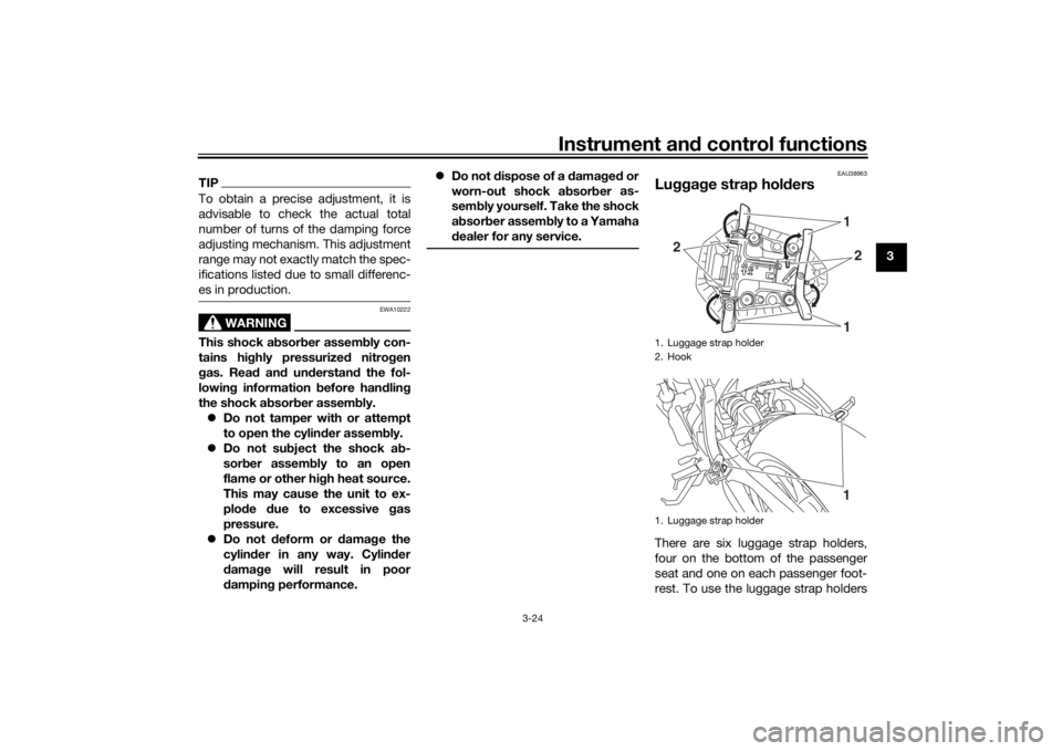
Lu gga ge strap hol dersThere are six luggage strap holders,
four on the bottom of the passenger
seat and one on each passenger foot-
rest. To use the luggage strap holders1. Luggage strap holder
2. Hook
1. Luggage strap holder
12
2
11
UB4CE0E0.book Page 24 Monday, December 11, 2017 3:53 PM
Page 40 of 100
Instrument and control functions
3-25
3 on the passenger seat, remove the
passenger seat. (See page 3-19.) Un-
hook the straps from the hooks, and
then install the seat with the straps
hanging out from under the passenger
seat.
EAU70641
Auxiliary DC connectorThis vehicle is equipped with an auxil-
iary DC connector. Consult your
Yamaha dealer before installing any accessories.
EAU15306
Si destan dThe sidestand is located on the left
side of the frame. Raise the sidestand
or lower it with your foot while holding
the vehicle upright.TIPThe built-in sidestand switch is part of
the ignition circuit cut-off system,
which cuts the ignition in certain situa-
tions. (See the following section for an
explanation of the ignition circuit cut-
off system.)
WARNING
EWA10242
The vehicle must not be ri dden with
the si destan d d own, or if the si de-
stan d cannot b e properly moved up
(or does not stay up), otherwise the
si destan d coul d contact the groun d
an d d istract the operator, resultin g
in a possi ble loss of control.
Yamaha’s i gnition circuit cut-off
system has been desi gne d to assist
the operator in fulfillin g the respon-
si bility of raisin g the si destan d b e-
fore startin g off. Therefore, check
UB4CE0E0.book Page 25 Monday, December 11, 2017 3:53 PM
Page 42 of 100
Instrument and control functions
3-27
3
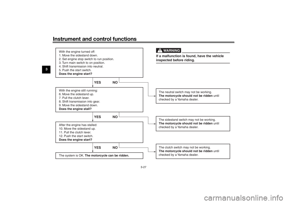
With the engine turned off:
1. Move the sidestand down.
2. Set engine stop switch to run position.
3. Turn main switch to on position.
4. Shift transmission into neutral.
5. Push the start switch.
Does the engine start?
With the engine still running:
6. Move the sidestand up.
7. Pull the clutch lever.
8. Shift transmission into gear.
9. Move the sidestand down.
Does the engine stall?
After the engine has stalled:
10. Move the sidestand up.
11. Pull the clutch lever.
12. Push the start switch.
Does the engine start?
The system is OK. The motorcycle can be ridden.
YES NO YES NO YES NO
The neutral switch may not be working.
The motorcycle should not be ridden until
checked by a Yamaha dealer.
The clutch switch may not be working.
The motorcycle should not be ridden until
checked by a Yamaha dealer.The sidestand switch may not be working.
The motorcycle should not be ridden until
checked by a Yamaha dealer.If a malfunction is found, have the vehicle
inspected before riding.
WARNING
UB4CE0E0.book Page 27 Monday, December 11, 2017 3:53 PM
Page 43 of 100
For your safety – pre-operation checks
4-1
4
EAU15599
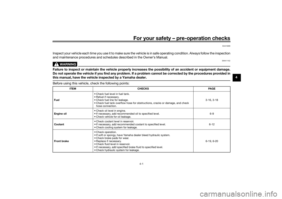
Inspect your vehicle each time you use it to make sure the vehicle is in safe operating condition. Always follow the inspection
and maintenance procedures and schedules described in the Owner’s Manual.
WARNING
EWA11152
Failure to inspect or maintain the vehicle properly increases the possibility of an acci dent or equipment damag e.
Do not operate the vehicle if you fin d any pro blem. If a pro blem cannot be corrected b y the proce dures provi ded in
this manual, have the vehicle inspecte d b y a Yamaha dealer.Before using this vehicle, check the following points:
ITEM CHECKS PAGE
Fuel • Check fuel level in fuel tank.
• Refuel if necessary.
• Check fuel line for leakage.
• Check fuel tank overflow hose for obstructions, cracks or damage, and check
hose connection. 3-16, 3-18
En gine oil • Check oil level in engine.
• If necessary, add recommended oil to specified level.
• Check vehicle for oil leakage. 6-9
Coolant • Check coolant level in reservoir.
• If necessary, add recommended coolant to specified level.
• Check cooling system for leakage. 6-12
Front brake • Check operation.
• If soft or spongy, have Yamaha dealer bleed hydraulic system.
• Check brake pads for wear.
• Replace if necessary.
• Check fluid level in reservoir.
• If necessary, add specified brake fluid to specified level.
• Check hydraulic system for leakage. 6-19, 6-20
UB4CE0E0.book Page 1 Monday, December 11, 2017 3:53 PM
Page 46 of 100
Operation and important rid ing points
5-1
5
EAU15952
Read the Owner’s Manual carefully to
become familiar with all controls. If
there is a control or function you do not
understand, ask your Yamaha dealer.
WARNING
EWA10272
Failure to familiarize yourself with
the controls can lead to loss of con-
trol, which coul d cause an acci dent
or injury.
EAUM3631
TIPThis model is equipped with: a lean angle sensor to stop the en-
gine in case of a turnover. In this
case, the engine trouble warning
light will come on, but this is not a
malfunction. Turn the key to
“OFF” and then to “ON” to turn off
the warning light. Failing to do so
will prevent the engine from start-
ing even though the engine will
crank when pushing the start
switch.
an engine auto-stop system. The
engine stops automatically if left
idling for 20 minutes. If the engine
stops, simply push the start
switch to restart the engine.
EAU83331
Startin g the en gineUnder normal conditions, shift the
transmission into neutral before start-
ing the engine. To start the engine with
the transmission in gear, the sidestand
must be up and the clutch lever pulled.
To start the engine1. Turn the main switch to “ON”, and
set the engine stop switch to “ ”.
2. Confirm the following lights per- form a circuit check. Coolant temperature warning
light
Engine trouble warning light
Oil pressure warning light
ABS warning light
Immobilizer system indicator
lightTIPThe oil pressure warning light
should come back on and stay on
until the engine is started.
The ABS warning light should go
off after reaching a speed of 10
km/h (6 mi/h) or higher.
UB4CE0E0.book Page 1 Monday, December 11, 2017 3:53 PM
Page 49 of 100
Operation and important ri din g points
5-4
5
EAU17214
Parkin gWhen parking, stop the engine, and
then remove the key from the main
switch.
WARNING
EWA10312
Since the en gine an d exhaust
system can b ecome very hot,
park in a place where pe destri-
ans or chil dren are not likely to
touch them an d b e burne d.
Do not park on a slope or on soft
groun d, otherwise the vehicle
may overturn, increasin g the
risk of a fuel leak an d fire.
Do not park near grass or other
flamma ble materials which
mi ght catch fire.
UB4CE0E0.book Page 4 Monday, December 11, 2017 3:53 PM