ECO mode YAMAHA MT-07 2020 Owners Manual
[x] Cancel search | Manufacturer: YAMAHA, Model Year: 2020, Model line: MT-07, Model: YAMAHA MT-07 2020Pages: 100, PDF Size: 5.73 MB
Page 12 of 100

Safety information
1-5
1operator and may limit control
ability, therefore, such accesso-
ries are not recommended.
Use caution when adding electri-
cal accessories. If electrical ac-
cessories exceed the capacity of
the motorcycle’s electrical sys-
tem, an electric failure could re-
sult, which could cause a
dangerous loss of lights or engine
power.
Aftermarket Tires an d Rims
The tires and rims that came with your
motorcycle were designed to match
the performance capabilities and to
provide the best combination of han-
dling, braking, and comfort. Other
tires, rims, sizes, and combinations
may not be appropriate. See page 6-16
for tire specifications and for informa-
tion on servicing and replacing your
tires.
Transportin g the Motorcycle
Be sure to observe following instruc-
tions before transporting the motorcy-
cle in another vehicle.
Remove all loose items from the
motorcycle.
Check that the fuel cock (if
equipped) is in the off position and
that there are no fuel leaks.
Shift the transmission into gear
(for models with a manual trans-
mission).
Secure the motorcycle with tie-
downs or suitable straps that are
attached to solid parts of the mo-
torcycle, such as the frame or up-
per front fork triple clamp (and not,
for example, to rubber-mounted
handlebars or turn signals, or
parts that could break). Choose
the location for the straps carefully
so the straps will not rub against
painted surfaces during transport.
The suspension should be com-
pressed somewhat by the tie-
downs, if possible, so that the mo-
torcycle will not bounce exces-
sively during transport.
UB4CE1E0.book Page 5 Friday, August 3, 2018 10:57 AM
Page 23 of 100

Instrument and control functions
3-8
3
cuit, the fuel meter will flash
repeatedly. If this occurs, have a
Yamaha dealer check the vehicle.
Eco indicator
The eco indicator comes on when the
vehicle is being operated in an environ-
mentally friendly, fuel-efficient manner.
The indicator goes off when the vehicle
is stopped.TIPConsider the following tips to reduce
fuel consumption: Avoid high engine speeds during
acceleration.
Travel at a constant speed.
Select the transmission gear that
is appropriate for the vehicle
speed.
Transmission gear display
The transmission gear display shows
the selected gear. The neutral position
is indicated by “–” and by the neutral
indicator light. Multi-function display
The multi-function display is equipped
with the following:
odometer
two tripmeters
fuel reserve tripmeter
instantaneous fuel consumption
average fuel consumption
coolant temperature
air temperature
brightness control mode
Navigating the multi-function dis-
play
Push the left set button to change the
display between the odometer “ODO”,
tripmeters “TRIP 1” and “TRIP 2”, in-
stantaneous fuel consumption “km/L”
1. Eco indicator “ECO”
1
1. Transmission gear display
2. Neutral indicator light “ ”
1
2
1. Multi-function display
1
UB4CE2E0.book Page 8 Tuesday, July 2, 2019 4:20 PM
Page 24 of 100

Instrument and control functions
3-9
3or “L/100 km”, average fuel consump-
tion “AVE_ _._ km/L” or “AVE_ _._
L/100 km”, coolant temperature “_ _
°C”, and air temperature “Air_ _ °C” in
the following order:
ODO
→ TRIP 1 → TRIP 2 → km/L or
L/100 km → AVE_ _._ km/L or AVE_ _._
L/100 km → _ _ °C → Air_ _ °C → ODO
For the UK:
Push the left set button to change the
display between the odometer “ODO”,
tripmeters “TRIP 1” and “TRIP 2”, in-
stantaneous fuel consumption “km/L”,
“L/100 km” or “MPG”, average fuel
consumption “AVE_ _._ km/L”, “AVE_
_._ L/100 km” or “AVE_ _._ MPG”,
coolant temperature “_ _ °C”, and air
temperature “Air_ _ °C” in the following
order:
ODO → TRIP 1 → TRIP 2 → km/L,
L/100 km or MPG → AVE_ _._ km/L,
AVE_ _._ L/100 km or AVE_ _._ MPG →
_ _ °C → Air_ _ °C → ODO
TIP Push the right set button to
change the display in the reverse
order.
The fuel reserve tripmeter comes
on automatically, while the bright-
ness control mode is accessed
separately.Odometer and tripmeters
The odometer shows the total distance
traveled by the vehicle.
The tripmeters show the distance trav-
eled since they were last reset.
To reset a tripmeter, use the left set
button to display the tripmeter you
want to reset, the tripmeter will flash for
a few seconds. While the tripmeter is
flashing, push the right set button for
one second.TIPThe odometer will lock at 999999.
The tripmeters will lock at 9999.9
but can be manually reset.
Fuel reserve tripmeter
When the fuel level becomes low, the
last segment of the fuel meter will start
flashing. The fuel reserve tripmeter
“TRIP F” will automatically appear and
start counting the distance traveled
from that point. In this case, push the
left set button to switch the display in
the following order:
TRIP F → km/L or L/100 km → AVE_
_._ km/L or AVE_ _._ L/100 km → _ _
°C → Air_ _ °C → ODO → TRIP 1 →
TRIP 2 → TRIP F
For the UK:
TRIP F → km/L, L/100 km or MPG →
AVE_ _._ km/L, AVE_ _._ L/100 km or
AVE_ _._ MPG → _ _ °C → Air_ _ °C →
ODO → TRIP 1 → TRIP 2 → TRIP FTIP Push the right set button to
change the display in the reverse
order.
UB4CE2E0.book Page 9 Tuesday, July 2, 2019 4:20 PM
Page 45 of 100

Operation and important ri din g points
5-1
5
EAU15952
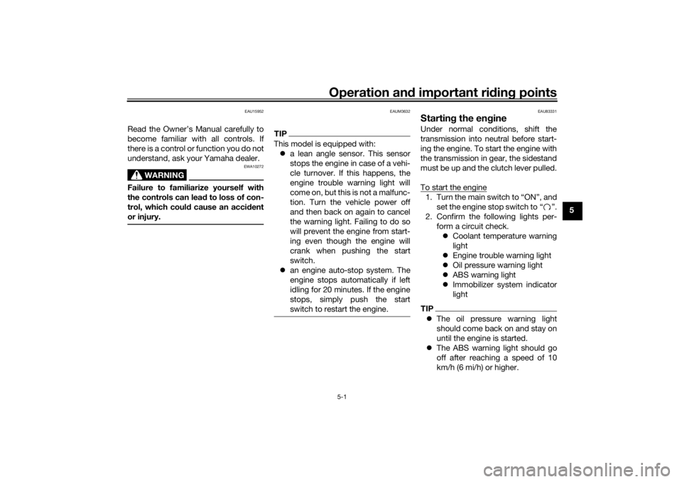
Read the Owner’s Manual carefully to
become familiar with all controls. If
there is a control or function you do not
understand, ask your Yamaha dealer.
WARNING
EWA10272
Failure to familiarize yourself with
the controls can lead to loss of con-
trol, which coul d cause an acci dent
or injury.
EAUM3632
TIPThis model is equipped with: a lean angle sensor. This sensor
stops the engine in case of a vehi-
cle turnover. If this happens, the
engine trouble warning light will
come on, but this is not a malfunc-
tion. Turn the vehicle power off
and then back on again to cancel
the warning light. Failing to do so
will prevent the engine from start-
ing even though the engine will
crank when pushing the start
switch.
an engine auto-stop system. The
engine stops automatically if left
idling for 20 minutes. If the engine
stops, simply push the start
switch to restart the engine.
EAU83331
Startin g the en gineUnder normal conditions, shift the
transmission into neutral before start-
ing the engine. To start the engine with
the transmission in gear, the sidestand
must be up and the clutch lever pulled.
To start the engine1. Turn the main switch to “ON”, and
set the engine stop switch to “ ”.
2. Confirm the following lights per- form a circuit check. Coolant temperature warning
light
Engine trouble warning light
Oil pressure warning light
ABS warning light
Immobilizer system indicator
lightTIP The oil pressure warning light
should come back on and stay on
until the engine is started.
The ABS warning light should go
off after reaching a speed of 10
km/h (6 mi/h) or higher.
UB4CE1E0.book Page 1 Friday, August 3, 2018 10:57 AM
Page 92 of 100

Specifications
8-1
8
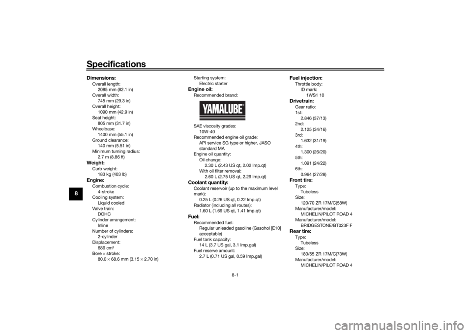
Dimensions:Overall length:2085 mm (82.1 in)
Overall width:
745 mm (29.3 in)
Overall height: 1090 mm (42.9 in)
Seat height: 805 mm (31.7 in)
Wheelbase:
1400 mm (55.1 in)
Ground clearance: 140 mm (5.51 in)
Minimum turning radius: 2.7 m (8.86 ft)Wei ght:Curb weight:
183 kg (403 lb)Engine:Combustion cycle:
4-stroke
Cooling system: Liquid cooled
Valve train: DOHC
Cylinder arrangement:
Inline
Number of cylinders: 2-cylinder
Displacement: 689 cm³
Bore × stroke:
80.0 × 68.6 mm (3.15 × 2.70 in) Starting system:
Electric starter
Engine oil:Recommended brand:
SAE viscosity grades:
10W-40
Recommended engine oil grade:
API service SG type or higher, JASO
standard MA
Engine oil quantity:
Oil change: 2.30 L (2.43 US qt, 2.02 Imp.qt)
With oil filter removal:
2.60 L (2.75 US qt, 2.29 Imp.qt)Coolant quantity:Coolant reservoir (up to the maximum level
mark):0.25 L (0.26 US qt, 0.22 Imp.qt)
Radiator (including all routes): 1.60 L (1.69 US qt, 1.41 Imp.qt)Fuel:Recommended fuel:Regular unleaded gasoline (Gasohol [E10]
acceptable)
Fuel tank capacity: 14 L (3.7 US gal, 3.1 Imp.gal)
Fuel reserve amount: 2.7 L (0.71 US gal, 0.59 Imp.gal)
Fuel injection:Throttle body:ID mark: 1WS1 10Drivetrain:Gear ratio:
1st:2.846 (37/13)
2nd:
2.125 (34/16)
3rd: 1.632 (31/19)
4th: 1.300 (26/20)
5th:
1.091 (24/22)
6th: 0.964 (27/28)Front tire:Type:
Tubeless
Size: 120/70 ZR 17M/C(58W)
Manufacturer/model: MICHELIN/PILOT ROAD 4
Manufacturer/model:
BRIDGESTONE/BT023F FRear tire:Type:Tubeless
Size:
180/55 ZR 17M/C(73W)
Manufacturer/model: MICHELIN/PILOT ROAD 4
UB4CE1E0.book Page 1 Friday, August 3, 2018 10:57 AM
Page 94 of 100

Consumer information
9-1
9
EAU53562
Id entification num bersRecord the vehicle identification num-
ber, engine serial number, and the
model label information in the spaces
provided below. These identification
numbers are needed when registering
the vehicle with the authorities in your
area and when ordering spare parts
from a Yamaha dealer.
VEHICLE IDENTIFICATION NUMBER:
ENGINE SERIAL NUMBER:
MODEL LABEL INFORMATION:
EAU26401
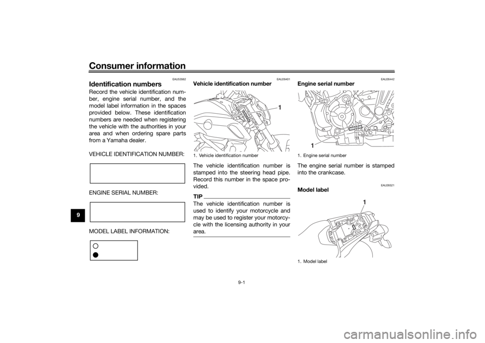
Vehicle i dentification num ber
The vehicle identification number is
stamped into the steering head pipe.
Record this number in the space pro-
vided.TIPThe vehicle identification number is
used to identify your motorcycle and
may be used to register your motorcy-
cle with the licensing authority in your
area.
EAU26442
En gine serial num ber
The engine serial number is stamped
into the crankcase.
EAU26521
Mo del la bel
1. Vehicle identification number
1
1. Engine serial number
1. Model label
1
1
UB4CE1E0.book Page 1 Friday, August 3, 2018 10:57 AM
Page 95 of 100

Consumer information
9-2
9
The model label is affixed to the frame
under the passenger seat. (See page
3-19.) Record the information on this
label in the space provided. This infor-
mation will be needed when ordering
spare parts from a Yamaha dealer.
EAU69910
Dia
gnostic connectorThe diagnostic connector is located as
shown.
EAU85300
Vehicle data recor din gThis model’s ECU stores certain vehi-
cle data to assist in the diagnosis of
malfunctions and for research, statisti-
cal analysis and development purpos-
es.
Although the sensors and recorded
data will vary by model, the main data
points are:
Vehicle status and engine perfor-
mance data
Fuel-injection and emission-relat-
ed data
This data will be uploaded only when a
special Yamaha diagnostic tool is at-
tached to the vehicle, such as when
maintenance checks or service proce-
dures are performed.
Vehicle data uploaded will be handled
appropriately according to the follow-
ing Privacy Policy.
Privacy Policy
1. Diagnostic connector
1
https://www.yamaha-motor.eu/eu/
privacy/privacy-policy.aspx
UB4CE1E0.book Page 2 Friday, August 3, 2018 10:57 AM
Page 97 of 100

10-1
10
Index
AABS....................................................... 3-14
ABS warning light ................................... 3-5
Air filter element and check hose,
replacing and cleaning ....................... 6-15
Auxiliary DC connector ......................... 3-24
Auxiliary light bulb, replacing ............... 6-34BBattery .................................................. 6-29
Brake and clutch levers, checking and lubricating ................................... 6-27
Brake and shift pedals, checking and
lubricating........................................... 6-26
Brake fluid, changing............................ 6-23
Brake fluid level, checking.................... 6-21
Brake lever............................................ 3-13
Brake lever free play, checking ............ 6-20
Brake light switches ............................. 6-20
Brake pedal .......................................... 3-14
Brake/tail light....................................... 6-34CCables, checking and lubricating ......... 6-25
Canister ................................................ 6-10
Care ........................................................ 7-1
Catalytic converter ............................... 3-18
Clutch lever........................................... 3-13
Clutch lever free play, adjusting ........... 6-19
Coolant ................................................. 6-14
Coolant temperature warning light ......... 3-4DData recording, vehicle........................... 9-2
Diagnostic connector ............................. 9-2
Dimmer switch...................................... 3-12
Drive chain, cleaning and lubricating ... 6-25 Drive chain slack .................................. 6-23
EEngine break-in ...................................... 5-4
Engine oil and oil filter cartridge........... 6-10
Engine serial number ............................. 9-1
Engine trouble warning light .................. 3-4FFront and rear brake pads, checking ... 6-21
Front fork, checking ............................. 6-28
Fuel ...................................................... 3-16
Fuel consumption, tips for reducing ...... 5-3
Fuel tank cap........................................ 3-15
Fuel tank overflow hose ....................... 3-17
Fuses, replacing ................................... 6-31HHandlebar switches ............................. 3-12
Hazard switch ...................................... 3-12
Headlight bulb, replacing ..................... 6-32
Helmet holding cable ........................... 3-20
High beam indicator light ....................... 3-4
Horn switch .......................................... 3-12IIdentification numbers ........................... 9-1
Ignition circuit cut-off system .............. 3-25
Immobilizer system ................................ 3-1
Immobilizer system indicator light ......... 3-5
Indicator lights and warning lights ......... 3-3LLicense plate light bulb, replacing ....... 6-35
Luggage strap holders ......................... 3-24MMain switch/steering lock ...................... 3-2
Maintenance and lubrication, periodic... 6-5
Maintenance, emission control
system .................................................. 6-3
Matte color, caution................................ 7-1
Model label ............................................. 9-1
Multi-function meter unit ........................ 3-6
NNeutral indicator light ............................. 3-4OOil pressure warning light ....................... 3-4PParking.................................................... 5-4
Part locations.......................................... 2-1
Pass switch........................................... 3-12SSafety information................................... 1-1
Seats ..................................................... 3-19
Shifting.................................................... 5-2
Shift pedal............................................. 3-13
Shock absorber assembly, adjusting ... 3-22
Sidestand.............................................. 3-25
Sidestand, checking and lubricating .... 6-27
Spark plugs, checking ............................ 6-9
Specifications ......................................... 8-1
Start/Engine stop switch ...................... 3-12
Starting the engine ................................. 5-1
Steering, checking ................................ 6-29
Storage ................................................... 7-3
Storage compartment........................... 3-21
Supporting the motorcycle ................... 6-36
Swingarm pivots, lubricating ................ 6-28TThrottle grip and cable, checking and lubricating ........................................... 6-26
Throttle grip free play, checking ........... 6-16
UB4CE1E0.book Page 1 Friday, August 3, 2018 10:57 AM