light YAMAHA MT-07 2022 User Guide
[x] Cancel search | Manufacturer: YAMAHA, Model Year: 2022, Model line: MT-07, Model: YAMAHA MT-07 2022Pages: 100, PDF Size: 3.66 MB
Page 29 of 100
Instrument and control functions
3-12
3
Ri
ght
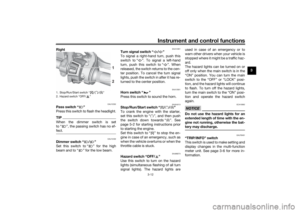
EAU12352
Pass switch “ ”
Press this switch to flash the headlight.TIPWhen the dimmer switch is set
to Ž, the passing switch has no ef-
fect.
EAU12402
Dimmer switch “ / ”
Set this switch to “ ” for the high
beam and to “ ” for the low beam.
EAU12461
Turn si gnal switch “ / ”
To signal a right-hand turn, push this
switch to “ ”. To signal a left-hand
turn, push this switch to “ ”. When
released, the switch returns to the cen-
ter position. To cancel the turn signal
lights, push the switch in after it has re-
turned to the center position.
EAU12501
Horn switch “ ”
Press this switch to sound the horn.
EAU54213
Stop/Run/Start switch “ / / ”
To crank the engine with the starter,
set this switch to “ ”, and then push
the switch down towards “ ”. See
page 5-2 for starting instructions prior
to starting the engine.
Set this switch to “ ” to stop the en-
gine in case of an emergency, such as
when the vehicle overturns or when the
throttle cable is stuck.
EAU88273
Hazar d switch “OFF/ ”
Use this switch to turn on the hazard
lights (simultaneous flashing of all turn
signal lights). The hazard lights are used in case of an emergency or to
warn other drivers when your vehicle is
stopped where it might be a traffic haz-
ard.
The hazard lights can be turned on or
off only when the main switch is in the
“ON” position. You can turn the main
switch to the “OFF” or “LOCK” posi-
tion, and the hazard lights will continue
to flash. To turn off the hazard lights,
turn the main switch to the “ON” posi-
tion and operate the hazard switch
again.
NOTICE
ECA10062
Do not use the hazar
d lig hts for an
exten ded len gth of time with the en-
g ine not runnin g, otherwise the bat-
tery may d ischarge.
EAU78491
“TRIP/INFO” switch
T h i s s w i t c h i s u s e d t o m a k e s e t t i n g a n d
display changes in the multi-function
meter unit. See page 3-6 for more in-
formation.
1. Stop/Run/Start switch “ / / ”
2. Hazard switch “OFF/ ”
1
2
UBATE1E0.book Page 12 Thursday, September 2, 2021 10:34 AM
Page 32 of 100
Instrument and control functions
3-15
3
TIP The ABS performs a self-diagnos-
tic test each time the vehicle first
starts off after the key is turned to
“ON” and the vehicle has traveled
at a speed of 10 km/h (6 mi/h) or
higher. During this test, a “click-
ing” noise can be heard from the
hydraulic control unit, and if the
brake lever or brake pedal is even
slightly applied, a vibration can be
felt at the lever and pedal, but
these do not indicate a malfunc-
tion.
This ABS has a test mode which
allows the owner to experience
the pulsation at the brake lever or
brake pedal when the ABS is op-
erating. However, special tools are
required, so please consult your
Yamaha dealer.NOTICE
ECA20100
Be careful not to damag e the wheel
sensor or wheel sensor rotor; other-
wise, improper performance of the
ABS will result.
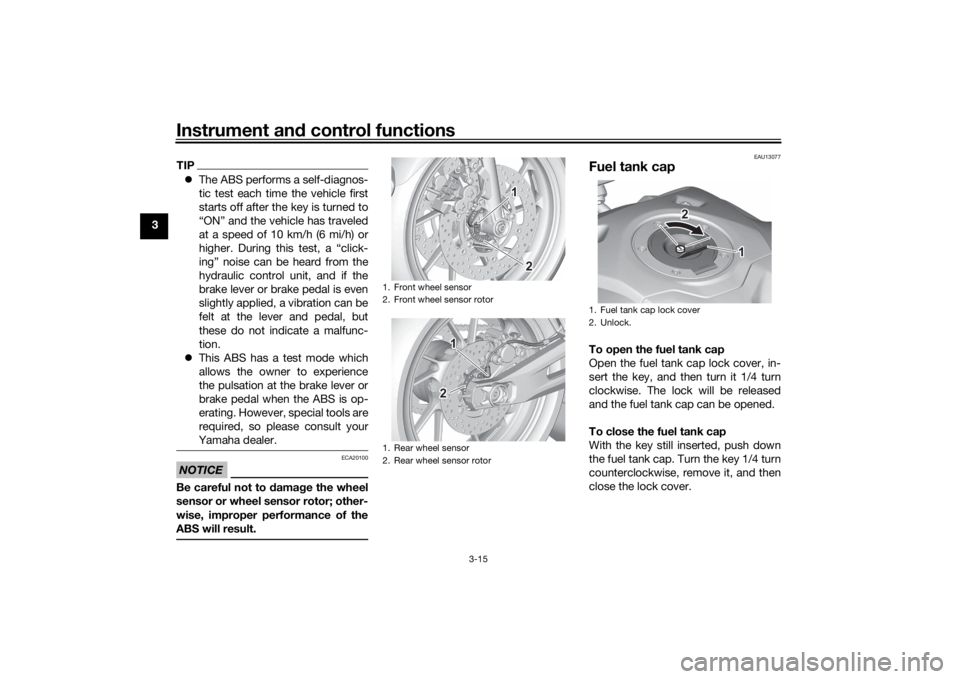
EAU13077
Fuel tank capTo open the fuel tank cap
Open the fuel tank cap lock cover, in-
sert the key, and then turn it 1/4 turn
clockwise. The lock will be released
and the fuel tank cap can be opened.
To close the fuel tank cap
With the key still inserted, push down
the fuel tank cap. Turn the key 1/4 turn
counterclockwise, remove it, and then
close the lock cover.
1. Front wheel sensor
2. Front wheel sensor rotor
1. Rear wheel sensor
2. Rear wheel sensor rotor
1 1 1
2 2
111
222
1. Fuel tank cap lock cover
2. Unlock.
1 1 1
2 2
UBATE1E0.book Page 15 Thursday, September 2, 2021 10:34 AM
Page 33 of 100

Instrument and control functions
3-16
3
TIPThe fuel tank cap cannot be closed un-
less the key is in the lock. In addition,
the key cannot be removed if the cap is
not properly closed and locked.
WARNING
EWA11092
Make sure that the fuel tank cap is
properly closed after filling fuel.
Leakin g fuel is a fire hazar d.
EAU13222
FuelMake sure there is sufficient gasoline in
the tank.
WARNING
EWA10882
Gasoline an d gasoline vapors are
extremely flammab le. To avoid fires
an d explosions an d to re duce the
risk of injury when refueling , follow
these instructions.1. Before refueling, turn off the en- gine and be sure that no one is sit-
ting on the vehicle. Never refuel
while smoking, or while in the vi-
cinity of sparks, open flames, or
other sources of ignition such as
the pilot lights of water heaters
and clothes dryers.
2. Do not overfill the fuel tank. When refueling, be sure to insert the
pump nozzle into the fuel tank filler
hole. Stop filling when the fuel
reaches the bottom of the filler
tube. Because fuel expands when
it heats up, heat from the engine or
the sun can cause fuel to spill out
of the fuel tank. 3. Wipe up any spilled fuel immedi-
ately. NOTICE: Immediately
wipe off spille d fuel with a clean,
d ry, soft cloth, since fuel may
d eteriorate painte d surfaces or
plastic parts.
[ECA10072]
4. Be sure to securely close the fuel tank cap.
WARNING
EWA15152
Gasoline is poisonous an d can
cause injury or death. Han dle gaso-
line with care. Never siphon gasoline
b y mouth. If you shoul d swallow
some gasoline or inhale a lot of g as-
oline vapor, or get some gasoline in
your eyes, see your doctor imme di-1. Fuel tank filler tube
2. Maximum fuel level
2
1
UBATE1E0.book Page 16 Thursday, September 2, 2021 10:34 AM
Page 48 of 100
Operation and important rid ing points
5-2
5
EAU91880
Startin g the eng ineThe ignition circuit cut-off system will
enable starting when:
the transmission is in the neutral
position or
the transmission is in gear, the
sidestand is up, and the clutch le-
ver is pulled.
To start the engine1. Turn the main switch on and set the engine stop switch to the run
position.
2. Confirm the indicator and warning light(s) come on for a few sec-
onds, and then go off. (See page
3-3.)TIPDo not start the engine if the mal-
function indicator light remains on.
The oil pressure warning light
should come on and stay on until
the engine is started.
The ABS warning light should
come on and stay on until the ve-
hicle reaches a speed of 10 km/h
(6 mi/h).
NOTICE
ECA24110
If a warnin g or in dicator li ght does
not work as d escribed a bove, have a
Yamaha dealer check the vehicle.3. Shift the transmission into the
neutral position.
4. Start the engine by pushing the start switch.
5. Release the start switch when the engine starts, or after 5 seconds.
Wait 10 seconds before pressing
the switch again to allow battery
voltage to restore.NOTICE
ECA11043
For maximum en gine life, never ac-
celerate har d when the en gine is
col d!
EAU88780
TIPThis model is equipped with:
a lean angle sensor. This sensor
stops the engine in case of a vehi-
cle turnover. If this happens, the
malfunction indicator light will
come on, but this is not a malfunc-
tion. Turn the vehicle power off
and then back on again to cancel
the indicator light. Failing to do so
will prevent the engine from start-
ing even though the engine will
crank when pushing the start
switch.
an engine auto-stop system. The
engine stops automatically if left
idling for 20 minutes. If the engine
stops, simply push the start
switch to restart the engine.
UBATE1E0.book Page 2 Thursday, September 2, 2021 10:34 AM
Page 49 of 100
Operation and important ri din g points
5-3
5
EAU16675
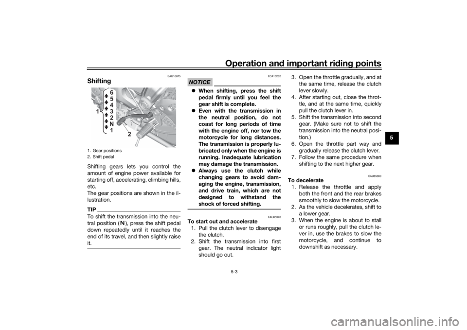
Shiftin gShifting gears lets you control the
amount of engine power available for
starting off, accelerating, climbing hills,
etc.
The gear positions are shown in the il-
lustration.TIPTo shift the transmission into the neu-
tral position ( ), press the shift pedal
down repeatedly until it reaches the
end of its travel, and then slightly raise
it.
NOTICE
ECA10262
When shiftin g, press the shift
pe dal firmly until you feel the
g ear shift is complete.
Even with the transmission in
the neutral position, do not
coast for lon g period s of time
with the en gine off, nor tow the
motorcycle for lon g d istances.
The transmission is properly lu-
b ricated only when the en gine is
runnin g. Ina dequate lu brication
may dama ge the transmission.
Always use the clutch while
chan gin g g ears to avoi d d am-
a g in g the en gine, transmission,
an d d rive train, which are not
d esi gne d to withstan d the
shock of forced shifting.
EAU85370
To start out an d accelerate
1. Pull the clutch lever to disengage the clutch.
2. Shift the transmission into first gear. The neutral indicator light
should go out. 3. Open the throttle gradually, and at
the same time, release the clutch
lever slowly.
4. After starting out, close the throt- tle, and at the same time, quickly
pull the clutch lever in.
5. Shift the transmission into second gear. (Make sure not to shift the
transmission into the neutral posi-
tion.)
6. Open the throttle part way and gradually release the clutch lever.
7. Follow the same procedure when shifting to the next higher gear.
EAU85380
To decelerate
1. Release the throttle and apply both the front and the rear brakes
smoothly to slow the motorcycle.
2. As the vehicle decelerates, shift to a lower gear.
3. When the engine is about to stall or runs roughly, pull the clutch le-
ver in, use the brakes to slow the
motorcycle, and continue to
downshift as necessary.
1. Gear positions
2. Shift pedal
2
1
1
N 2 3
4
5
6
UBATE1E0.book Page 3 Thursday, September 2, 2021 10:34 AM
Page 50 of 100
Operation and important rid ing points
5-4
5 4. Once the motorcycle has
stopped, the transmission can be
shifted into the neutral position.
The neutral indicator light should
come on and then the clutch lever
can be released.
WARNING
EWA17380
Improper brakin g can cause
loss of control or traction. Al-
ways use b oth brakes an d apply
them smoothly.
Make sure that the motorcycle
and the en gine have sufficiently
slowe d b efore shiftin g to a low-
er gear. En gag in g a lower gear
when the vehicle or en gine
speed is too hi gh coul d make
the rear wheel lose traction or
the en gine to over-rev. This
coul d cause loss of control, an
acci dent an d injury. It coul d also
cause en gine or drive train dam-
a g e.
EAU16811
Tips for re ducin g fuel con-
sumptionFuel consumption depends largely on
your riding style. Consider the follow-
ing tips to reduce fuel consumption:
Shift up swiftly, and avoid high en-
gine speeds during acceleration.
Do not rev the engine while shift-
ing down, and avoid high engine
speeds with no load on the en-
gine.
Turn the engine off instead of let-
ting it idle for an extended length
of time (e.g., in traffic jams, at traf-
fic lights or at railroad crossings).
EAU17214
Parkin gWhen parking, stop the engine, and
then remove the key from the main
switch.
WARNING
EWA10312
Since the en gine an d exhaust
system can become very hot,
park in a place where pe destri-
ans or chil dren are not likely to
touch them an d b e burne d.
Do not park on a slope or on soft
groun d, otherwise the vehicle
may overturn, increasin g the
risk of a fuel leak an d fire.
Do not park near grass or other
flammab le materials which
mi ght catch fire.
UBATE1E0.book Page 4 Thursday, September 2, 2021 10:34 AM
Page 58 of 100

Periodic maintenance an d a djustment
6-8
6
EAU72800
TIP Air filter
• This model’s air filter is equipped with a disposable oil-coated paper element, which must not be cleaned with com- pressed air to avoid damaging it.
• The air filter element needs to be replaced more frequently when riding in unusually wet or dusty areas.
Hydraulic brake service
• Regularly check and, if necessary, correct the brake fluid level.
• Every two years replace the internal components of the brake master cylinders and calipers, and change the brake fluid.
• Replace the brake hoses every four years and if cracked or damaged.3 0 *Throttle
grip hous-
in g an d cab le • Check operation and free play.
• Adjust the throttle cable free play
if necessary.
• Lubricate the throttle grip housing and cable. √√√√√
3 1 *Li
ghts, si gnals an d
switches • Check operation.
• Adjust headlight beam.
√√√√√√
NO. ITEM CHECK OR MAINTENANCE JOB
ODOMETER READING
ANNUAL
CHECK
1000 km
(600 mi) 10000 km
(6000 mi) 20000 km
(12000 mi) 3
0000 km
(18000 mi) 40000 km
(24000 mi)UBATE1E0.book Page 8 Thursday, September 2, 2021 10:34 AM
Page 59 of 100
Periodic maintenance an d a djustment
6-9
6
EAU19653
Checkin g the spark plugsThe spark plugs are important engine
components, which should be
checked periodically, preferably by a
Yamaha dealer. Since heat and depos- its will cause any spark plug to slowly
erode, they should be removed and
checked in accordance with the peri-
odic maintenance and lubrication
chart. In addition, the condition of the
spark plugs can reveal the condition of
the engine.
The porcelain insulator around the
center electrode of each spark plug
should be a medium-to-light tan (the
ideal color when the vehicle is ridden
normally), and all spark plugs installed
in the engine should have the same
color. If any spark plug shows a dis-
tinctly different color, the engine could
be operating improperly. Do not at-
tempt to diagnose such problems
yourself. Instead, have a Yamaha deal-
er check the vehicle.
If a spark plug shows signs of elec-
trode erosion and excessive carbon or
other deposits, it should be replaced. Before installing a spark plug, the
spark plug gap should be measured
with a wire thickness gauge and, if
necessary, adjusted to specification.
Clean the surface of the spark plug
gasket and its mating surface, and
then wipe off any grime from the spark
plug threads.
TIPIf a torque wrench is not available
when installing a spark plug, a good
estimate of the correct torque is 1/4…
1/2 turn past finger tight. However, the
spark plug should be tightened to the
specified torque as soon as possible.NOTICE
ECA10841
Do not use any tools to remove or in-
stall the spark plu
g cap, otherwise
the i gnition coil coupler may get
d amag ed . The spark plu g cap may
b e difficult to remove because the
ru bber seal on the en d of the cap fits
ti g htly. To remove the spark plu g
cap, simply twist it b ack and forth
while pullin g it out; to install it, twist
it back an d forth while pushin g it in.
Specified spark plu g:
NGK/LMAR8A-9
1. Spark plug gap
Spark plu g g ap:
0.8–0.9 mm (0.031–0.035 in)
Ti ghtenin g torque:
Spark plug: 13 N·m (1.3 kgf·m, 9.6 lb·ft)
UBATE1E0.book Page 9 Thursday, September 2, 2021 10:34 AM
Page 60 of 100

Periodic maintenance an d a djustment
6-10
6
EAU36113
CanisterThis model is equipped with a canister
to prevent the discharging of fuel vapor
into the atmosphere. Before operating
this vehicle, make sure to check the
following:
Check each hose connection.
Check each hose and canister for
cracks or damage. Replace if
damaged.
Make sure that the canister
breather is not blocked, and if
necessary, clean it.
EAU60474
Engine oil an d oil filter car-
tri dgeThe engine oil level should be checked
before each ride. In addition, the oil
must be changed and the oil filter car-
tridge replaced at the intervals speci-
fied in the periodic maintenance and
lubrication chart.
To check the en gine oil level
1. Place the vehicle on a level sur- face and hold it in an upright posi-
tion. A slight tilt to the side can
result in a false reading.
2. Start the engine, warm it up for several minutes, and then turn it
off.
3. Wait a few minutes for the oil level to settle for an accurate reading,
and then check the oil level
through the engine oil level check
window located at the bottom-left
side of the crankcase.TIPThe engine oil should be between the
minimum and maximum level marks.
4. If the engine oil is below the mini-mum level mark, add sufficient oil
of the recommended type to raise
it to the correct level.TIPCheck the O-ring for damage, and re-
place it if necessary.
1. Canister
2. Canister breather hose
11122
1. Engine oil filler cap
2. Engine oil level check window
3. Maximum level mark
4. Minimum level mark
1 1 1
3
42 2
UBATE1E0.book Page 10 Thursday, September 2, 2021 10:34 AM
Page 62 of 100
Periodic maintenance an d a djustment
6-12
6
8. Install the engine oil drain bolt andits new gasket, and then tighten
the bolt to the specified torque.
9. Refill with the specified amount of the recommended engine oil.
TIPBe sure to wipe off spilled oil on any
parts after the engine and exhaust sys-
tem have cooled down.NOTICE
ECA11621
In or der to prevent clutch slip-
pa ge (since the en gine oil also
lu bricates the clutch), do not
mix any chemical additives. Do
not use oils with a diesel speci-
fication of “CD” or oils of a hi gh-
er quality than specifie d. In
a ddition, do not use oils la beled
“ENERGY CONSERVING II” or
hi gher.
Make sure that no forei gn mate-
rial enters the crankcase.10. Check the O-ring for damage, and replace it if necessary. 11. Install and tighten the engine oil
filler cap.
12. Start the engine, and then let it idle for several minutes while checking
it for oil leakage. If oil is leaking,
immediately turn the engine off
and check for the cause.
TIPAfter the engine is started, the engine
oil pressure warning light should go off.
1. Torque wrenchTightenin g torque:
Oil filter cartridge: 17 N·m (1.7 kgf·m, 13 lb·ft)
Ti ghtenin g torque:
Engine oil drain bolt:
43 N·m (4.3 kgf·m, 32 lb·ft)
1
Recommen ded en gine oil:
See page 8-1.
Oil quantity: Oil change:
2.30 L (2.43 US qt, 2.02 Imp.qt)
With oil filter removal: 2.60 L (2.75 US qt, 2.29 Imp.qt)
1. Engine oil filler cap
2. O-ring
21
UBATE1E0.book Page 12 Thursday, September 2, 2021 10:34 AM