clock YAMAHA MT-07 2022 Owners Manual
[x] Cancel search | Manufacturer: YAMAHA, Model Year: 2022, Model line: MT-07, Model: YAMAHA MT-07 2022Pages: 100, PDF Size: 3.66 MB
Page 23 of 100
Instrument and control functions
3-6
3
EAU92181
Multi-function meter unit
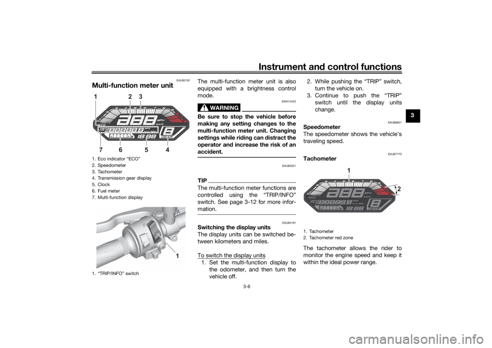
The multi-function meter unit is also
equipped with a brightness control
mode.
WARNING
EWA12423
Be sure to stop the vehicle before
makin g any settin g chan ges to the
multi-function meter unit. Chan gin g
settin gs while ri din g can distract the
operator an d increase the risk of an
acci dent.
EAU92551
TIPThe multi-function meter functions are
switch. See page 3-12 for more infor-
mation.
EAU92191
Switchin g the display units
The display units can be switched be-
tween kilometers and miles.
To switch the display units1. Set the multi-function display to the odometer, and then turn the
vehicle off. 2. While pushing the “TRIP” switch,
turn the vehicle on.
3. Continue to push the “TRIP” switch until the display units
change.
EAU86831
Speed ometer
The speedometer shows the vehicle’s
traveling speed.
EAU87170
Tachometer
The tachometer allows the rider to
monitor the engine speed and keep it
within the ideal power range.
1. Eco indicator “ECO”
2. Speedometer
3. Tachometer
4. Transmission gear display
5. Clock
6. Fuel meter
7. Multi-function display
1. “TRIP/INFO” switch
2
13
6
754
1
1. Tachometer
2. Tachometer red zone
1
2
UBATE1E0.book Page 6 Thursday, September 2, 2021 10:34 AM
Page 24 of 100
Instrument and control functions
3-7
3
NOTICE
ECA10032
Do not operate the en gine in the ta-
chometer red zone.
Re d zone: 10000 r/min an d a bove
EAU86841
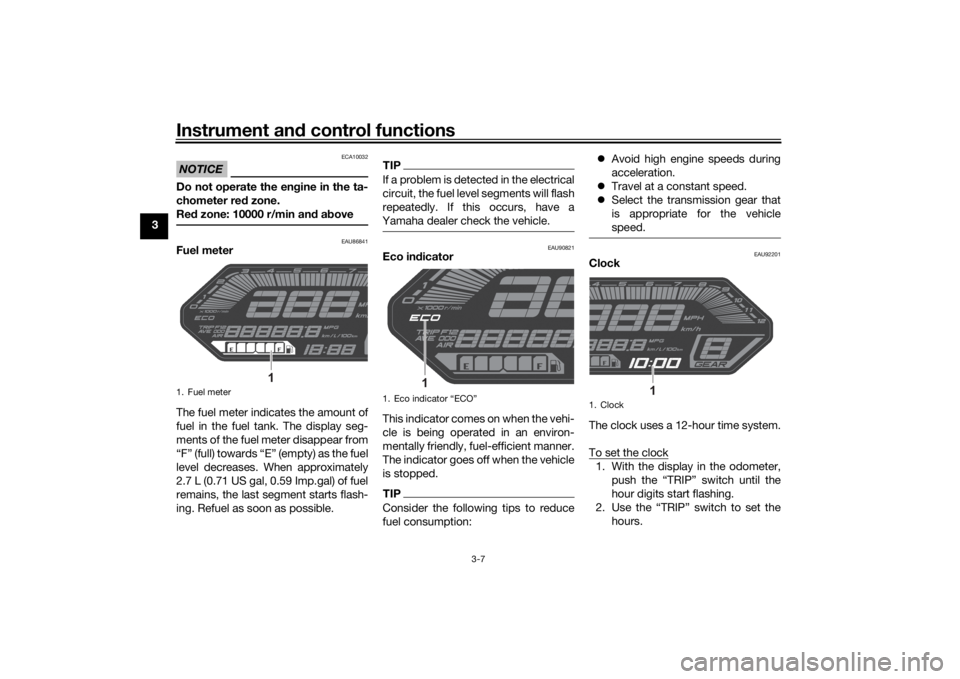
Fuel meter
The fuel meter indicates the amount of
fuel in the fuel tank. The display seg-
ments of the fuel meter disappear from
“F” (full) towards “E” (empty) as the fuel
level decreases. When approximately
2.7 L (0.71 US gal, 0.59 Imp.gal) of fuel
remains, the last segment starts flash-
ing. Refuel as soon as possible.
TIPIf a problem is detected in the electrical
circuit, the fuel level segments will flash
repeatedly. If this occurs, have a
Yamaha dealer check the vehicle.
EAU90821
Eco in dicator
This indicator comes on when the vehi-
cle is being operated in an environ-
mentally friendly, fuel-efficient manner.
The indicator goes off when the vehicle
is stopped.TIPConsider the following tips to reduce
fuel consumption:
Avoid high engine speeds during
acceleration.
Travel at a constant speed.
Select the transmission gear that
is appropriate for the vehicle
speed.
EAU92201
Clock
The clock uses a 12-hour time system.
To set the clock1. With the display in the odometer,
push the “TRIP” switch until the
hour digits start flashing.
2. Use the “TRIP” switch to set the hours.
1. Fuel meter
1
1. Eco indicator
Page 32 of 100
Instrument and control functions
3-15
3
TIP The ABS performs a self-diagnos-
tic test each time the vehicle first
starts off after the key is turned to
“ON” and the vehicle has traveled
at a speed of 10 km/h (6 mi/h) or
higher. During this test, a “click-
ing” noise can be heard from the
hydraulic control unit, and if the
brake lever or brake pedal is even
slightly applied, a vibration can be
felt at the lever and pedal, but
these do not indicate a malfunc-
tion.
This ABS has a test mode which
allows the owner to experience
the pulsation at the brake lever or
brake pedal when the ABS is op-
erating. However, special tools are
required, so please consult your
Yamaha dealer.NOTICE
ECA20100
Be careful not to damag e the wheel
sensor or wheel sensor rotor; other-
wise, improper performance of the
ABS will result.
EAU13077
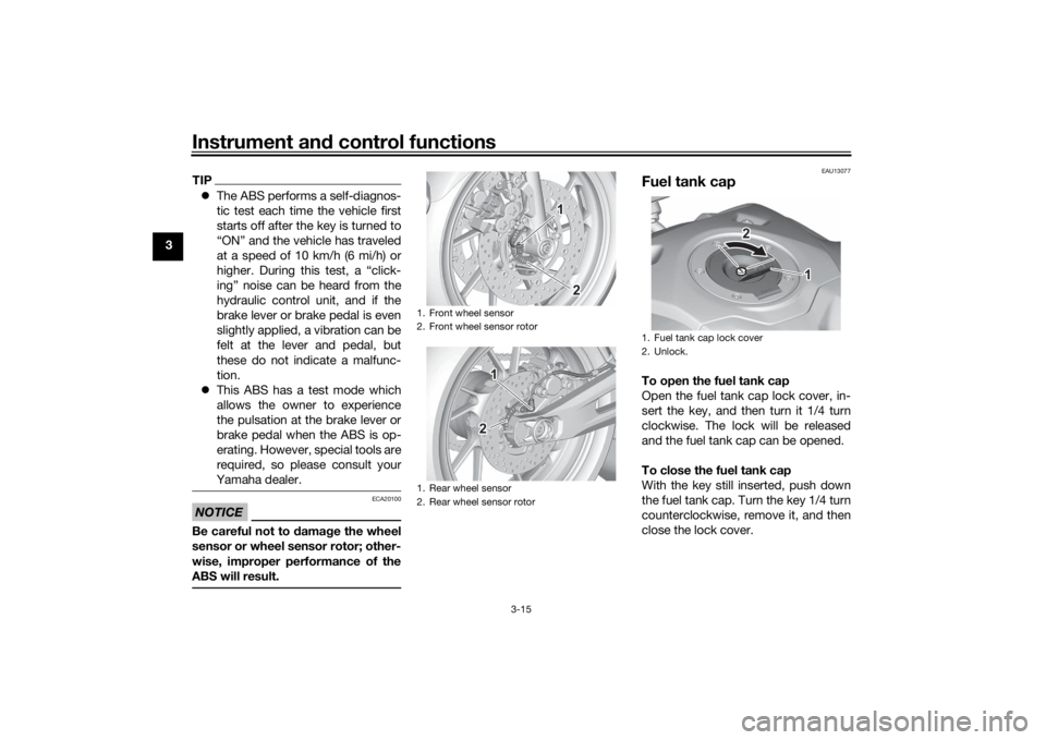
Fuel tank capTo open the fuel tank cap
Open the fuel tank cap lock cover, in-
sert the key, and then turn it 1/4 turn
clockwise. The lock will be released
and the fuel tank cap can be opened.
To close the fuel tank cap
With the key still inserted, push down
the fuel tank cap. Turn the key 1/4 turn
counterclockwise, remove it, and then
close the lock cover.
1. Front wheel sensor
2. Front wheel sensor rotor
1. Rear wheel sensor
2. Rear wheel sensor rotor
1 1 1
2 2
111
222
1. Fuel tank cap lock cover
2. Unlock.
1 1 1
2 2
UBATE1E0.book Page 15 Thursday, September 2, 2021 10:34 AM
Page 36 of 100
Instrument and control functions
3-19
3
EAU83850
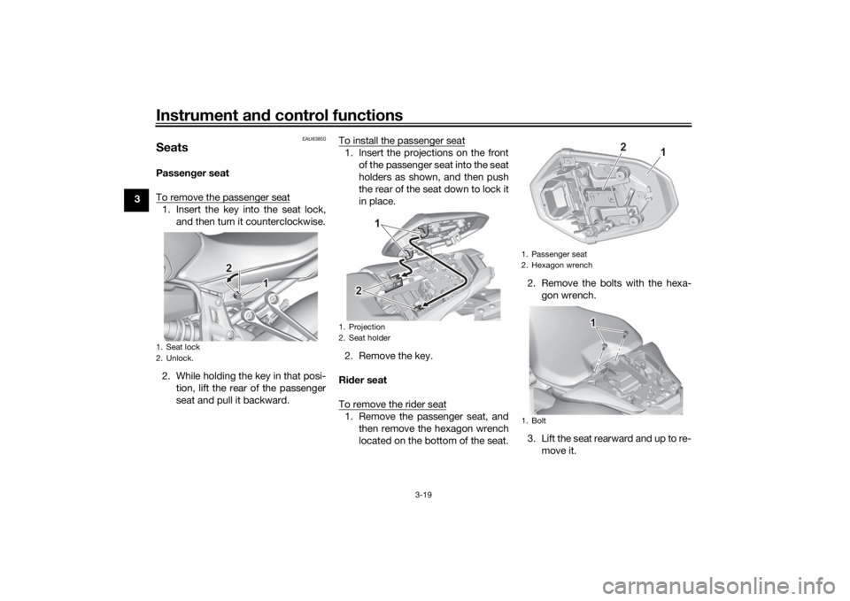
SeatsPassen ger seat
To remove the passenger seat1. Insert the key into the seat lock, and then turn it counterclockwise.
2. While holding the key in that posi- tion, lift the rear of the passenger
seat and pull it backward. To install the passenger seat
1. Insert the projections on the front
of the passenger seat into the seat
holders as shown, and then push
the rear of the seat down to lock it
in place.
2. Remove the key.
Ri der seat
To remove the rider seat1. Remove the passenger seat, and then remove the hexagon wrench
located on the bottom of the seat. 2. Remove the bolts with the hexa-
gon wrench.
3. Lift the seat rearward and up to re- move it.
1. Seat lock
2. Unlock.
111
22
1. Projection
2. Seat holder
222 1
1. Passenger seat
2. Hexagon wrench
1. Bolt
1
2
1 11
UBATE1E0.book Page 19 Thursday, September 2, 2021 10:34 AM
Page 81 of 100
Periodic maintenance an d a djustment
6-31
6
EAU59876
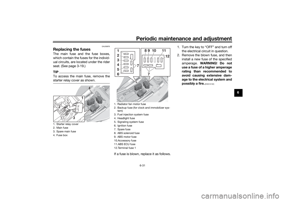
Replacin g the fusesThe main fuse and the fuse boxes,
which contain the fuses for the individ-
ual circuits, are located under the rider
seat. (See page 3-19.)TIPTo access the main fuse, remove the
starter relay cover as shown.
If a fuse is blown, replace it as follows. 1.
the electrical circuit in question.
2. Remove the blown fuse, and then install a new fuse of the specified
amperage. WARNING! Do not
use a fuse of a hi gher ampera ge
ratin g than recommen ded to
avoi d causin g extensive dam-
a g e to the electrical system an d
possi bly a fire.
[EWA15132]
1. Starter relay cover
2. Main fuse
3. Spare main fuse
4. Fuse box
1
2
3
4 4 4
1. Radiator fan motor fuse
2. Backup fuse (for clock and immobilizer sys-tem)
3. Fuel injection system fuse
4. Headlight fuse
5. Signaling system fuse
6. Ignition fuse
7. Spare fuse
8. ABS solenoid fuse
9. ABS motor fuse
10.Accessory fuse
11.ABS ECU fuse
12.Terminal fuse 11 8 9 10 11
12
7
7
2
3
4
5
6
UBATE1E0.book Page 31 Thursday, September 2, 2021 10:34 AM
Page 82 of 100
Periodic maintenance an d a djustment
6-32
6
3. Turn the key to “ON” and turn onthe electrical circuit in question to
check if the device operates.
4. If the fuse immediately blows again, have a Yamaha dealer
check the electrical system.
EAU80380
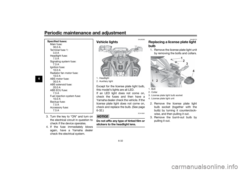
Vehicle lig htsExcept for the license plate light bulb,
this model’s lights are all LED.
If an LED light does not come on,
check the fuses and then have a
Yamaha dealer check the vehicle. If the license plate light does not come on,
check and replace the bulb. (See page
6-32.)NOTICE
ECA16581
Do not affix any type of tinte d film or
stickers to the hea dlig ht lens.
EAU92270
Replacin g a license plate li ght
b ul b1. Remove the license plate light unit
by removing the bolts and collars.
2. Remove the license plate light bulb socket (together with the
bulb) by turning it counterclock-
wise, and then pulling it out.
3. Remove the burnt-out bulb by pulling it out.
Specifie d fuses:
Main fuse:
30.0 A
Terminal fuse 1:
3.0 A
Headlight fuse: 7.5 A
Signaling system fuse: 7.5 A
Ignition fuse:
10.0 A
Radiator fan motor fuse: 10.0 A
ABS motor fuse: 30.0 A
ABS solenoid fuse:
20.0 A
ABS ECU fuse: 7.5 A
Fuel injection system fuse: 10.0 A
Backup fuse:
7.5 A
Accessory fuse: 7.5 A
1. Headlight
2. Auxiliary light
11
2
2
1
22
1. Bolt
2. Collar
3. License plate light bulb socket
4. License plate light unit
111 1
22
2
3
4
UBATE1E0.book Page 32 Thursday, September 2, 2021 10:34 AM
Page 83 of 100
Periodic maintenance an d a djustment
6-33
6
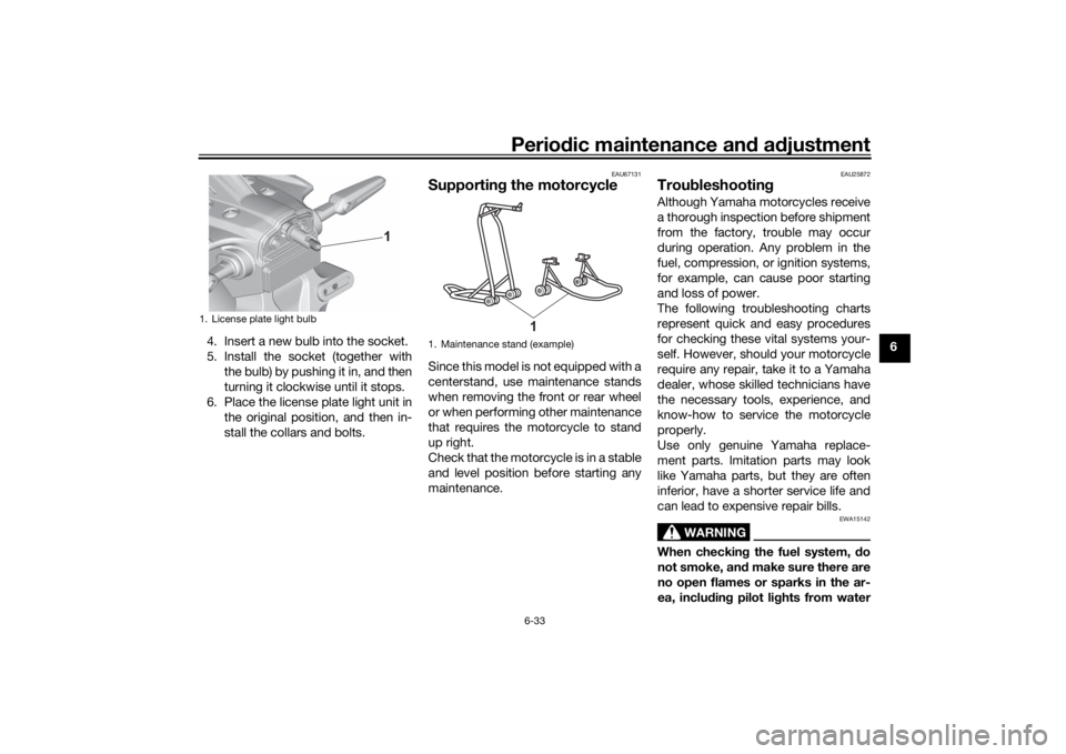
4. Insert a new bulb into the socket.
5. Install the socket (together with
the bulb) by pushing it in, and then
turning it clockwise until it stops.
6. Place the license plate light unit in the original position, and then in-
stall the collars and bolts.
EAU67131
Supportin g the motorcycleSince this model is not equipped with a
centerstand, use maintenance stands
when removing the front or rear wheel
or when performing other maintenance
that requires the motorcycle to stand
up right.
Check that the motorcycle is in a stable
and level position before starting any
maintenance.
EAU25872
Trou bleshootin gAlthough Yamaha motorcycles receive
a thorough inspection before shipment
from the factory, trouble may occur
during operation. Any problem in the
fuel, compression, or ignition systems,
for example, can cause poor starting
and loss of power.
The following troubleshooting charts
represent quick and easy procedures
for checking these vital systems your-
self. However, should your motorcycle
require any repair, take it to a Yamaha
dealer, whose skilled technicians have
the necessary tools, experience, and
know-how to service the motorcycle
properly.
Use only genuine Yamaha replace-
ment parts. Imitation parts may look
like Yamaha parts, but they are often
inferior, have a shorter service life and
can lead to expensive repair bills.
WARNING
EWA15142
When checkin g the fuel system, d o
not smoke, an d make sure there are
no open flames or sparks in the ar-
ea, inclu din g pilot li ghts from water
1. License plate light bulb
1
1. Maintenance stand (exampleF
1
UBATE1E0.book Page 33 Thursday, September 2, 2021 10:34 AM
Page 86 of 100
Periodic maintenance an d a djustment
6-36
6
EAU86420
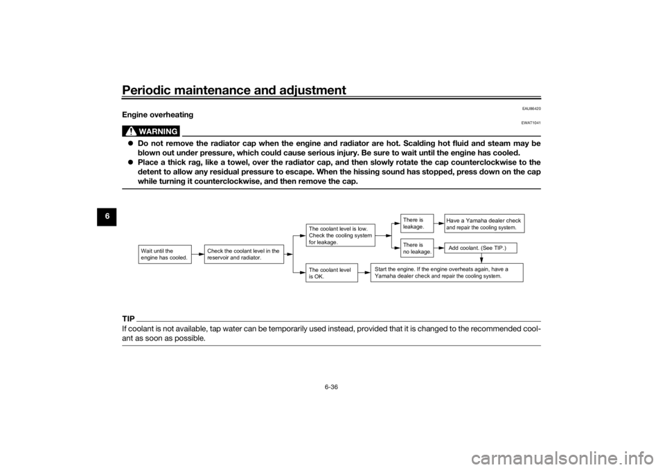
En gine overheatin g
WARNING
EWAT1041
Do not remove the ra diator cap when the en gine an d ra diator are hot. Scal din g hot flui d an d steam may be
b lown out un der pressure, which coul d cause serious injury. Be sure to wait until the en gine has coole d.
Place a thick ra g, like a towel, over the ra diator cap, an d then slowly rotate the cap counterclockwise to the
d etent to allow any resi dual pressure to escape. When the hissin g soun d has stoppe d, press d own on the cap
while turnin g it counterclockwise, an d then remove the cap.TIPIf coolant is not available, tap water can be temporarily used instead, provided that it is changed to the recommended cool-
ant as soon as possible.
Wait until the
engine has cooled.
Check the coolant level in the
reservoir and radiator.
The coolant level
is OK.The coolant level is low.
Check the cooling system
for leakage.
Have a Yamaha dealer checkand repair the cooling system.Add coolant. (See TIP.)
Start the engine. If the engine overheats again,
have a
Yamaha dealer check
and repair the cooling system.
There is
leakage.
There is
no leakage.
UBATE1E0.book Page 36 Thursday, September 2, 2021 10:34 AM
Page 96 of 100

10-1
10
IndexAABS ....................................................... 3-14
ABS warning light ................................... 3-5
Air filter element and check hose,
replacing and cleaning ....................... 6-15
Air temperature display......................... 3-10
Auxiliary DC connector ......................... 3-24BBattery .................................................. 6-29
Brake and clutch levers, checking and lubricating .................................... 6-27
Brake and shift pedals, checking and
lubricating ........................................... 6-26
Brake fluid, changing ............................ 6-23
Brake fluid level, checking .................... 6-21
Brake lever ............................................ 3-14
Brake lever free play, checking............. 6-20
Brake light switches.............................. 6-20
Brake pedal........................................... 3-14
Brightness control mode ...................... 3-11CCables, checking and lubricating ......... 6-25
Canister................................................. 6-10
Care ........................................................ 7-1
Catalytic converter ................................ 3-18
Clock....................................................... 3-7
Clutch lever ........................................... 3-13
Clutch lever free play, adjusting ........... 6-19
Coolant ................................................. 6-13
Coolant temperature display ................ 3-10
Coolant temperature warning light ......... 3-4DData recording, vehicle ........................... 9-2
Diagnostic connector.............................. 9-2 Dimmer switch...................................... 3-12
Display units, switching .......................... 3-6
Drive chain, cleaning and lubricating ... 6-25
Drive chain slack .................................. 6-23
EEco indicator .......................................... 3-7
Engine break-in ...................................... 5-1
Engine idling speed, checking ............. 6-15
Engine oil and oil filter
cartridge ........... 6-10
Engine overheating ............................... 6-36
Engine serial number .............................. 9-1FFront and rear brake pads, checking ... 6-21
Front fork, checking ............................. 6-28
Fuel ....................................................... 3-16
Fuel consumption, tips for reducing ...... 5-4
Fuel meter .............................................. 3-7
Fuel tank cap ........................................ 3-15
Fuel tank overflow hose ....................... 3-18
Fuses, replacing ................................... 6-31HHandlebar switches .............................. 3-11
Hazard switch....................................... 3-12
Helmet holding cable ........................... 3-20
High beam indicator light ....................... 3-3
Horn switch .......................................... 3-12IIdentification numbers ............................ 9-1
Ignition circuit cut-off system ............... 3-25
Immobilizer system ................................ 3-1
Immobilizer system indicator light .......... 3-5
Indicator lights and warning lights ......... 3-3LLicense plate light bulb, replacing........ 6-32 Luggage strap holders ..........................3-23
MMain switch/steering lock .......................3-2
Maintenance and lubrication, periodic....6-5
Maintenance, emission control
system ..................................................6-3
Malfunction indicator light (MIL)..............3-4
Matte color, caution ................................7-1
Model label .............................................9-1
Multi-function display .............................3-8
Multi-function meter unit .........................3-6NNeutral indicator light ..............................3-3OOil pressure warning light .......................3-3PParking ....................................................5-4
Part locations ..........................................2-1
Pass switch ...........................................3-12SSafety information ...................................1-1
Seats .....................................................3-19
Shifting ....................................................5-3
Shift pedal .............................................3-13
Shock absorber assembly, adjusting ....3-21
Sidestand ..............................................3-24
Sidestand, checking and lubricating.....6-27
Spark plugs, checking ............................6-9
Specifications .........................................8-1
Speedometer ..........................................3-6
Starting the engine ..................................5-2
Steering, checking ................................6-29
Stop/Run/Start switch ..........................3-12
Storage ...................................................7-3
UBATE1E0.book Page 1 Thursday, September 2, 2021 10:34 AM