warning light YAMAHA MT-09 2014 User Guide
[x] Cancel search | Manufacturer: YAMAHA, Model Year: 2014, Model line: MT-09, Model: YAMAHA MT-09 2014Pages: 110, PDF Size: 3.21 MB
Page 47 of 110
OPERATION AND IMPORTANT RIDING POINTS
5-1
5
EAU15952
Read the Owner’s Manual carefully to
become familiar with all controls. If
there is a control or function you do not
understand, ask your Yamaha dealer.
WARNING
EWA10272
Failure to familiarize yourself with
the controls can lead to loss of con-
trol, which coul d cause an acci dent
or injury.
EAU48711
TIPThis model is equipped with: a lean angle sensor to stop the en-
gine in case of a turnover. In this
case, the multi-function display in-
dicates error code 30, but this is
not a malfunction. Turn the key to
“OFF” and then to “ON” to clear
the error code. Failing to do so will
prevent the engine from starting
even though the engine will crank
when pushing the start switch.
an engine auto-stop system. The
engine stops automatically if left
idling for 20 minutes. If the engine
stops, simply push the start
switch to restart the engine.
EAU58030
Startin g the en gineIn order for the ignition circuit cut-off
system to enable starting, one of the
following conditions must be met:
The transmission is in the neutral
position.
The transmission is in gear with
the clutch lever pulled and the
sidestand up.
See page 3-26 for more informa-
tion.
1. Turn the key to “ON” and make sure that the start/engine stop
switch is set to “ ”.
The following warning lights and
indicator light should come on for
a few seconds, then go off. Oil level warning light
Coolant temperature warning
light
Engine trouble warning light
Immobilizer system indicator
lightNOTICE
ECA17671
If the a bove warnin g li ghts or ind ica-
tor li ght do not come on initially
when the key is turned to “ON”, or if
U1RCELE0.book Page 1 Monday, May 12, 2014 8:51 AM
Page 48 of 110
OPERATION AND IMPORTANT RIDING POINTS
5-2
5a warnin
g or in dicator li ght remains
on, see pa ge 3-3 for the correspon d-
in g warnin g an d in dicator li ght cir-
cuit check.
For ABS models:The ABS warning light should
come on when the key is turned to
“ON”, and then go off after travel-
ing at a speed of 10 km/h (6 mi/h)
or higher.
NOTICE
ECA17682
If the ABS warnin g lig ht does not
come on an d then g o off as ex-
plaine d a bove, see pa ge 3-3 for the
warnin g lig ht circuit check.2. Shift the transmission into the
neutral position. The neutral indi-
cator light should come on. If not,
ask a Yamaha dealer to check the
electrical circuit.
3. Start the engine by pushing the “ ” side of the start/engine
stop switch.
If the engine fails to start, release
the start/engine stop switch, wait
a few seconds, and then try again.
Each starting attempt should be as short as possible to preserve
the battery. Do not crank the en-
gine more than 10 seconds on any
one attempt.
NOTICE
ECA11043
For maximum en
gine life, never ac-
celerate har d when the en gine is
col d!
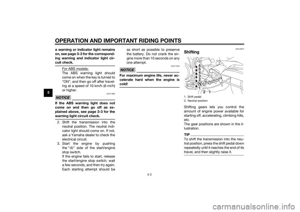
EAU16673
Shiftin gShifting gears lets you control the
amount of engine power available for
starting off, accelerating, climbing hills,
etc.
The gear positions are shown in the il-
lustration.TIPTo shift the transmission into the neu-
tral position, press the shift pedal down
repeatedly until it reaches the end of its
travel, and then slightly raise it.1. Shift pedal
2. Neutral position
1
N
2 3 4 5
6
1
2
U1RCELE0.book Page 2 Monday, May 12, 2014 8:51 AM
Page 49 of 110
OPERATION AND IMPORTANT RIDING POINTS
5-3
5
NOTICE
ECA10261
Even with the transmission in
the neutral position, do not
coast for lon g perio ds of time
with the en gine off, an d d o not
tow the motorcycle for lon g d is-
tances. The transmission is
properly lu bricate d only when
the en gine is runnin g. Ina de-
quate lu brication may damag e
the transmission.
Always use the clutch while
chan gin g g ears to avoi d d am-
a g in g the en gine, transmission,
an d d rive train, which are not
d esi gne d to withstan d the
shock of force d shiftin g.
EAU16682
To start out an d accelerate
1. Pull the clutch lever to disengage the clutch.
2. Shift the transmission into first gear. The neutral indicator light
should go out.
3. Open the throttle gradually, and at the same time, release the clutch
lever slowly. 4. At the recommended shift points
shown in the following table, close
the throttle, and at the same time,
quickly pull the clutch lever in.
5. Shift the transmission into second gear. (Make sure not to shift the
transmission into the neutral posi-
tion.)
6. Open the throttle part way and gradually release the clutch lever.
7. Follow the same procedure when shifting to the next higher gear.
TIPWhen shifting gears in normal operat-
ing conditions, use the recommended
shift points.
EAU58270
To decelerate
1. Release the throttle and apply both the front and the rear brakes
smoothly to slow the motorcycle.
2. At the recommended shift points shown in the following table, shift
to a lower gear.
3. When the motorcycle reaches 25 km/h (16 mi/h), the engine is about
to stall or runs roughly, pull the clutch lever in, use the brakes to
slow the motorcycle, and continue
to downshift as necessary.
4. Once the motorcycle has stopped, the transmission can be
shifted into the neutral position.
The neutral indicator light should
come on and then the clutch lever
can be released.
WARNING
EWA17380
Improper brakin g can cause
loss of control or traction. Al-
ways use both brakes an d apply
them smoothly.
Make sure that the motorcycle
and the en gine have sufficiently
slowe d b efore shiftin g to a low-
er gear. En gag in g a lower gear
when the vehicle or en gine
speed is too hi gh coul d make
the rear wheel lose traction or
the en gine to over-rev. This
coul d cause loss of control, an
acci dent an d injury. It coul d also
cause en gine or d rive train dam-
a g e.
U1RCELE0.book Page 3 Monday, May 12, 2014 8:51 AM
Page 62 of 110
PERIODIC MAINTENANCE AND ADJUSTMENT
6-11
6
TIPBe sure to wipe off spilled oil on any
parts after the engine and exhaust sys-
tem have cooled down.NOTICE
ECA11621
In or der to prevent clutch slip-
pa ge (since the en gine oil also
lu bricates the clutch), do not
mix any chemical additives. Do
not use oils with a d iesel speci-
fication of “CD” or oils of a hi gh-
er quality than specifie d. In
a ddition, do not use oils la beled
“ENERGY CONSERVING II” or
hi gher.
Make sure that no forei gn mate-
rial enters the crankcase.
10. Start the engine, and then let it idle for several minutes while checking
it for oil leakage. If oil is leaking,
immediately turn the engine off
and check for the cause.TIPAfter the engine is started, the engine
oil level warning light should go off if
the oil level is sufficient.NOTICE
ECA10402
If the oil level warnin g lig ht flickers
or remains on even if the oil level is
correct, immed iately turn the en gine
off an d have a Yamaha d ealer check
the vehicle.11. Turn the engine off, wait a few minutes until the oil settles, and
then check the oil level and cor-
rect it if necessary.
EAU20071
CoolantThe coolant level should be checked
before each ride. In addition, the cool-
ant must be changed at the intervals
specified in the periodic maintenance
and lubrication chart.
EAU20093
To check the coolant level1. Place the vehicle on a level sur- face and hold it in an upright posi-
tion.TIPThe coolant level must be
checked on a cold engine since
the level varies with engine tem-
perature.
Make sure that the vehicle is posi-
tioned straight up when checking
the coolant level. A slight tilt to the
side can result in a false reading.2. Check the coolant level in the
coolant reservoir.TIPThe coolant should be between the
minimum and maximum level marks.
Recommen ded en gine oil:
See page 8-1.
Oil quantity: Without oil filter cartridge replace-
ment:2.40 L (2.54 US qt, 2.11 Imp.qt)
With oil filter cartridge replacement:
2.70 L (2.85 US qt, 2.38 Imp.qt)
U1RCELE0.book Page 11 Monday, May 12, 2014 8:51 AM
Page 84 of 110
PERIODIC MAINTENANCE AND ADJUSTMENT
6-33
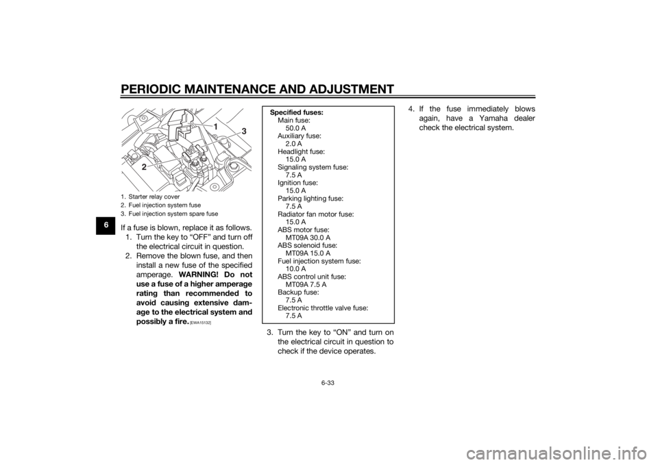
6If a fuse is blown, replace it as follows.
1. Turn the key to “OFF” and turn off the electrical circuit in question.
2. Remove the blown fuse, and then install a new fuse of the specified
amperage. WARNING! Do not
use a fuse of a hi gher ampera ge
ratin g than recommen ded to
avoi d causin g extensive d am-
a g e to the electrical system an d
possi bly a fire.
[EWA15132]
3. Turn the key to “ON” and turn on
the electrical circuit in question to
check if the device operates. 4. If the fuse immediately blows
again, have a Yamaha dealer
check the electrical system.
1. Starter relay cover
2. Fuel injection system fuse
3. Fuel injection system spare fuse
1
2
3
Specifie d fuses:
Main fuse:
50.0 A
Auxiliary fuse:
2.0 A
Headlight fuse: 15.0 A
Signaling system fuse: 7.5 A
Ignition fuse:
15.0 A
Parking lighting fuse: 7.5 A
Radiator fan motor fuse: 15.0 A
ABS motor fuse:
MT09A 30.0 A
ABS solenoid fuse: MT09A 15.0 A
Fuel injection system fuse: 10.0 A
ABS control unit fuse:
MT09A 7.5 A
Backup fuse: 7.5 A
Electronic throttle valve fuse: 7.5 A
U1RCELE0.book Page 33 Monday, May 12, 2014 8:51 AM
Page 99 of 110

MOTORCYCLE CARE AND STORAGE7-3
7
4. To prevent corrosion, it is recom-
mended to apply a corrosion pro-
tection spray on all metal,
including chrome- and nickel-plat-
ed, surfaces.
5. Use spray oil as a universal clean- er to remove any remaining dirt.
6. Touch up minor paint damage caused by stones, etc.
7. Wax all painted surfaces.
8. Let the motorcycle dry completely before storing or covering it.
WARNING
EWA11132
Contaminants on the b rakes or tires
can cause loss of control. Make sure that there is no oil or
wax on the brakes or tires.
If necessary, clean the brake
d iscs an d b rake linin gs with a
re gular brake disc cleaner or
acetone, an d wash the tires with
warm water an d a mil d d eter-
g ent. Before rid ing at hi gher
spee ds, test the motorcycle’s
b rakin g performance an d cor-
nerin g b ehavior.
NOTICE
ECA10801
Apply spray oil an d wax spar-
in gly an d make sure to wipe off
any excess.
Never apply oil or wax to any
rubber an d plastic parts, b ut
treat them with a suita ble care
prod uct.
Avoi d using abrasive polishin g
compoun ds as they will wear
away the paint.TIP Consult a Yamaha dealer for ad-
vice on what products to use.
Washing, rainy weather or humid
climates can cause the headlight
lens to fog. Turning the headlight
on for a short period of time will
help remove the moisture from the
lens.
EAU26183
Stora geShort-term
Always store your motorcycle in a cool,
dry place and, if necessary, protect it
against dust with a porous cover. Be
sure the engine and the exhaust sys-
tem are cool before covering the mo-
torcycle.NOTICE
ECA10811
Storin g the motorcycle in a
poorly ventilated room or cover-
in g it with a tarp, while it is still
wet, will allow water an d humi d-
ity to seep in an d cause rust.
To prevent corrosion, avoi d
d amp cellars, stab les (because
of the presence of ammonia)
an d areas where stron g chemi-
cals are stored .Long-term
Before storing your motorcycle for sev-
eral months: 1. Follow all the instructions in the “Care” section of this chapter.
U1RCELE0.book Page 3 Monday, May 12, 2014 8:51 AM
Page 103 of 110

SPECIFICATIONS
8-3
8
Electrical system:Ignition system:TCI
Charging system:
AC magnetoBattery:Model:YTZ10S
Voltage, capacity:
12 V, 8.6 AhHea dlig ht:Bulb type:
Halogen bulbBul b volta ge, watta ge × quantity:Headlight:
12 V, 60.0 W/55.0 W × 1
Tail/brake light: LED
Front turn signal light:
12 V, 10.0 W × 2
Rear turn signal light: 12 V, 10.0 W × 2
Auxiliary light: 12 V, 5.0 W × 2
License plate light:
12 V, 5.0 W × 1
Meter lighting: LED
Neutral indicator light: LED
High beam indicator light:
LED
Oil level warning light: LED Turn signal indicator light:
LED
Coolant temperature warning light: LED
Engine trouble warning light:
LED
ABS warning light: MT09A LED
Immobilizer system indicator light: LED
Fuses:Main fuse:50.0 A
Auxiliary fuse: 2.0 A
Headlight fuse:
15.0 A
Signaling system fuse: 7.5 A
Ignition fuse: 15.0 A
Parking lighting fuse:
7.5 A
Radiator fan motor fuse: 15.0 A
Fuel injection system fuse: 10.0 A
ABS control unit fuse:
MT09A 7.5 A
ABS motor fuse: MT09A 30.0 A
ABS solenoid fuse: MT09A 15.0 A Backup fuse:
7.5 A
Electronic throttle valve fuse: 7.5 A
U1RCELE0.book Page 3 Monday, May 12, 2014 8:51 AM
Page 106 of 110

10-1
10
INDEXAABS (for ABS models) ........................... 3-17
ABS warning light (for ABS models) ....... 3-5
Air filter element .................................... 6-14
Auxiliary DC connector ......................... 3-28
Auxiliary light bulb, replacing ................ 6-38BBattery .................................................. 6-29
Brake and clutch levers, checking and lubricating ........................................... 6-26
Brake and shift pedals, checking and lubricating ........................................... 6-26
Brake fluid, changing ............................ 6-22
Brake fluid level, checking .................... 6-21
Brake lever ............................................ 3-16
Brake lever free play, checking............. 6-19
Brake light switches.............................. 6-20
Brake pedal........................................... 3-17CCables, checking and lubricating ......... 6-25
Care ........................................................ 7-1
Catalytic converter ................................ 3-20
Clutch lever ........................................... 3-16
Clutch lever free play, adjusting ........... 6-18
Coolant ................................................. 6-11
Coolant temperature warning light ......... 3-4DDimmer switch ...................................... 3-14
D-mode (drive mode) ............................ 3-13
Drive chain, cleaning and lubricating .... 6-24
Drive chain slack................................... 6-23EEngine break-in....................................... 5-4
Engine idling speed, checking .............. 6-14 Engine oil and oil filter
cartridge ............. 6-9
Engine serial number .............................. 9-1
Engine trouble warning light ................... 3-4
FFront and rear brake pads, checking ... 6-20
Front fork, adjusting ............................. 3-22
Front fork, checking ............................. 6-28
Fuel ....................................................... 3-19
Fuel consumption, tips for reducing ...... 5-4
Fuel tank breather hose and overflow
hose ................................................... 3-20
Fuel tank cap ........................................ 3-18
Fuses, replacing ................................... 6-31HHandlebar switches .............................. 3-14
Hazard switch....................................... 3-15
Headlight bulb, replacing ..................... 6-34
High beam indicator light ....................... 3-4
Horn switch .......................................... 3-15IIdentification numbers ............................ 9-1
Ignition circuit cut-off system ............... 3-26
Immobilizer system ................................ 3-1
Immobilizer system indicator light .......... 3-5
Indicator lights and warning lights ......... 3-3LLicense plate light bulb, replacing........ 6-37
Luggage strap holders ......................... 3-25MMain switch/steering lock....................... 3-2
Maintenance and lubrication, periodic ... 6-4
Maintenance, emission control system.................................................. 6-3
Matte color, caution ............................... 7-1 Model label .............................................9-1
Multi-function meter unit .........................3-6
NNeutral indicator light ..............................3-4OOil level warning light ..............................3-4PParking ....................................................5-5
Part locations ..........................................2-1
Pass switch ...........................................3-14SSafety information ...................................1-1
Seat .......................................................3-21
Shifting ....................................................5-2
Shift pedal .............................................3-16
Shock absorber assembly, adjusting ....3-24
Sidestand ..............................................3-26
Sidestand, checking and lubricating.....6-27
Spark plugs, checking ............................6-8
Specifications .........................................8-1
Start/Engine stop switch .......................3-15
Starting the engine ..................................5-1
Steering, checking ................................6-28
Storage ...................................................7-3
Storage compartment ...........................3-22
Supporting the motorcycle ...................6-39
Swingarm pivots, lubricating ................6-27TTail/brake light ......................................6-36
Throttle grip and cable, checking and
lubricating ...........................................6-25
Throttle grip free play, checking ...........6-15
Tires ......................................................6-15
Tool kit ....................................................6-2
U1RCELE0.book Page 1 Monday, May 12, 2014 8:51 AM