clock YAMAHA MT-09 2016 Owners Manual
[x] Cancel search | Manufacturer: YAMAHA, Model Year: 2016, Model line: MT-09, Model: YAMAHA MT-09 2016Pages: 114, PDF Size: 4.24 MB
Page 22 of 114

Instrument and control functions
3-7
1
23
4
5
6
7
8
9
10
11
12
EAU73263
Multi-function meter unit
MT09 MT09A
WARNING
EWA12423
Be sure to stop the vehicle before
making any setting changes to the
multi-function meter unit. Changing
settings while riding can distract the
operator and increase the risk of anaccident.
1. “SELECT” button
2. “RESET” button
2
1
1. Transmission gear display
2. Tachometer
3. Drive mode display
4. Fuel meter
5. Eco indicator “ECO”
6. Multi-function display
7. Clock
8. Speedometer1
2
3
4
5
6
7
8
1. Transmission gear display
2. Tachometer
3. Eco indicator “ECO”
4. TCS display
5. Drive mode display
6. Fuel meter
7. Multi-function display
8. Clock
9. Speedometer1
2
4
3
5
6
7
8
9
B87-9-E0_1.book 7 ページ 2015年12月16日 水曜日 午前10時21分
Page 23 of 114

Instrument and control functions
3-8
1
234
5
6
7
8
9
10
11
12
The multi-function meter unit is
equipped with the following:
a speedometer
a tachometer
a clock
a fuel meter
an eco indicator
a transmission gear display
a drive mode display
a TCS display (for equipped mod-
els)
a multi-function display
TIP
Except when switching to the
brightness control mode or to dis-
play the clock, turn the key to “ON”
before using the “SELECT” and
“RESET” buttons to adjust the
multi-function meter.
For the UK: To switch the speed-
ometer and multi-function displays
between kilometers and miles,
press the “SELECT” button for onesecond.
Speedometer
The speedometer shows the vehicle’s
traveling speed.
Tachometer
The tachometer allows the rider to
monitor the engine speed and keep it
within the ideal power range.
When the key is turned to “ON”, the ta-
chometer will sweep across the r/min
range and then return to zero r/min in
order to test the electrical circuit.
NOTICE
ECA10032
Do not operate the engine in the ta-
chometer red zone.Red zone: 11250 r/min and above
Clock
The clock uses a 12-hour time system.
When the key is not in the “ON” posi-
tion, the clock can be viewed for 10
1. Speedometer
1. Tachometer
2. Tachometer red zone
1
2
1
1. Clock
1
B87-9-E0_1.book 8 ページ 2015年12月16日 水曜日 午前10時21分
Page 24 of 114

Instrument and control functions
3-9
1
23
4
5
6
7
8
9
10
11
12 seconds by pushing the “SELECT” but-
ton.
To set the clock
1. Turn the key to “ON”.
2. Push the “SELECT” button and
“RESET” button together for two
seconds.
3. When the hour digits start flashing, push the “RESET” button to set the
hours.
4. Push the “SELECT” button, and the minute digits will start flashing.
5. Push the “RESET” button to set the minutes.
6. Push the “SELECT” button and then release it to start the clock. Fuel meter
The fuel meter indicates the amount of
fuel in the fuel tank. The display seg-
ments of the fuel meter disappear to-
wards “E” (empty) as the fuel level
decreases. When the last segment
starts flashing (“ ” will also flash for
MT09), refuel as soon as possible.
TIPIf a problem is detected in the electrical
ciruit, the fuel level segments and “ ”
will flash repeatedly. If this occurs, havea Yamaha dealer check vehicle. Eco indicator
MT09
MT09A
This indicator comes on when the vehi-
cle is being operated in an environmen-
tally friendly, fuel-efficient manner. The1. Fuel meter
1
1. Eco indicator “ECO”
1. Eco indicator “ECO”
1
1
B87-9-E0_1.book 9 ページ 2015年12月16日 水曜日 午前10時21分
Page 37 of 114

Instrument and control functions
3-22
1
234
5
6
7
8
9
10
11
12
turned to “ON” (such as when per-
forming maintenance).
If the traction control system is dis-
abled, both the “ ” indicator light and
the “ ” warning light will come on.
Should this occur, try resetting the sys-
tem as follows. 1. Stop the vehicle and turn the key to “OFF”.
2. Wait a few seconds and then turn key back “ON”.
3. The “ ” indicator light should turn off and the system be enabled.
4. The “ ” warning light should go off after the vehicle reaches a trav-
eling speed of 20 km/h (12 mi/h).
TIPIf the “ ” indicator light or the “ ”
warning light remains on after resetting,
the vehicle may still be ridden; howev-
er, have a Yamaha dealer check thevehicle as soon as possible.
EAU13075
Fuel tank capTo open the fuel tank cap
Open the fuel tank cap lock cover, in-
sert the key into the lock, and then turn
it 1/4 turn clockwise. The lock will be re-
leased and the fuel tank cap can be
opened.
To close the fuel tank cap1. Push the fuel tank cap into position with the key inserted in the lock.
2. Turn the key counterclockwise to the original position, remove it, and
then close the lock cover.
TIPThe fuel tank cap cannot be closed un-
less the key is in the lock. In addition,
the key cannot be removed if the cap isnot properly closed and locked.
WARNING
EWA11092
Make sure that the fuel tank cap is
properly closed after filling fuel.Leaking fuel is a fire hazard.
1. Unlock.
2. Fuel tank cap lock cover
2
1
B87-9-E0_1.book 22 ページ 2015年12月16日 水曜日 午前10時21分
Page 40 of 114

Instrument and control functions
3-25
1
23
4
5
6
7
8
9
10
11
12 pairable damage to the catalytic
converter.
EAU57991
SeatTo remove the seat
1. Open the seat lock cover, insert the key into the seat lock, and then
turn the key counterclockwise.
2. While holding the key in that posi- tion, lift the rear of the seat up, and
then pull the seat off.
To install the seat 1. Insert the projections into the seat holders as shown. 2. Push the rear of the seat down to
lock it in place.
3. Remove the key.
TIPMake sure that the seat is properly se-cured before riding.
1. Seat lock
2. Seat lock cover
3. Unlock.1
32
1. Projection
2. Seat holder
1
2
21
B87-9-E0_1.book 25 ページ 2015年12月16日 水曜日 午前10時21分
Page 87 of 114

Periodic maintenance and adjustment6-32
1
2
3
4
567
8
9
10
11
12
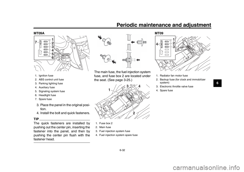
MT09A
3. Place the panel in the original posi- tion.
4. Install the bolt and quick fasteners.
TIPThe quick fasteners are installed by
pushing out the center pin, inserting the
fastener into the panel, and then by
pushing the center pin flush with thefastener head. The main fuse, the fuel injection system
fuse, and fuse box 2 are located under
the seat. (See page 3-25.)
MT091. Ignition fuse
2. ABS control unit fuse
3. Parking lighting fuse
4. Auxiliary fuse
5. Signaling system fuse
6. Headlight fuse
7. Spare fuse
123
7
456
1. Fuse box 2
2. Main fuse
3. Fuel injection system fuse
4. Fuel injection system spare fuse
2
3
4
1
1. Radiator fan motor fuse
2. Backup fuse (for clock and immobilizer
system)
3. Electronic throttle valve fuse
4. Spare fuse
123
4
B87-9-E0_1.book 32 ページ 2015年12月16日 水曜日 午前10時21分
Page 88 of 114

Periodic maintenance and adjustment
6-33
1
2
3
4
56
7
8
9
10
11
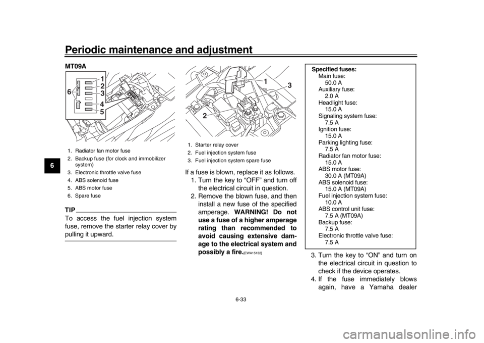
12 MT09A
TIPTo access the fuel injection system
fuse, remove the starter relay cover bypulling it upward.
If a fuse is blown, replace it as follows.
1. Turn the key to “OFF” and turn off the electrical circuit in question.
2. Remove the blown fuse, and then install a new fuse of the specified
amperage. WARNING! Do not
use a fuse of a higher amperage
rating than recommended to
avoid causing extensive dam-
age to the electrical system and
possibly a fire.
[EWA15132]
3. Turn the key to “ON” and turn on the electrical circuit in question to
check if the device operates.
4. If the fuse immediately blows again, have a Yamaha dealer
1. Radiator fan motor fuse
2. Backup fuse (for clock and immobilizer system)
3. Electronic throttle valve fuse
4. ABS solenoid fuse
5. ABS motor fuse
6. Spare fuse
123
6
45
1. Starter relay cover
2. Fuel injection system fuse
3. Fuel injection system spare fuse
1
2
3
Specified fuses: Main fuse:50.0 A
Auxiliary fuse:
2.0 A
Headlight fuse: 15.0 A
Signaling system fuse: 7.5 A
Ignition fuse:
15.0 A
Parking lighting fuse: 7.5 A
Radiator fan motor fuse: 15.0 A
ABS motor fuse:
30.0 A (MT09A)
ABS solenoid fuse: 15.0 A (MT09A)
Fuel injection system fuse: 10.0 A
ABS control unit fuse:
7.5 A (MT09A)
Backup fuse: 7.5 A
Electronic throttle valve fuse: 7.5 A
B87-9-E0_1.book 33 ページ 2015年12月16日 水曜日 午前10時21分
Page 92 of 114

Periodic maintenance and adjustment
6-37
1
2
3
4
56
7
8
9
10
11
12 2. Remove the auxiliary light bulb
socket (together with the bulb) by
turning it counterclockwise.
3. Remove the burnt-out bulb by pull- ing it out. 4. Insert a new bulb into the socket.
5. Install the socket (together with the
bulb) by turning it clockwise.
6. Place the headlight unit side cov- ers in their original position, and
then install the bolts.
EAU70540
Brake/tail lightThis model is equipped with an
LED-type brake/tail light.
If the brake/tail light does not come on,
have a Yamaha dealer check it.
1. Bolt
2. Headlight unit side cover
1. Auxiliary light bulb socket1
1
2
2
1
1. Auxiliary light bulb1
B87-9-E0_1.book 37 ページ 2015年12月16日 水曜日 午前10時21分
Page 93 of 114

Periodic maintenance and adjustment6-38
1
2
3
4
567
8
9
10
11
12
EAU24205
Replacing a turn signal light
bulb1. Remove the turn signal light lens by removing the screw.
2. Remove the burnt-out bulb by pushing it in and turning it counter-
clockwise. 3. Insert a new bulb into the socket,
push it in, and then turn it clock-
wise until it stops.
4. Install the lens by installing the screw. NOTICE: Do not over-
tighten the screw, otherwise the
lens may break.
[ECA11192] EAU58010
Replacing the license plate
light bulb1. Remove the license plate light unit
by removing the nuts and collars,
and then remove the license plate
light bulb socket (together with the
bulb) by pulling it out.
2. Remove the burnt-out bulb by pull- ing it out.
1. Turn signal light lens
2. Screw
1
2
1. Turn signal light bulb
1
1. License plate light unit
2. Collar
3. Nut
4. License plate light bulb socket
1
22
4
3
3
B87-9-E0_1.book 38 ページ 2015年12月16日 水曜日 午前10時21分
Page 100 of 114

Periodic maintenance and adjustment
6-45
1
2
3
4
56
7
8
9
10
11
12 Engine overheating
WARNING
EWA10401
Do not remove the radiator cap when the engine and radiator are hot. Scalding hot fluid and steam may be
blown out under pressure, which could cause serious injury. Be sure to wait until the engine has cooled.
After removing the radiator cap retaining bolt, place a thick rag, like a towel, over the radiator cap, and then
slowly rotate the cap counterclockwise to the detent to allow any residual pressure to escape. When the hissingsound has stopped, press down on the cap while turning it counterclockwise, and then remove the cap.
TIPIf coolant is not available, tap water can be temporarily us
ed instead, provided that it is changed to the recommended coolantas soon as possible.
Wait until the
engine has cooled.
Check the coolant level in the
reservoir and radiator.
The coolant level
is OK.The coolant level is low.
Check the cooling system
for leakage.
Have a Yamaha dealer checkand repair the cooling system.Add coolant. (See TIP.)
Start the engine. If the engine overheats again,
have a
Yamaha dealer check
and repair the cooling system.
There is
leakage.
There is
no leakage.
B87-9-E0_1.book 45 ページ 2015年12月16日 水曜日 午前10時21分