lock YAMAHA MT-09 2019 User Guide
[x] Cancel search | Manufacturer: YAMAHA, Model Year: 2019, Model line: MT-09, Model: YAMAHA MT-09 2019Pages: 104, PDF Size: 7.14 MB
Page 35 of 104
Instrument and control functions
4-17
1
2
345
6
7
8
9
10
11
12
less the key is in the lock. In addition,
the key cannot be removed if the cap is
not properly closed and locked.
WARNING
EWA11092
Make sure that the fuel tank cap is
properly closed after filling fuel.Leaking fuel is a fire hazard.
EAU13222
FuelMake sure there is sufficient gasoline in
the tank.
WARNING
EWA10882
Gasoline and gasoline vapors are
extremely flammable. To avoid fires
and explosions and to reduce the
risk of injury when refueling, followthese instructions.
1. Before refueling, turn off the en- gine and be sure that no one is sit-
ting on the vehicle. Never refuel
while smoking, or while in the vi-
cinity of sparks, open flames, or
other sources of ignition such as
the pilot lights of water heaters and
clothes dryers.
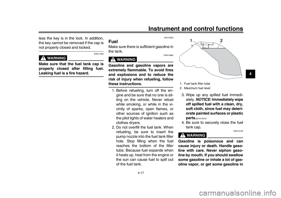
2. Do not overfill the fuel tank. When refueling, be sure to insert the
pump nozzle into the fuel tank filler
hole. Stop filling when the fuel
reaches the bottom of the filler
tube. Because fuel expands when
it heats up, heat from the engine or
the sun can cause fuel to spill out
of the fuel tank. 3. Wipe up any spilled fuel immedi-
ately. NOTICE: Immediately wipe
off spilled fuel with a clean, dry,
soft cloth, since fuel may deteri-
orate painted surfaces or plastic
parts.
[ECA10072]
4. Be sure to securely close the fuel tank cap.
WARNING
EWA15152
Gasoline is poisonous and can
cause injury or death. Handle gaso-
line with care. Never siphon gaso-
line by mouth. If you should swallow
some gasoline or inhale a lot of gas-
oline vapor, or get some gasoline in1. Fuel tank filler tube
2. Maximum fuel level
1
2
BS2-9-E2.book 17 ページ 2018年8月10日 金曜日 午前9時36分
Page 37 of 104

Instrument and control functions
4-19
1
2
345
6
7
8
9
10
11
12
EAU72972
Fuel tank overflow hoseBefore operating the vehicle:
Check the overflow hose connec-
tion and for damage.
Confirm the overflow hose is not
blocked and is routed through the
clamp.
TIPSee page 7-11 for canister information.
EAU13434
Catalytic converterThis model is equipped with a catalytic
converter in the exhaust system.
WARNING
EWA10863
The exhaust system is hot after op-
eration. To prevent a fire hazard or
burns:
Do not park the vehicle near
possible fire hazards such as
grass or other materials that
easily burn.
Park the vehicle in a place
where pedestrians or children
are not likely to touch the hot
exhaust system.
Make sure that the exhaust sys-
tem has cooled down before do-
ing any maintenance work.
Do not allow the engine to idle
more than a few minutes. Long
idling can cause a build-up ofheat.
NOTICE
ECA10702
Use only unleaded gasoline. The use
of leaded gasoline will cause unre- pairable damage to the catalytic
converter.
1. Fuel tank overflow hose
2. Clamp
21
BS2-9-E2.book 19 ページ 2018年8月10日 金曜日 午前9時36分
Page 38 of 104
Instrument and control functions
4-20
1
2
34
5
6
7
8
9
10
11
12
EAU57991
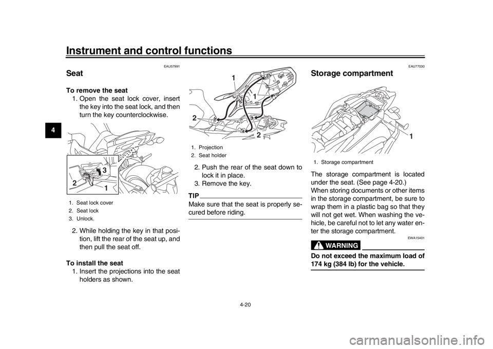
SeatTo remove the seat 1. Open the seat lock cover, insert the key into the seat lock, and then
turn the key counterclockwise.
2. While holding the key in that posi- tion, lift the rear of the seat up, and
then pull the seat off.
To install the seat 1. Insert the projections into the seat holders as shown. 2. Push the rear of the seat down to
lock it in place.
3. Remove the key.
TIPMake sure that the seat is properly se-cured before riding.
EAU77030
Storage compartmentThe storage compartment is located
under the seat. (See page 4-20.)
When storing documents or other items
in the storage compartment, be sure to
wrap them in a plastic bag so that they
will not get wet. When washing the ve-
hicle, be careful not to let any water en-
ter the storage compartment.
WARNING
EWA15401
Do not exceed the maximum load of174 kg (384 lb) for the vehicle.
1. Seat lock cover
2. Seat lock
3. Unlock.2
31
1. Projection
2. Seat holder
1
2
21
1. Storage compartment
1
BS2-9-E2.book 20 ページ 2018年8月10日 金曜日 午前9時36分
Page 63 of 104
Periodic maintenance and adjustment7-11
1
2
3
4
5
678
9
10
11
12
installing a spark plug, a good estimate
of the correct torque is 1/4–1/2 turn
past finger tight. However, the spark
plug should be tightened to the speci-
fied torque as soon as possible.NOTICE
ECA10841
Do not use any tools to remove or in-
stall the spark plug cap, otherwise
the ignition coil coupler may get
damaged. The spark plug cap may
be difficult to remove because the
rubber seal on the end of the cap fits
tightly. To remove the spark plug
cap, simply twist it back and forth
while pulling it out; to install it, twistit back and forth while pushing it in.
EAU36112
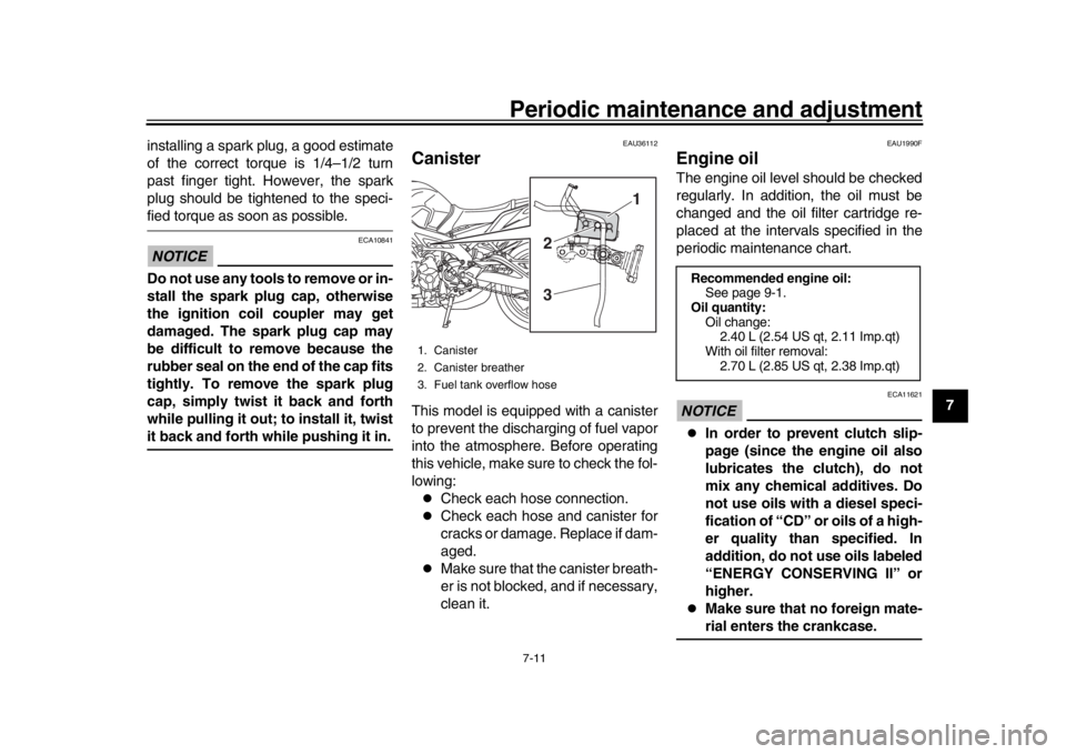
CanisterThis model is equipped with a canister
to prevent the discharging of fuel vapor
into the atmosphere. Before operating
this vehicle, make sure to check the fol-
lowing:
Check each hose connection.
Check each hose and canister for
cracks or damage. Replace if dam-
aged.
Make sure that the canister breath-
er is not blocked, and if necessary,
clean it.
EAU1990F
Engine oilThe engine oil level should be checked
regularly. In addition, the oil must be
changed and the oil filter cartridge re-
placed at the intervals specified in the
periodic maintenance chart.NOTICE
ECA11621
In order to prevent clutch slip-
page (since the engine oil also
lubricates the clutch), do not
mix any chemical additives. Do
not use oils with a diesel speci-
fication of “CD” or oils of a high-
er quality than specified. In
addition, do not use oils labeled
“ENERGY CONSERVING II” or
higher.
Make sure that no foreign mate-rial enters the crankcase.
1. Canister
2. Canister breather
3. Fuel tank overflow hose
1
2
3
Recommended engine oil: See page 9-1.
Oil quantity: Oil change:2.40 L (2.54 US qt, 2.11 Imp.qt)
With oil filter removal: 2.70 L (2.85 US qt, 2.38 Imp.qt)
BS2-9-E2.book 11 ページ 2018年8月10日 金曜日 午前9時36分
Page 73 of 104
Periodic maintenance and adjustment7-21
1
2
3
4
5
678
9
10
11
12
sult in loss of control and an acci-
dent.
EAU36505
Brake light switchesThe brake light should come on just be-
fore braking takes effect. The brake
light is activated by switches connected
to the brake lever and brake pedal.
Since the brake light switches are com-
ponents of the anti-lock brake system,
they should only be serviced by a
Yamaha dealer.
EAU22393
Checking the front and rear
brake padsThe front and rear brake pads must be
checked for wear at the intervals spec-
ified in the periodic maintenance and
lubrication chart.
EAU36891
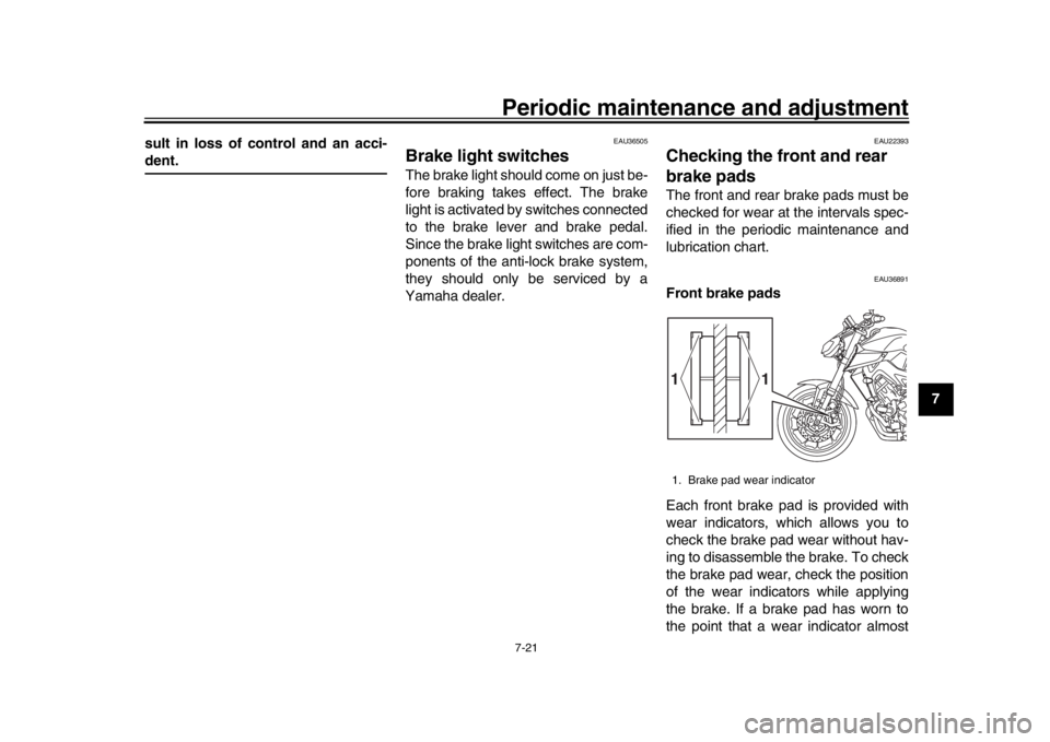
Front brake pads
Each front brake pad is provided with
wear indicators, which allows you to
check the brake pad wear without hav-
ing to disassemble the brake. To check
the brake pad wear, check the position
of the wear indicators while applying
the brake. If a brake pad has worn to
the point that a wear indicator almost1. Brake pad wear indicator
1
1
BS2-9-E2.book 21 ページ 2018年8月10日 金曜日 午前9時36分
Page 75 of 104
Periodic maintenance and adjustment7-23
1
2
3
4
5
678
9
10
11
12
may deteriorate, causing leak-
age.
Refill with the same type of
brake fluid. Adding a brake fluid
other than DOT 4 may result in a
harmful chemical reaction.
Be careful that water or dust
does not enter the brake fluid
reservoir when refilling. Water
will significantly lower the boil-
ing point of the fluid and may re-
sult in vapor lock, and dirt may
clog the ABS hydraulic unitvalves.
NOTICE
ECA17641
Brake fluid may damage painted sur-
faces or plastic parts. Always cleanup spilled fluid immediately.
As the brake pads wear, it is normal for
the brake fluid level to gradually go
down. A low brake fluid level may indi-
cate worn brake pads and/or brake sys-
tem leakage; therefore, be sure to
check the brake pads for wear and the
brake system for leakage. If the brake
fluid level goes down suddenly, have a
Yamaha dealer check the cause before further riding.
EAU22734
Changing the brake fluidHave a Yamaha dealer change the
brake fluid every 2 years. In addition,
have the seals of the master cylinders
and brake calipers, as well as the brake
hoses replaced at the intervals listed
below or sooner if they are damaged or
leaking.
Brake seals: every 2 years
Brake hoses: every 4 years
BS2-9-E2.book 23 ページ 2018年8月10日 金曜日 午前9時36分
Page 76 of 104
Periodic maintenance and adjustment
7-24
1
2
3
4
5
67
8
9
10
11
12
EAU22762
Drive chain slackThe drive chain slack should be
checked before each ride and adjusted
if necessary.
EAU2277G
To check the drive chain slack 1. Place the motorcycle on the sides- tand.TIPWhen checking and adjusting the drive
chain slack, there should be no weighton the motorcycle.
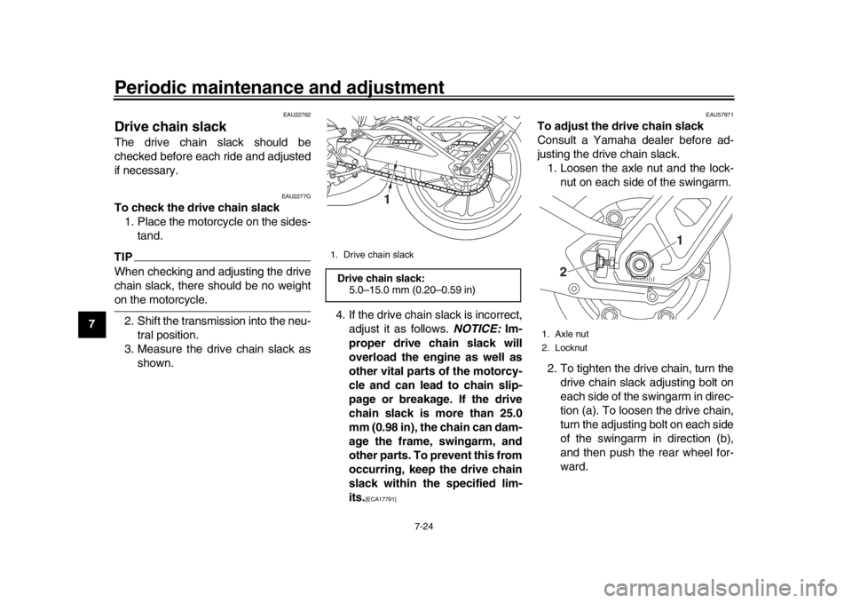
2. Shift the transmission into the neu- tral position.
3. Measure the drive chain slack as shown. 4. If the drive chain slack is incorrect,
adjust it as follows. NOTICE: Im-
proper drive chain slack will
overload the engine as well as
other vital parts of the motorcy-
cle and can lead to chain slip-
page or breakage. If the drive
chain slack is more than 25.0
mm (0.98 in), the chain can dam-
age the frame, swingarm, and
other parts. To prevent this from
occurring, keep the drive chain
slack within the specified lim-
its.
[ECA17791] EAU57971
To adjust the drive chain slack
Consult a Yamaha dealer before ad-
justing the drive chain slack.
1. Loosen the axle nut and the lock- nut on each side of the swingarm.
2. To tighten the drive chain, turn the drive chain slack adjusting bolt on
each side of the swingarm in direc-
tion (a). To loosen the drive chain,
turn the adjusting bolt on each side
of the swingarm in direction (b),
and then push the rear wheel for-
ward.
1. Drive chain slackDrive chain slack:5.0–15.0 mm (0.20–0.59 in)
1
1. Axle nut
2. Locknut
1
2
BS2-9-E2.book 24 ページ 2018年8月10日 金曜日 午前9時36分
Page 77 of 104

Periodic maintenance and adjustment7-25
1
2
3
4
5
678
9
10
11
12
TIPUsing the alignment marks and notch
on each side of the swingarm, make
sure that both drive chain pullers are in
the same position for proper wheelalignment. 3. Tighten the axle nut, then the lock-
nuts to their specified torques.
4. Make sure that the drive chain pull- ers are in the same position, the
drive chain slack is correct, and
the drive chain moves smoothly.
EAU23026
Cleaning and l ubricating the
drive chainThe drive chain must be cleaned and
lubricated at the intervals specified in
the periodic maintenance and lubrica-
tion chart, otherwise it will quickly wear
out, especially when riding in dusty or
wet areas. Service the drive chain as
follows.NOTICE
ECA10584
The drive chain must be lubricated
after washing the motorcycle, ridingin the rain or riding in wet areas.
1. Clean the drive chain with kero- sene and a small soft brush.
NOTICE: To prevent damaging
the O-rings, do not clean the
drive chain with steam cleaners,
high-pressure washers or inap-
propriate solvents.
[ECA11122]
2. Wipe the drive chain dry.
3. Thoroughly lubricate the drive chain with a special O-ring chain
lubricant. NOTICE: Do not use
engine oil or any other lubri-
cants for the drive chain, as they
1. Drive chain slack adjusting bolt
1
(a) (b)
1. Notch
2. Alignment marks
3. Drive chain puller Tightening torques:
Axle nut:150 N·m (15 kgf·m, 111 lb·ft)
Locknut:
16 N·m (1.6 kgf·m, 12 lb·ft)
1
2 3
BS2-9-E2.book 25 ページ 2018年8月10日 金曜日 午前9時36分
Page 86 of 104

Periodic maintenance and adjustment
7-34
1
2
3
4
5
67
8
9
10
11
12
EAU76271
Vehicle lightsExcept for the turn signal lights, this
model is equipped with full-LED light-
ing. If a light does not come on, check
the fuses and then have a Yamaha
dealer check the vehicle.
If a turn signal light does not come,
check and replace the bulb. (See
page 7-34.)TIPWhen the dimmer switch is set to high
beam or the passing switch is pushed,all four headlights come on.
NOTICE
ECA16581
Do not affix any type of tinted film orstickers to the headlight lens.
EAU24205
Replacing a turn signal light
bulb1. Remove the turn signal light lens by removing the screw.
2. Remove the burnt-out bulb by pushing it in and turning it counter-
clockwise.
1. Headlight (low beam)
2. Headlight (high beam)
3. Auxiliary light
12
3
1. Turn signal light lens
2. Screw
1
2
BS2-9-E2.book 34 ページ 2018年8月10日 金曜日 午前9時36分
Page 87 of 104
Periodic maintenance and adjustment7-35
1
2
3
4
5
678
9
10
11
12
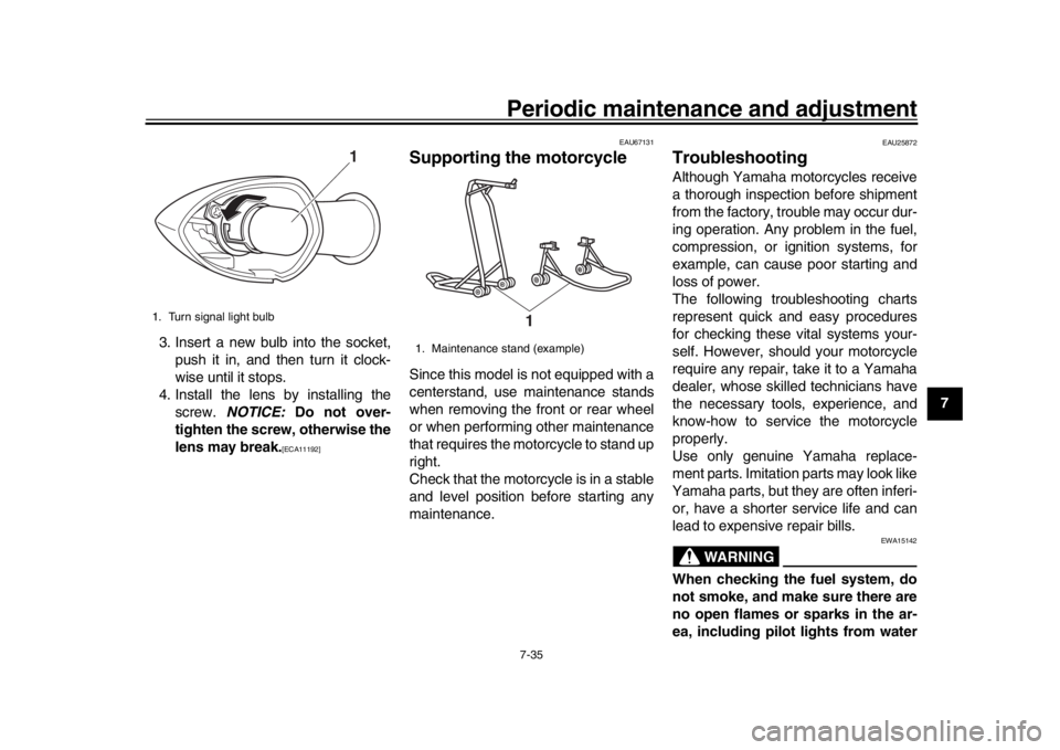
3. Insert a new bulb into the socket,
push it in, and then turn it clock-
wise until it stops.
4. Install the lens by installing the screw. NOTICE: Do not over-
tighten the screw, otherwise the
lens may break.
[ECA11192] EAU67131
Supporting the motorcycleSince this model is not equipped with a
centerstand, use maintenance stands
when removing the front or rear wheel
or when performing other maintenance
that requires the motorcycle to stand up
right.
Check that the motorcycle is in a stable
and level position before starting any
maintenance.
EAU25872
TroubleshootingAlthough Yamaha motorcycles receive
a thorough inspection before shipment
from the factory, trouble may occur dur-
ing operation. Any problem in the fuel,
compression, or ignition systems, for
example, can cause poor starting and
loss of power.
The following troubleshooting charts
represent quick and easy procedures
for checking these vital systems your-
self. However, should your motorcycle
require any repair, take it to a Yamaha
dealer, whose skilled technicians have
the necessary tools, experience, and
know-how to service the motorcycle
properly.
Use only genuine Yamaha replace-
ment parts. Imitation parts may look like
Yamaha parts, but they are often inferi-
or, have a shorter service life and can
lead to expensive repair bills.
WARNING
EWA15142
When checking the fuel system, do
not smoke, and make sure there are
no open flames or sparks in the ar-
ea, including pilot lights from water
1. Turn signal light bulb
1
1. Maintenance stand (example)
1
BS2-9-E2.book 35 ページ 2018年8月10日 金曜日 午前9時36分