warning YAMAHA MT-09 2019 User Guide
[x] Cancel search | Manufacturer: YAMAHA, Model Year: 2019, Model line: MT-09, Model: YAMAHA MT-09 2019Pages: 104, PDF Size: 7.14 MB
Page 26 of 104

Instrument and control functions
4-8
1
2
34
5
6
7
8
9
10
11
12
WARNING
EWA12423
Be sure to stop the vehicle before
making any setting changes to the
multi-function meter unit. Changing
settings while riding can distract the
operator and increase the risk of anaccident.
The multi-function meter unit is equipped with the following:
a speedometer
a tachometer
a clock
a fuel meter
an eco indicator
a transmission gear display
a drive mode display
a TCS display
a multi-function display
TIPThe multi-function meter unit can be
switched between kilometers and
miles. Set the multi-function display to
the odometer or a tripmeter mode, and
then press the “SELECT” button forone second.
Speedometer
The speedometer shows the vehicle’s
traveling speed.
Tachometer
1. Transmission gear display
2. Tachometer
3. Eco indicator “ECO”
4. TCS display
5. Drive mode display
6. Fuel meter
7. Multi-function display
8. Clock
9. Speedometer1
2
4
3
5
6
7
8
9
1. Speedometer
1. Tachometer
2. Tachometer red zone
1
2
1
BS2-9-E2.book 8 ページ 2018年8月10日 金曜日 午前9時36分
Page 33 of 104
Instrument and control functions
4-15
1
2
345
6
7
8
9
10
11
12
the brake lever.
EAU12944
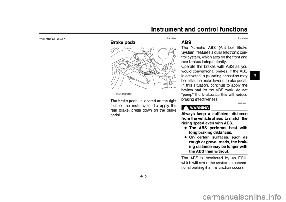
Brake pedalThe brake pedal is located on the right
side of the motorcycle. To apply the
rear brake, press down on the brake
pedal.
EAU63040
ABSThe Yamaha ABS (Anti-lock Brake
System) features a dual electronic con-
trol system, which acts on the front and
rear brakes independently.
Operate the brakes with ABS as you
would conventional brakes. If the ABS
is activated, a pulsating sensation may
be felt at the brake lever or brake pedal.
In this situation, continue to apply the
brakes and let the ABS work; do not
“pump” the brakes as this will reduce
braking effectiveness.
WARNING
EWA16051
Always keep a sufficient distance
from the vehicle ahead to match the
riding speed even with ABS.
The ABS performs best with
long braking distances.
On certain surfaces, such as
rough or gravel roads, the brak-
ing distance may be longer withthe ABS than without.
The ABS is monitored by an ECU,
which will revert the system to conven-
tional braking if a malfunction occurs.
1. Brake pedal
1
BS2-9-E2.book 15 ページ 2018年8月10日 金曜日 午前9時36分
Page 35 of 104
Instrument and control functions
4-17
1
2
345
6
7
8
9
10
11
12
less the key is in the lock. In addition,
the key cannot be removed if the cap is
not properly closed and locked.
WARNING
EWA11092
Make sure that the fuel tank cap is
properly closed after filling fuel.Leaking fuel is a fire hazard.
EAU13222
FuelMake sure there is sufficient gasoline in
the tank.
WARNING
EWA10882
Gasoline and gasoline vapors are
extremely flammable. To avoid fires
and explosions and to reduce the
risk of injury when refueling, followthese instructions.
1. Before refueling, turn off the en- gine and be sure that no one is sit-
ting on the vehicle. Never refuel
while smoking, or while in the vi-
cinity of sparks, open flames, or
other sources of ignition such as
the pilot lights of water heaters and
clothes dryers.
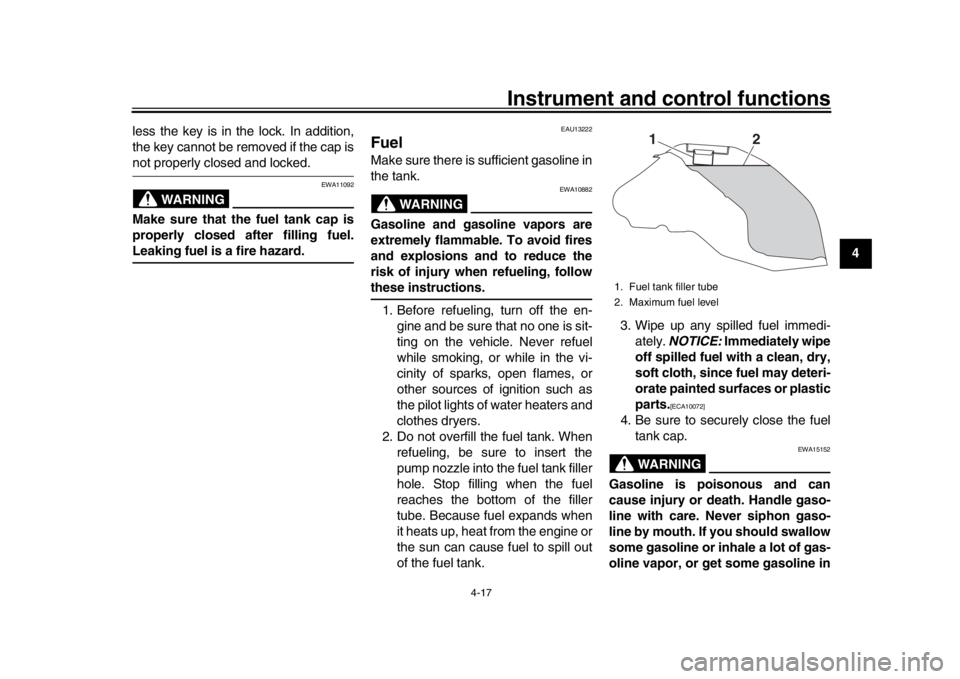
2. Do not overfill the fuel tank. When refueling, be sure to insert the
pump nozzle into the fuel tank filler
hole. Stop filling when the fuel
reaches the bottom of the filler
tube. Because fuel expands when
it heats up, heat from the engine or
the sun can cause fuel to spill out
of the fuel tank. 3. Wipe up any spilled fuel immedi-
ately. NOTICE: Immediately wipe
off spilled fuel with a clean, dry,
soft cloth, since fuel may deteri-
orate painted surfaces or plastic
parts.
[ECA10072]
4. Be sure to securely close the fuel tank cap.
WARNING
EWA15152
Gasoline is poisonous and can
cause injury or death. Handle gaso-
line with care. Never siphon gaso-
line by mouth. If you should swallow
some gasoline or inhale a lot of gas-
oline vapor, or get some gasoline in1. Fuel tank filler tube
2. Maximum fuel level
1
2
BS2-9-E2.book 17 ページ 2018年8月10日 金曜日 午前9時36分
Page 37 of 104

Instrument and control functions
4-19
1
2
345
6
7
8
9
10
11
12
EAU72972
Fuel tank overflow hoseBefore operating the vehicle:
Check the overflow hose connec-
tion and for damage.
Confirm the overflow hose is not
blocked and is routed through the
clamp.
TIPSee page 7-11 for canister information.
EAU13434
Catalytic converterThis model is equipped with a catalytic
converter in the exhaust system.
WARNING
EWA10863
The exhaust system is hot after op-
eration. To prevent a fire hazard or
burns:
Do not park the vehicle near
possible fire hazards such as
grass or other materials that
easily burn.
Park the vehicle in a place
where pedestrians or children
are not likely to touch the hot
exhaust system.
Make sure that the exhaust sys-
tem has cooled down before do-
ing any maintenance work.
Do not allow the engine to idle
more than a few minutes. Long
idling can cause a build-up ofheat.
NOTICE
ECA10702
Use only unleaded gasoline. The use
of leaded gasoline will cause unre- pairable damage to the catalytic
converter.
1. Fuel tank overflow hose
2. Clamp
21
BS2-9-E2.book 19 ページ 2018年8月10日 金曜日 午前9時36分
Page 38 of 104
Instrument and control functions
4-20
1
2
34
5
6
7
8
9
10
11
12
EAU57991
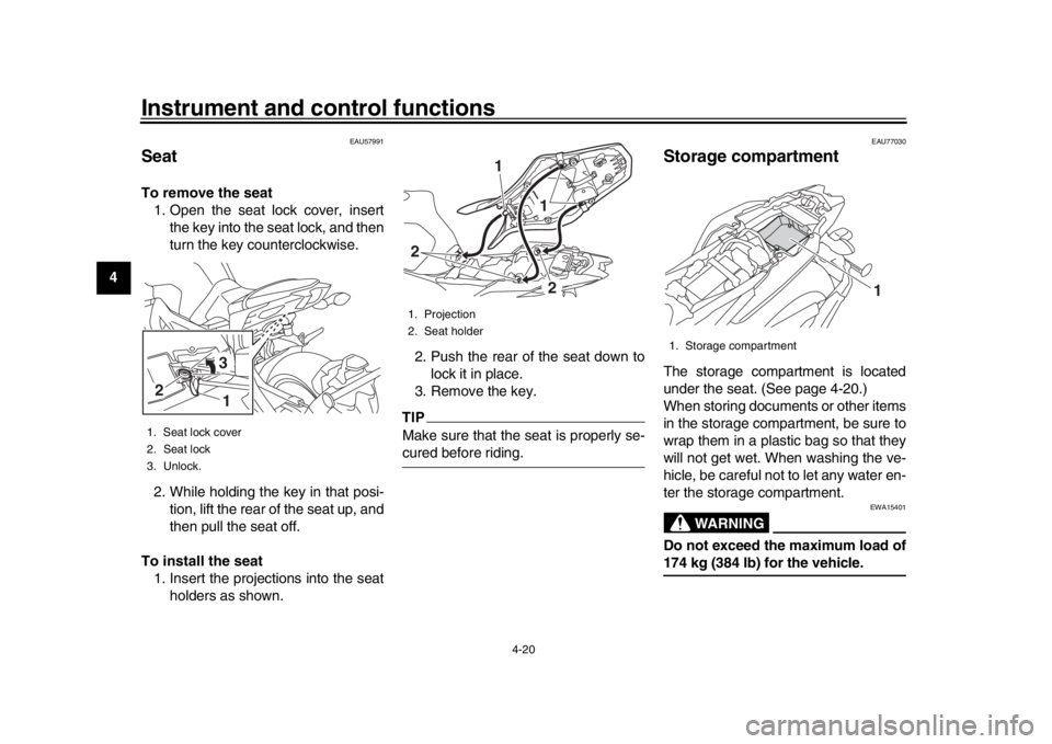
SeatTo remove the seat 1. Open the seat lock cover, insert the key into the seat lock, and then
turn the key counterclockwise.
2. While holding the key in that posi- tion, lift the rear of the seat up, and
then pull the seat off.
To install the seat 1. Insert the projections into the seat holders as shown. 2. Push the rear of the seat down to
lock it in place.
3. Remove the key.
TIPMake sure that the seat is properly se-cured before riding.
EAU77030
Storage compartmentThe storage compartment is located
under the seat. (See page 4-20.)
When storing documents or other items
in the storage compartment, be sure to
wrap them in a plastic bag so that they
will not get wet. When washing the ve-
hicle, be careful not to let any water en-
ter the storage compartment.
WARNING
EWA15401
Do not exceed the maximum load of174 kg (384 lb) for the vehicle.
1. Seat lock cover
2. Seat lock
3. Unlock.2
31
1. Projection
2. Seat holder
1
2
21
1. Storage compartment
1
BS2-9-E2.book 20 ページ 2018年8月10日 金曜日 午前9時36分
Page 39 of 104
Instrument and control functions
4-21
1
2
345
6
7
8
9
10
11
12
EAU76342
Adjusting the front fork
WARNING
EWA14671
Always adjust the spring preload on
both fork legs equally, otherwise
poor handling and loss of stabilitymay result.
Each front fork leg is equipped with a
spring preload adjusting bolt, the right
front fork leg is equipped with a re-
bound damping force adjusting screw
and the left front fork leg with a com-
pression damping force adjusting
screw.NOTICE
ECA10102
To avoid damaging the mechanism,
do not attempt to turn beyond themaximum or minimum settings.
Spring preload
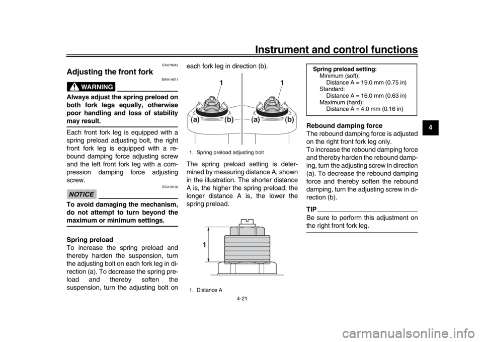
To increase the spring preload and
thereby harden the suspension, turn
the adjusting bolt on each fork leg in di-
rection (a). To decrease the spring pre-
load and thereby soften the
suspension, turn the adjusting bolt on each fork leg in direction (b).
The spring preload setting is deter-
mined by measuring distance A, shown
in the illustration. The shorter distance
A is, the higher the spring preload; the
longer distance A is, the lower the
spring preload.
Rebound damping force
The rebound damping force is adjusted
on the right front fork leg only.
To increase the rebound damping force
and thereby harden the rebound damp-
ing, turn the adjusting screw in direction
(a). To decrease the rebound damping
force and thereby soften the rebound
damping, turn the adjusting screw in di-
rection (b).
TIPBe sure to perform this adjustment onthe right front fork leg.
1. Spring preload adjusting bolt
1. Distance A
1
1
(a)
(b)
(a)
(b)
1
Spring preload setting:
Minimum (soft):Distance A = 19.0 mm (0.75 in)
Standard:
Distance A = 16.0 mm (0.63 in)
Maximum (hard): Distance A = 4.0 mm (0.16 in)
BS2-9-E2.book 21 ページ 2018年8月10日 金曜日 午前9時36分
Page 42 of 104
Instrument and control functions
4-24
1
2
34
5
6
7
8
9
10
11
12 settings, turn the adjuster in direc-
tion (a) until it stops, and then
count the turns in direction (b).
Although a damping force adjuster
may turn beyond the stated mini-
mum settings, such adjustments
are ineffective and may damagethe suspension.WARNING
EWA10222
This shock absorber assembly con-
tains highly pressurized nitrogen
gas. Read and understand the fol-
lowing information before handling
the shock absorber assembly.
Do not tamper with or attempt to
open the cylinder assembly.
Do not subject the shock ab-
sorber assembly to an open
flame or other high heat source.
This may cause the unit to ex-
plode due to excessive gas
pressure.
Do not deform or damage the
cylinder in any way. Cylinder
damage will result in poor
damping performance.
Do not dispose of a damaged or worn-out shock absorber as-
sembly yourself. Take the shock
absorber assembly to a Yamaha
dealer for any service.
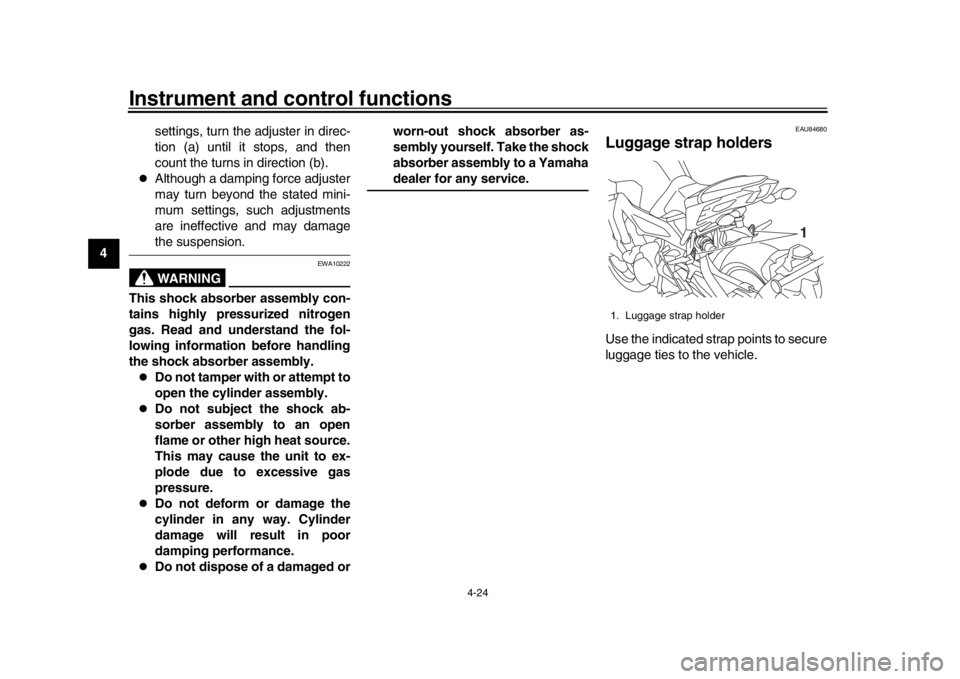
EAU84680
Luggage strap holdersUse the indicated strap points to secure
luggage ties to the vehicle.1. Luggage strap holder
1
BS2-9-E2.book 24 ページ 2018年8月10日 金曜日 午前9時36分
Page 43 of 104

Instrument and control functions
4-25
1
2
345
6
7
8
9
10
11
12
EAU77390
Auxiliary DC connectorsThis vehicle is equipped with an auxilia-
ry DC connector and a grip warmer DC
connector. Consult your Yamaha deal-
er before installing any accessories.
EAU15306
SidestandThe sidestand is located on the left side
of the frame. Raise the sidestand or
lower it with your foot while holding the
vehicle upright.TIPThe built-in sidestand switch is part of
the ignition circuit cut-off system, which
cuts the ignition in certain situations.
(See the following section for an expla-
nation of the ignition circuit cut-off sys-tem.)
WARNING
EWA10242
The vehicle must not be ridden with
the sidestand down, or if the sides-
tand cannot be properly moved up
(or does not stay up), otherwise the
sidestand could contact the ground
and distract the operator, resulting
in a possible loss of control.
Yamaha’s ignition circuit cut-off
system has been designed to assist
the operator in fulfilling the respon-
sibility of raising the sidestand be-
fore starting off. Therefore, check
this system regularly and have a Yamaha dealer repair it if it does not
function properly.
BS2-9-E2.book 25 ページ 2018年8月10日 金曜日 午前9時36分
Page 45 of 104

Instrument and control functions
4-27
1
2
345
6
7
8
9
10
11
12
With the engine turned off:
1. Move the sidestand down.
2. Set engine stop s witch to run position.
3. T urn m ain switch to on position.
4. Shift tr ansmission into neutr al.
5. Push the start switch.
Does the engine start?
With the engine still r unning:
6. Move the sidestand up.
7. Pull the clutch lever.
8. Shift tr ansmission into gear.
9. Move the sidestand down.
Does the en gine stall?
After the engine has stalled:
10.
Move the sidestand up.
11. Pull the clutch lever.
12. Push the start switch.
Does the engine start?
The system is OK. The motorcycle can be ridden.
YES NO
YES
NO
YES
NO
The neutral switch ma y not be working.
The motorcycle should not be ridden until
checked b y a Yamaha dealer.
The clutch s witch may not be working.
The motorcycle should not be ridden until
checked b y a Yamaha dealer.The sidestand s witch may not be working.
The motorcycle should not be ridden until
checked b y a Yamaha dealer.If a malfunction is found, have the vehicle
inspected before riding.
WARNING
BS2-9-E2.book 27 ページ 2018年8月10日 金曜日 午前9時36分
Page 46 of 104

5-1
1
2
3
45
6
7
8
9
10
11
12
For your safety – pre-operation checks
EAU15599
Inspect your vehicle each time you use it to make sure the vehi cle is in safe operating condition. Always follow the inspection
and maintenance procedures and schedules described in the Owner’s Manual.
WARNING
EWA11152
Failure to inspect or maintain the vehicle properly increases the possibility of an accident or equipment damage.
Do not operate the vehicle if you find any problem. If a problem cannot be corrected by the procedures provided inthis manual, have the vehicle inspected by a Yamaha dealer.
Before using this vehicle, check the following points:
ITEM CHECKS PAGE
Fuel Check fuel level in fuel tank.
Refuel if necessary.
Check fuel line for leakage.
Check fuel tank breather hose and overflow hose for obstructions, cracks or
damage, and check hose connections. 4-17, 4-19
Engine oil Check oil level in engine.
If necessary, add recommended oil to specified level.
Check vehicle for oil leakage. 7-11
Coolant Check coolant level in reservoir.
If necessary, add recommended coolant to specified level.
Check cooling system for leakage. 7-14
Front brake Check operation.
If soft or spongy, have Yamaha dealer bleed hydraulic system.
Check brake pads for wear.
Replace if necessary.
Check fluid level in reservoir.
If necessary, add specified brake fluid to specified level.
Check hydraulic system for leakage. 7-21, 7-22
BS2-9-E2.book 1 ページ 2018年8月10日 金曜日 午前9時36分