fuel cap YAMAHA MT-09 2019 Owners Manual
[x] Cancel search | Manufacturer: YAMAHA, Model Year: 2019, Model line: MT-09, Model: YAMAHA MT-09 2019Pages: 104, PDF Size: 7.14 MB
Page 6 of 104

Table of contentsSafety information........................... 1-1
Description ....................................... 2-1
Left view ......................................... 2-1
Right view ....................................... 2-2
Controls and instruments................ 2-3
Special features ............................... 3-1
D-mode (drive mode)...................... 3-1
Traction control system .................. 3-1
Quick shift system ...... .................... 3-3
Instrument and co ntrol functions... 4-1
Immobilizer system ..... .................... 4-1
Main switch/steering lock................ 4-2
Handlebar switches ........................ 4-3
Indicator lights and warning lights ............................................ 4-5
Multi-function meter unit ................. 4-7
Clutch lever................................... 4-14
Shift pedal..... ............................ .... 4-14
Brake lever ................................... 4-14
Brake pedal .................................. 4-15
ABS .............................................. 4-15
Fuel tank cap ................................ 4-16
Fuel............................................... 4-17
Fuel tank overflow hose................ 4-19
Catalytic converter ........................ 4-19
Seat .............................................. 4-20
Storage compartment ................... 4-20
Adjusting the front fork.................. 4-21 Adjusting the shock absorber
assembly................................... 4-23
Luggage strap holders . ................ 4-24
Auxiliary DC connectors ............... 4-25
Sidestand ..................................... 4-25
Ignition circuit cut- off system ........ 4-26
For your safety – pre-operation
checks .............................................. 5-1
Operation and important riding
points ................................................ 6-1
Starting the engine ......................... 6-1
Shifting ........................................... 6-2
Tips for reducing fuel consumption ............................... 6-3
Engine break-in .............................. 6-3
Parking ........................................... 6-4
Periodic maintenance and
adjustment ....................................... 7-1
Tool kit............................................ 7-2
Periodic maintenance charts .......... 7-3
Periodic maintenance chart for the emission control system ............. 7-3
General maintenance and lubrication chart .......................... 7-5
Removing and installing the
panel ........................................... 7-9
Checking the spark plugs ............. 7-10
Canister ........................................ 7-11 Engine oil ..................................... 7-11
Why Yamalube ............................ 7-14
Coolant ........................................ 7-14
Air filter element ........................... 7-16
Checking the engine idling
speed............ ............................ 7-16
Checking the throttle grip free play ........................................... 7-16
Valve clearance ........................... 7-17
Tires ............................................. 7-17
Cast wheels ................................. 7-19
Adjusting the clutch lever free play ........................................... 7-20
Checking the brake lever free
play ........................................... 7-20
Brake light switches ..................... 7-21
Checking the front and rear
brake pads................................ 7-21
Checking the brake fluid level ...... 7-22
Changing the brake fluid .............. 7-23
Drive chain slack.......................... 7-24
Cleaning and lubricating the drive chain ................................ 7-25
Checking and lubricating the cables ....................................... 7-26
Checking and lubricating the throttle grip and cable ............... 7-26
Checking and lubricating the
brake and shift pedals .............. 7-27
Checking and lubricating the brake and clutch levers ............ 7-27BS2-9-E2.book 1 ページ 2018年8月10日 金曜日 午前9時36分
Page 14 of 104

Description
2-2
12
3
4
5
6
7
8
9
10
11
12
EAU10421
Right view
2
1
6
7
8
9
10
5 3, 4
1. Fuses (page 7-31)
2. Fuel tank cap (page 4-16)
3. Spring preload adjuster (page 4-21)
4. Rebound damping force adjuster (page 4-21)
5. Coolant reservoir (page 7-14)
6. Engine oil level check window (page 7-11)
7. Engine oil filler cap (page 7-11)
8. Brake pedal (page 4-15)
9. Rear brake light switch (page 7-21)
10.Rear brake fluid reservoir (page 7-22)
BS2-9-E2.book 2 ページ 2018年8月10日 金曜日 午前9時36分
Page 34 of 104

Instrument and control functions
4-16
1
2
34
5
6
7
8
9
10
11
12
TIP
The ABS performs a self-diagno-
sis test each time the vehicle first
starts off after the key is turned to
“ON” and the vehicle has traveled
at a speed of 10 km/h (6 mi/h) or
higher. During this test, a “clicking”
noise can be heard from the hy-
draulic control unit, and if the brake
lever or brake pedal is even slight-
ly applied, a vibration can be felt at
the lever and pedal, but these do
not indicate a malfunction.
This ABS has a test mode which
allows the owner to experience the
pulsation at the brake lever or
brake pedal when the ABS is oper-
ating. However, special tools are
required, so please consult yourYamaha dealer.
NOTICE
ECA20100
Be careful not to damage the wheel
sensor or wheel sensor rotor; other-
wise, improper performance of theABS will result.
EAU13076
Fuel tank capTo open the fuel tank cap
Open the fuel tank cap lock cover, in-
sert the key into the lock, and then turn
it 1/4 turn clockwise. The lock will be re-
leased and the fuel tank cap can be
opened.
To close the fuel tank cap
With the key still inserted in the lock,
push down the fuel tank cap. Turn the
key 1/4 turn counterclockwise, remove
it, and then close the lock cover.TIPThe fuel tank cap cannot be closed un-
1. Front wheel sensor
2. Front wheel sensor rotor
1. Rear wheel sensor
2. Rear wheel sensor rotor
1
2
1
2
1. Fuel tank cap lock cover
2. Unlock.
1
2
BS2-9-E2.book 16 ページ 2018年8月10日 金曜日 午前9時36分
Page 35 of 104

Instrument and control functions
4-17
1
2
345
6
7
8
9
10
11
12
less the key is in the lock. In addition,
the key cannot be removed if the cap is
not properly closed and locked.
WARNING
EWA11092
Make sure that the fuel tank cap is
properly closed after filling fuel.Leaking fuel is a fire hazard.
EAU13222
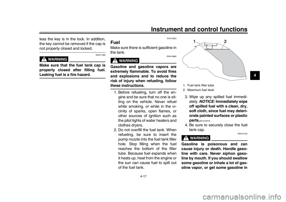
FuelMake sure there is sufficient gasoline in
the tank.
WARNING
EWA10882
Gasoline and gasoline vapors are
extremely flammable. To avoid fires
and explosions and to reduce the
risk of injury when refueling, followthese instructions.
1. Before refueling, turn off the en- gine and be sure that no one is sit-
ting on the vehicle. Never refuel
while smoking, or while in the vi-
cinity of sparks, open flames, or
other sources of ignition such as
the pilot lights of water heaters and
clothes dryers.
2. Do not overfill the fuel tank. When refueling, be sure to insert the
pump nozzle into the fuel tank filler
hole. Stop filling when the fuel
reaches the bottom of the filler
tube. Because fuel expands when
it heats up, heat from the engine or
the sun can cause fuel to spill out
of the fuel tank. 3. Wipe up any spilled fuel immedi-
ately. NOTICE: Immediately wipe
off spilled fuel with a clean, dry,
soft cloth, since fuel may deteri-
orate painted surfaces or plastic
parts.
[ECA10072]
4. Be sure to securely close the fuel tank cap.
WARNING
EWA15152
Gasoline is poisonous and can
cause injury or death. Handle gaso-
line with care. Never siphon gaso-
line by mouth. If you should swallow
some gasoline or inhale a lot of gas-
oline vapor, or get some gasoline in1. Fuel tank filler tube
2. Maximum fuel level
1
2
BS2-9-E2.book 17 ページ 2018年8月10日 金曜日 午前9時36分
Page 36 of 104

Instrument and control functions
4-18
1
2
34
5
6
7
8
9
10
11
12 your eyes, see your doctor immedi-
ately. If gasoline spills on your skin,
wash with soap and water. If gaso-
line spills on your clothing, change
your clothes.
EAU75300
NOTICE
ECA11401
Use only unleaded gasoline. The use
of leaded gasoline will cause severe
damage to internal engine parts,
such as the valves and piston rings,as well as to the exhaust system.
TIP
This mark identifies the recom-
mended fuel for this vehicle as
specified by European regulation
(EN228).
Check that gasoline nozzle has thesame identifier when fueling.
Your Yamaha engine has been de-
signed to use premium unleaded gaso-
line with a research octane number of
95 or higher. If knocking (or pinging) oc-
curs, use a gasoline of a different
brand. Use of unleaded fuel will extend
spark plug life and reduce maintenance
costs.
Gasohol
There are two types of gasohol: gaso- hol containing ethanol and that contain-
ing methanol. Gasohol containing
ethanol can be used if the ethanol con-
tent does not exceed 10% (E10). Gas-
ohol containing methanol is not
recommended by Yamaha because it
can cause damage to the fuel system
or vehicle performance problems.
Recommended fuel:
Premium unleaded gasoline (Gaso-
hol [E10] acceptable)
Fuel tank capacity: 14 L (3.7 US gal, 3.1 Imp.gal)
Fuel reserve amount:
2.8 L (0.74 US gal, 0.62 Imp.gal)
E5
E10
BS2-9-E2.book 18 ページ 2018年8月10日 金曜日 午前9時36分
Page 63 of 104

Periodic maintenance and adjustment7-11
1
2
3
4
5
678
9
10
11
12
installing a spark plug, a good estimate
of the correct torque is 1/4–1/2 turn
past finger tight. However, the spark
plug should be tightened to the speci-
fied torque as soon as possible.NOTICE
ECA10841
Do not use any tools to remove or in-
stall the spark plug cap, otherwise
the ignition coil coupler may get
damaged. The spark plug cap may
be difficult to remove because the
rubber seal on the end of the cap fits
tightly. To remove the spark plug
cap, simply twist it back and forth
while pulling it out; to install it, twistit back and forth while pushing it in.
EAU36112
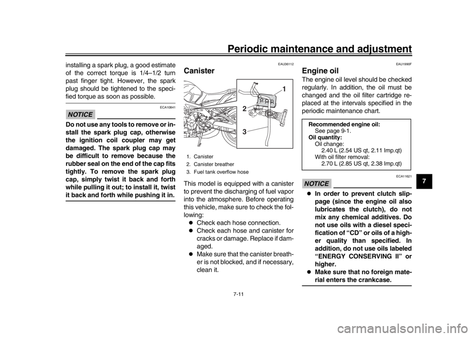
CanisterThis model is equipped with a canister
to prevent the discharging of fuel vapor
into the atmosphere. Before operating
this vehicle, make sure to check the fol-
lowing:
Check each hose connection.
Check each hose and canister for
cracks or damage. Replace if dam-
aged.
Make sure that the canister breath-
er is not blocked, and if necessary,
clean it.
EAU1990F
Engine oilThe engine oil level should be checked
regularly. In addition, the oil must be
changed and the oil filter cartridge re-
placed at the intervals specified in the
periodic maintenance chart.NOTICE
ECA11621
In order to prevent clutch slip-
page (since the engine oil also
lubricates the clutch), do not
mix any chemical additives. Do
not use oils with a diesel speci-
fication of “CD” or oils of a high-
er quality than specified. In
addition, do not use oils labeled
“ENERGY CONSERVING II” or
higher.
Make sure that no foreign mate-rial enters the crankcase.
1. Canister
2. Canister breather
3. Fuel tank overflow hose
1
2
3
Recommended engine oil: See page 9-1.
Oil quantity: Oil change:2.40 L (2.54 US qt, 2.11 Imp.qt)
With oil filter removal: 2.70 L (2.85 US qt, 2.38 Imp.qt)
BS2-9-E2.book 11 ページ 2018年8月10日 金曜日 午前9時36分
Page 94 of 104

Motorcycle care and storage
8-4
1
2
3
4
5
6
78
9
10
11
12 perform any outstanding mainte-
nance.
2. Follow all instructions in the Care section of this chapter.
3. Fill up the fuel tank, adding fuel stabilizer according to product in-
structions. Run the engine for 5
minutes to distribute treated fuel
through the fuel system.
4. For vehicles equipped with a fuel cock: Turn the fuel cock lever to
the off position.
5. For vehicles with a carburetor: To prevent fuel deposits from building
up, drain the fuel in the carburetor
float chamber into a clean contain-
er. Retighten the drain bolt and
pour the fuel back into the fuel
tank.
6. Use a quality engine fogging oil ac- cording to product instructions to
protect internal engine compo-
nents from corrosion. If engine fog-
ging oil is not available, perform
the following steps for each cylin-
der:
a. Remove the spark plug cap and spark plug.
b. Pour a teaspoonful of engine oil into the spark plug bore.
c. Install the spark plug cap onto the spark plug, and then place
the spark plug on the cylinder
head so that the electrodes are
grounded. (This will limit spark-
ing during the next step.)
d. Turn the engine over several times with the starter. (This will
coat the cylinder wall with oil.)
WARNING! To prevent dam-
age or injury from sparking,
make sure to ground the
spark plug electrodes while
turning the engine
over.
[EWA10952]
e. Remove the spark plug capfrom the spark plug, and then
install the spark plug and the
spark plug cap.
7. Lubricate all control cables, pivots, levers and pedals, as well as the
sidestand and centerstand (if
equipped).
8. Check and correct the tire air pres- sure, and then lift the vehicle so
that all wheels are off the ground.
Otherwise, turn the wheels a little
once a month in order to prevent the tires from becoming degraded
in one spot.
9. Cover the muffler outlet with a plastic bag to prevent moisture
from entering it.
10. Remove the battery and fully charge it, or attach a maintenance
charger to keep the battery opti-
mally charged. NOTICE: Confirm
that the battery and its charger
are compatible. Do not charge a
VRLA battery with a convention-
al charger.
[ECA26330]
TIP
If the battery will be removed,
charge it once a month and store it
in a temperate location between
0-30 C (32-90 F).
See page 7-30 for more informa-
tion on charging and storing thebattery.
BS2-9-E2.book 4 ページ 2018年8月10日 金曜日 午前9時36分
Page 95 of 104

9-1
1
2
3
4
5
6
7
8910
11
12
Specifications
EAU84802
Dimensions:Overall length:2075 mm (81.7 in)
Overall width: 815 mm (32.1 in)
Overall height: 1120 mm (44.1 in)
Seat height:
820 mm (32.3 in)
Wheelbase: 1440 mm (56.7 in)
Ground clearance: 135 mm (5.31 in)
Minimum turning radius:
3.0 m (9.84 ft)Weight:Curb weight:193 kg (425 lb)Engine:Combustion cycle:4-stroke
Cooling system: Liquid cooled
Valve train:
DOHC
Cylinder arrangement: Inline
Number of cylinders: 3-cylinder
Displacement:
847 cm
3
Bore stroke:
78.0 59.1 mm (3.07 2.33 in) Starting system:
Electric starter
Engine oil:Recommended brand:
SAE viscosity grades:10W-40
Recommended engine oil grade: API service SG type or higher, JASO stan-
dard MA
Engine oil quantity: Oil change:2.40 L (2.54 US qt, 2.11 Imp.qt)
With oil filter removal: 2.70 L (2.85 US qt, 2.38 Imp.qt)Coolant quantity:Coolant reservoir (up to the maximum level
mark):
0.25 L (0.26 US qt, 0.22 Imp.qt)
Radiator (including all routes): 1.93 L (2.04 US qt, 1.70 Imp.qt)Fuel:Recommended fuel:
Premium unleaded gasoline (Gasohol
[E10] acceptable)
Fuel tank capacity:
14 L (3.7 US gal, 3.1 Imp.gal)
Fuel reserve amount: 2.8 L (0.74 US gal, 0.62 Imp.gal)
Fuel injection:Throttle body:
ID mark:B901 00Drivetrain:Gear ratio:
1st: 2.667 (40/15)
2nd: 2.000 (38/19)
3rd: 1.619 (34/21)
4th:
1.381 (29/21)
5th: 1.190 (25/21)
6th: 1.037 (28/27)Front tire:Type:Tubeless
Size: 120/70 ZR17 M/C (58W)
Manufacturer/model:
BRIDGESTONE/S20F
Manufacturer/model: DUNLOP/D214FRear tire:Type:
Tubeless
Size: 180/55 ZR17M/C (73W)
Manufacturer/model: BRIDGESTONE/S20R
BS2-9-E2.book 1 ページ 2018年8月10日 金曜日 午前9時36分
Page 100 of 104

11-1
1
2
3
4
5
6
7
8
9
1011
12
IndexAABS ....................................................... 4-15
ABS warning light.................................... 4-6
Air filter element .................................... 7-16
Auxiliary DC connectors........................ 4-25BBattery................................................... 7-30
Brake and clutch levers, checking and lubricating ........................................... 7-27
Brake and shift pedals, checking and
lubricating ........................................... 7-27
Brake fluid, changing ............................ 7-23
Brake fluid level, checking .................... 7-22
Brake lever ............................................ 4-14
Brake lever free play, checking ............. 7-20
Brake light switches .............................. 7-21
Brake pedal ........................................... 4-15CCables, checking and lubricating .......... 7-26
Canister................................................. 7-11
Care ........................................................ 8-1
Catalytic converter ................................ 4-19
Clutch lever ........................................... 4-14
Clutch lever free play, adjusting ............ 7-20
Coolant.................................................. 7-14
Coolant temperature warning light .......... 4-5DData recording, vehicle ......................... 10-2
Diagnostic connector ............................ 10-2
Dimmer switch ........................................ 4-4
D-mode (drive mode) .............................. 3-1
Drive chain, cleaning and lubricating .... 7-25
Drive chain slack ................................... 7-24
Drive mode switch................................... 4-4
EEngine break-in ...................................... 6-3
Engine idling speed, checking .............. 7-16
Engine oil .............................................. 7-11
Engine serial number............................ 10-1
Engine trouble warning light ................... 4-6FFront and rear brake pads, checking .... 7-21
Front fork, adjusting .............................. 4-21
Front fork, checking .............................. 7-29
Fuel....................................................... 4-17
Fuel consumption, tips for reducing........ 6-3
Fuel tank cap ........................................ 4-16
Fuel tank overflow hose........................ 4-19
Fuses, replacing ................................... 7-31HHandlebar switches ................................ 4-3
Hazard switch ......................................... 4-4
High beam indicator light ........................ 4-5
Horn switch ............................................. 4-4IIdentification numbers .......................... 10-1
Ignition circuit cut-off system ................ 4-26
Immobilizer system ................................. 4-1
Immobilizer system indicator light........... 4-6
Indicator lights and warning lights .......... 4-5LLuggage strap holders .......................... 4-24MMain switch/steering lock........................ 4-2
Maintenance and lubrication, periodic .... 7-5
Maintenance, emission control system... 7-3
Matte color, caution ................................ 8-1
Model label ........................................... 10-2 Multi-function meter unit .......................... 4-7
NNeutral indicator light .............................. 4-5OOil level warning light .............................. 4-5PPanel, removing and installing ................ 7-9
Parking .................................................... 6-4
Part locations .......................................... 2-1
Pass switch ............................................. 4-4QQuick shift indicator light ......................... 4-6
Quick shift system ................................... 3-3SSafety information ................................... 1-1
Seat ....................................................... 4-20
Shifting .................................................... 6-2
Shift pedal ............................................. 4-14
Shock absorber assembly, adjusting .... 4-23
Sidestand .............................................. 4-25
Sidestand, checking an
d lubricating...... 7-28
Spark plugs, checking ........................... 7-10
Special features ...................................... 3-1
Specifications .......................................... 9-1
Starting the engine .................................. 6-1
Steering, checking................................. 7-29
Stop/Run/Start switch.............................. 4-4
Storage.................................................... 8-3
Storage compartment............................ 4-20
Supporting the motorcycle .................... 7-35
Swingarm pivots, lubricating ................. 7-28TThrottle grip and cable, checking and
lubricating ........................................... 7-26
BS2-9-E2.book 1 ページ 2018年8月10日 金曜日 午前9時36分