diagnostic menu YAMAHA MT-09 2022 Owners Manual
[x] Cancel search | Manufacturer: YAMAHA, Model Year: 2022, Model line: MT-09, Model: YAMAHA MT-09 2022Pages: 110, PDF Size: 3.8 MB
Page 41 of 110

Instrument and control functions
4-20
4
EAU91461
Brake control system (BC)The brake control system regulates hy-
draulic brake pressure for the front and
rear wheels independently when the
brakes are applied and wheel lock is
detected. This system has two settings
which can be changed in the settings
MENU. (See page 4-15.)
BC1 is standard ABS, which adjusts
brake pressure based on vehicle
speed and wheel speed data. BC1 is
designed to engage and maximize
braking when the vehicle is upright.
BC2 uses additional data from the IMU
to regulate applied brake power when
cornering to suppress lateral wheel
slip.
Regarding ABS, operate the brakes as
you would conventional brakes. When
the brake control system engages, a
pulsating sensation may be felt at the
brake lever or brake pedal as the hy-
draulic unit rapidly applies and reduces
brake pressure. In this situation, con-
tinue to apply the brake lever and
brake pedal to allow the ABS to work—
do not “pump the brakes” as this will
reduce braking effectiveness.
WARNING
EWA16051
Always keep a sufficient d istance
from the vehicle ahead to match the
ri din g speed even with ABS.
The ABS performs best with
lon g b rakin g d istances.
On certain surfaces, such as
rou gh or g ravel roa ds, the b rak-
in g d istance may be lon ger with
the ABS than without.The ABS hydraulic unit is monitored by
the ABS ECU, which will revert the sys-
tem to conventional braking if a mal-
function occurs.
WARNING
EWA20891
The brake control system is not a
su bstitute for the use of proper ri d-
in g an d brakin g techniques. The
b rake control system cannot pre-
vent all loss of traction due to over-
b rakin g from excessive spee d, or
lateral wheel slip when brakin g on
slippery surfaces.
TIPThe ABS performs a self-diagnostic
test when the vehicle is started and
reaches a speed of 5 km/h (3 mi/h).
During this test, a clicking noise may
be audible from the hydraulic control
unit, and a vibration may be felt at the
brake lever or pedal, but this is normal.NOTICE
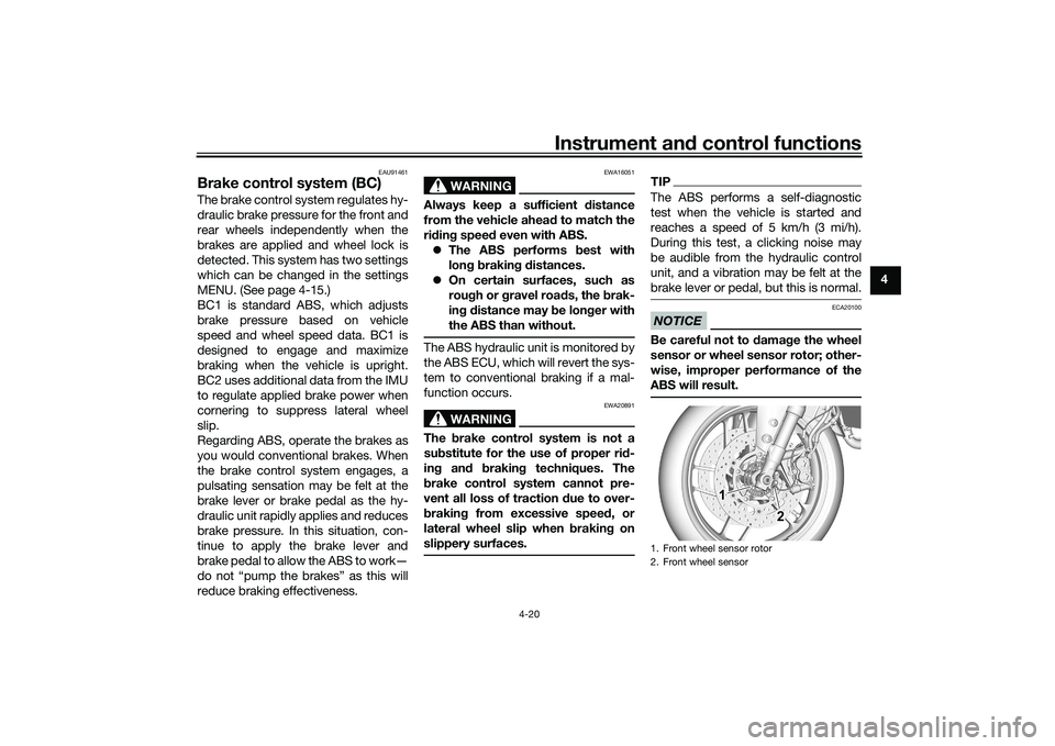
ECA20100
Be careful not to d amage the wheel
sensor or wheel sensor rotor; other-
wise, improper performance of the
ABS will result.1. Front wheel sensor rotor
2. Front wheel sensor
1 1 1
2 2
UB7NE1E0.book Page 20 Friday, September 3, 2021 11:25 AM
Page 106 of 110

11-1
11
IndexAABS warning light ................................... 4-7
Air filter element .................................... 7-14
Auxiliary DC connectors ....................... 4-30
Auxiliary system warning light ................ 4-8BBattery .................................................. 7-28
BC ........................................................... 3-4
Brake and clutch levers, checking
and lubricating .................................... 7-26
Brake and shift pedals, checking and lubricating ........................................... 7-25
Brake control system (BC) .................... 4-20
Brake fluid, changing ............................ 7-21
Brake fluid level, checking .................... 7-20
Brake lever ............................................ 4-19
Brake lever free play, checking............. 7-18
Brake light switches.............................. 7-19
Brake pedal........................................... 4-19CCables, checking and lubricating ......... 7-24
Canister................................................. 7-10
Care ........................................................ 8-1
Catalytic converter ................................ 4-24
Clutch lever ........................................... 4-18
Clutch lever free play, adjusting ........... 7-18
Coolant ................................................. 7-13DData recording, vehicle ......................... 10-2
Diagnostic connector............................ 10-2
Dimmer switch ........................................ 4-4
Display .................................................... 4-9
Display, menu screen ........................... 4-14
D-MODE ................................................. 3-1 Drive chain, cleaning and lubricating ... 7-24
Drive chain slack .................................. 7-22
EEngine break-in ...................................... 6-1
Engine idling speed, checking ............. 7-14
Engine oil .............................................. 7-10
Engine overheating ............................... 7-35
Engine serial number ............................ 10-1FFront and rear brake pads, checking ... 7-19
Front fork, adjusting ............................. 4-26
Front fork, checking ............................. 7-27
Fuel ....................................................... 4-22
Fuel consumption, tips for reducing ...... 6-4
Fuel level warning light ........................... 4-6
Fuel tank cap ........................................ 4-21
Fuel tank overflow hose ....................... 4-23
Fuses, replacing ................................... 7-30HHandlebar position, adjusting .............. 4-25
Handlebar switches ................................ 4-3
Hazard switch......................................... 4-4
High beam indicator light ....................... 4-6
Horn switch ............................................ 4-4IIdentification numbers .......................... 10-1
Ignition circuit cut-off system ............... 4-31
Immobilizer system ................................ 4-1
Immobilizer system indicator light .......... 4-7
Indicator lights and warning lights ......... 4-5LLicense plate light ................................ 7-32
Luggage strap holders ......................... 4-30
MMain switch/steering lock .......................4-2
Maintenance and lubrication, periodic....7-5
Maintenance, emission control
system ..................................................7-3
Malfunction indicator light (MIL)..............4-6
Matte color, caution ................................8-1
Model label ...........................................10-1NNeutral indicator light ..............................4-6OOil pressure and Coolant temperature warning light .........................................4-8PParking ....................................................6-5
Part locations ..........................................2-1
Pass switch .............................................4-4QQuick shifter ............................................3-3RRider footrest position, adjusting ..........4-25SSafety information ...................................1-1
Seat .......................................................4-24
Shifting ....................................................6-3
Shift pedal .............................................4-18
Shock absorber assembly, adjusting ....4-28
Sidestand ..............................................4-30
Sidestand, checking and lubricating.....7-26
Spark plugs, checking ............................7-9
Special features ......................................3-1
Specifications .........................................9-1
Stability control indicator light ................4-7
Starting the engine ..................................6-2
UB7NE1E0.book Page 1 Friday, September 3, 2021 11:25 AM