check engine YAMAHA MT-10 2018 User Guide
[x] Cancel search | Manufacturer: YAMAHA, Model Year: 2018, Model line: MT-10, Model: YAMAHA MT-10 2018Pages: 108, PDF Size: 8.97 MB
Page 49 of 108
Instrument and control functions
4-28
1
2
345
6
7
8
9
10
11
12
EAU49454
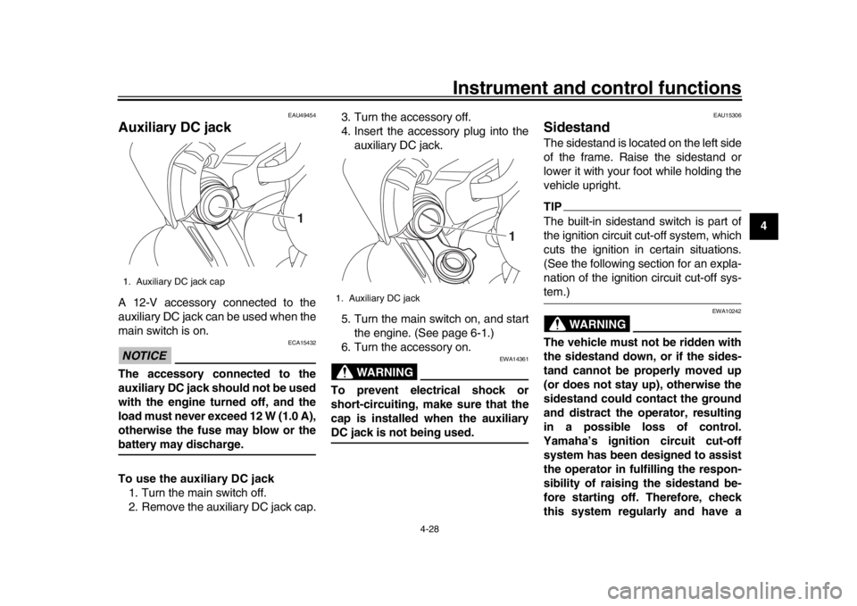
Auxiliary DC jackA 12-V accessory connected to the
auxiliary DC jack can be used when the
main switch is on.NOTICE
ECA15432
The accessory connected to the
auxiliary DC jack should not be used
with the engine turned off, and the
load must never exceed 12 W (1.0 A),
otherwise the fuse may blow or thebattery may discharge.
To use the auxiliary DC jack 1. Turn the main switch off.
2. Remove the auxiliary DC jack cap. 3. Turn the accessory off.
4. Insert the accessory plug into the
auxiliary DC jack.
5. Turn the main switch on, and start the engine. (See page 6-1.)
6. Turn the accessory on.
WARNING
EWA14361
To prevent electrical shock or
short-circuiting, make sure that the
cap is installed when the auxiliaryDC jack is not being used.
EAU15306
SidestandThe sidestand is located on the left side
of the frame. Raise the sidestand or
lower it with your foot while holding the
vehicle upright.TIPThe built-in sidestand switch is part of
the ignition circuit cut-off system, which
cuts the ignition in certain situations.
(See the following section for an expla-
nation of the ignition circuit cut-off sys-tem.)
WARNING
EWA10242
The vehicle must not be ridden with
the sidestand down, or if the sides-
tand cannot be properly moved up
(or does not stay up), otherwise the
sidestand could contact the ground
and distract the operator, resulting
in a possible loss of control.
Yamaha’s ignition circuit cut-off
system has been designed to assist
the operator in fulfilling the respon-
sibility of raising the sidestand be-
fore starting off. Therefore, check
this system regularly and have a
1. Auxiliary DC jack cap
1
1. Auxiliary DC jack
1
B67-9-E2.book 28 ページ 2018年6月5日 火曜日 午前9時7分
Page 50 of 108
Instrument and control functions
4-29
1
2
34
5
6
7
8
9
10
11
12 Yamaha dealer repair it if it does not
function properly.
EAU57951
Ignition circuit cut-off systemThis system prevents in-gear engine
starts unless the clutch lever is pulled
and the sidestand is up. Also, it will stop
the running engine should the sides-
tand be lowered while the transmission
is in gear.
Periodically check the system via the
following procedure.TIP
This check is most reliable if per-
formed with a warmed-up engine.
See pages 4-2 and 4-3 for switchoperation information.
B67-9-E2.book 29 ページ 2018年6月5日 火曜日 午前9時7分
Page 51 of 108

Instrument and control functions
4-30
1
2
345
6
7
8
9
10
11
12
With the engine turned off:
1. Move the sidestand down.
2. Set engine stop s witch to run position.
3. T urn m ain switch to on position.
4. Shift tr ansmission into neutr al.
5. Push the start switch.
Does the engine start?
With the engine still r unning:
6. Move the sidestand up.
7. Pull the clutch lever.
8. Shift tr ansmission into gear.
9. Move the sidestand down.
Does the en gine stall?
After the engine has stalled:
10.
Move the sidestand up.
11. Pull the clutch lever.
12. Push the start switch.
Does the engine start?
The system is OK. The motorcycle can be ridden.
YES NO
YES
NO
YES
NO
The neutral switch ma y not be working.
The motorcycle should not be ridden until
checked b y a Yamaha dealer.
The clutch s witch may not be working.
The motorcycle should not be ridden until
checked b y a Yamaha dealer.The sidestand s witch may not be working.
The motorcycle should not be ridden until
checked b y a Yamaha dealer.If a malfunction is found, have the vehicle
inspected before riding.
WARNING
B67-9-E2.book 30 ページ 2018年6月5日 火曜日 午前9時7分
Page 52 of 108

5-1
1
2
3
45
6
7
8
9
10
11
12
For your safety – pre-operation checks
EAU15599
Inspect your vehicle each time you use it to make sure the vehi cle is in safe operating condition. Always follow the inspection
and maintenance procedures and schedules described in the Owner’s Manual.
WARNING
EWA11152
Failure to inspect or maintain the vehicle properly increases the possibility of an accident or equipment damage.
Do not operate the vehicle if you find any problem. If a problem cannot be corrected by the procedures provided inthis manual, have the vehicle inspected by a Yamaha dealer.
Before using this vehicle, check the following points:
ITEM CHECKS PAGE
Fuel Check fuel level in fuel tank.
Refuel if necessary.
Check fuel line for leakage.
Check fuel tank breather/overflow hose
for obstructions, cracks or damage, and
check hose connection. 4-19, 4-21
Engine oil Check oil level in engine.
If necessary, add recommended oil to specified level.
Check vehicle for oil leakage. 7-10
Coolant Check coolant level in reservoir.
If necessary, add recommended coolant to specified level.
Check cooling system for leakage. 7-14
Front brake Check operation.
If soft or spongy, have Yamaha dealer bleed hydraulic system.
Check brake pads for wear.
Replace if necessary.
Check fluid level in reservoir.
If necessary, add specified brake fluid to specified level.
Check hydraulic system for leakage. 7-21
B67-9-E2.book 1 ページ 2018年6月5日 火曜日 午前9時7分
Page 56 of 108
Operation and important riding points
6-2
1
2
3
4
56
7
8
9
10
11
12
NOTICE
ECA11834
If a warning or indicator light does
not come on initially when the key is
turned to “ON”, or if a warning or in-
dicator light remains on, see page
4-5 for the corresponding warningand indicator light circuit check. The ABS warning light should
come on when the key is turned to
“ON”, and then go off after travel-
ing at a speed of 10 km/h (6 mi/h)
or higher.NOTICE
ECA17682
If the ABS warning light does not
come on and then go off as ex-
plained above, see page 4-5 for thewarning light circuit check.2. Shift the transmission into the neu- tral position. The neutral indicator
light should come on. If not, ask a
Yamaha dealer to check the elec-
trical circuit.
3. Start the engine by pushing the “ ” side of the stop/run/start
switch.
If the engine fails to start, release the stop/run/start switch, wait a
few seconds, and then try again.
Each starting attempt should be as
short as possible to preserve the
battery. Do not crank the engine
more than 10 seconds on any one
attempt.
NOTICE
ECA11043
For maximum engine life, never ac-
celerate hard when the engine iscold!
EAU77400
ShiftingShifting gears lets you control the
amount of engine power available for
starting off, accelerating, climbing hills,
etc.
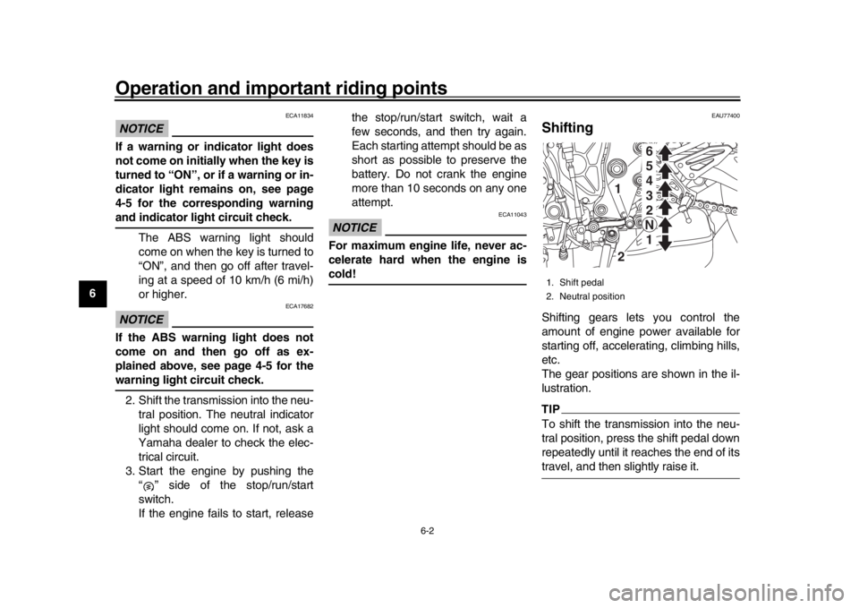
The gear positions are shown in the il-
lustration.TIPTo shift the transmission into the neu-
tral position, press the shift pedal down
repeatedly until it reaches the end of itstravel, and then slightly raise it.1. Shift pedal
2. Neutral position
6
5
4
3
2
N 1
1
2
B67-9-E2.book 2 ページ 2018年6月5日 火曜日 午前9時7分
Page 58 of 108
Operation and important riding points
6-4
1
2
3
4
56
7
8
9
10
11
12 r/min.
1600 km (1000 mi) and beyond
The vehicle can now be operated nor-
mally.
NOTICE
ECA10311
Keep the engine speed out of
the tachometer red zone.
If any engine trouble should oc-
cur during the engine break-in
period, immediately have a
Yamaha dealer check the vehi-cle.
TIPDuring and after the engine break-in
period, the exhaust heat may cause
discoloration of the exhaust pipe, butthis is normal.
EAU17214
ParkingWhen parking, stop the engine, and
then remove the key from the main
switch.
WARNING
EWA10312
Since the engine and exhaust
system can become very hot,
park in a place where pedestri-
ans or children are not likely to
touch them and be burned.
Do not park on a slope or on soft
ground, otherwise the vehicle
may overturn, increasing the
risk of a fuel leak and fire.
Do not park near grass or other
flammable materials whichmight catch fire.
B67-9-E2.book 4 ページ 2018年6月5日 火曜日 午前9時7分
Page 61 of 108

Periodic maintenance and adjustment
7-3
1
2
3
4
5
678
9
10
11
12
EAU71031
TIP
The annual checks must be performed every year, except if a distance-based maintenance is performed in-
stead.
From 50000 km (30000 mi), repeat the maintenance intervals starting from 10000 km (6000 mi).
Items marked with an asterisk should be performed by a Yamaha dealer as they require special tools, data and technicalskills.
EAU71051
Periodic maintenance chart for the emission control systemNO. ITEM CHECK OR MAINTENANCE JOB ODOMETER READING
ANNUAL
CHECK
1000 km
(600 mi) 10000 km
(6000 mi) 20000 km
(12000 mi) 30000 km
(18000 mi) 40000 km
(24000 mi)
1 *Fuel line Check fuel hoses for cracks or
damage.
Replace if necessary.
2 *Spark plugs Check condition.
Adjust gap and clean.
Replace.
3 *Valve clearance Check and adjust. Every 40000 km (24000 mi)
4 *Fuel injection Check engine idle speed.
Check and adjust synchronization.
5 *Exhaust system Check for leakage.
Tighten if necessary.
Replace gaskets if necessary.
6 *Evaporative
emission control
system Check control system for damage.
Replace if necessary.
B67-9-E2.book 3 ページ 2018年6月5日 火曜日 午前9時7分
Page 65 of 108

Periodic maintenance and adjustment
7-7
1
2
3
4
5
678
9
10
11
12
24 *Rear suspension
relay arm and
connecting arm
pivoting points Check operation.
25 Engine oil Change (warm engine before
draining).
Check oil level and vehicle for oil leakage.
26 Engine oil filter
cartridge Replace.
27 *Cooling system Check coolant level and vehicle
for coolant leakage.
Change. Every 3 years
28 *EXUP system Check operation, cable free play
and pulley position.
29 *Front and rear brake
switches Check operation.
30 *Moving parts and
cables Lubricate.
31 *Throttle grip
housing and cable Check operation and free play.
Adjust the throttle cable free play
if necessary.
Lubricate the throttle grip housing and cable.
32 *Lights, signals and
switches Check operation.
Adjust headlight beam.
NO. ITEM CHECK OR MAINTENANCE JOB
ODOMETER READING
ANNUAL
CHECK
1000 km
(600 mi) 10000 km
(6000 mi) 20000 km
(12000 mi) 30000 km
(18000 mi) 40000 km
(24000 mi)
B67-9-E2.book 7 ページ 2018年6月5日 火曜日 午前9時7分
Page 67 of 108

Periodic maintenance and adjustment
7-9
1
2
3
4
5
678
9
10
11
12
EAU67110
Checking the spark plugsThe spark plugs are important engine
components, which should be checked
periodically, preferably by a Yamaha
dealer. Since heat and deposits will
cause any spark plug to slowly erode,
they should be removed and checked
in accordance with the periodic mainte-
nance and lubrication chart. In addition,
the condition of the spark plugs can re-
veal the condition of the engine.
The porcelain insulator around the cen-
ter electrode of each spark plug should
be a medium-to-light tan (the ideal color
when the vehicle is ridden normally),
and all spark plugs installed in the en-
gine should have the same color. If any
spark plug shows a distinctly different
color, the engine could be operating im-
properly. Do not attempt to diagnose
such problems yourself. Instead, have
a Yamaha dealer check the vehicle.
If a spark plug shows signs of electrode
erosion and excessive carbon or other
deposits, it should be replaced. Before installing a spark plug, the spark
plug gap should be measured with a
wire thickness gauge and, if necessary,
adjusted to specification.
Clean the surface of the spark plug
gasket and its mating surface, and then
wipe off any grime from the spark plug
threads.
NOTICE
ECA10841
Do not use any tools to remove or in-
stall the spark plug cap, otherwise
the ignition coil coupler may get
damaged. The spark plug cap may
be difficult to remove because the
rubber seal on the end of the cap fits
tightly. To remove the spark plug
cap, simply twist it back and forth
while pulling it out; to install it, twistit back and forth while pushing it in.
Specified spark plug:
NGK/LMAR9E-J
1. Spark plug gapSpark plug gap:0.6–0.7 mm (0.024–0.028 in)
Tightening torque: Spark plug (new):18 N·m (1.8 kgf·m, 13 lb·ft)
Spark plug (after checking):
13 N·m (1.3 kgf·m, 9.6 lb·ft)
1
1
B67-9-E2.book 9 ページ 2018年6月5日 火曜日 午前9時7分
Page 68 of 108
Periodic maintenance and adjustment
7-10
1
2
3
4
5
67
8
9
10
11
12
EAU36112
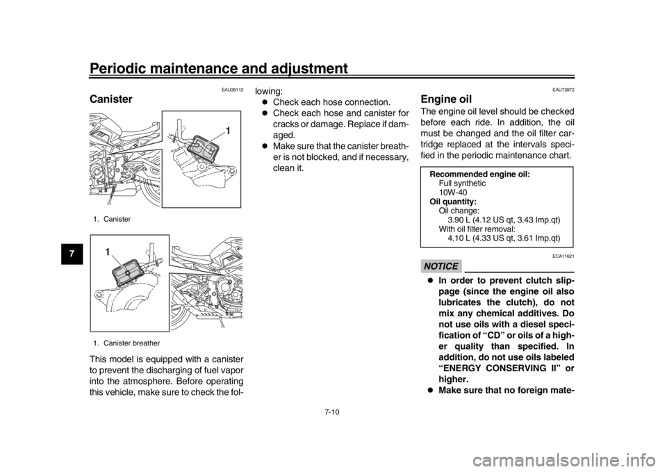
CanisterThis model is equipped with a canister
to prevent the discharging of fuel vapor
into the atmosphere. Before operating
this vehicle, make sure to check the fol- lowing:
Check each hose connection.
Check each hose and canister for
cracks or damage. Replace if dam-
aged.
Make sure that the canister breath-
er is not blocked, and if necessary,
clean it.
EAU73972
Engine oilThe engine oil level should be checked
before each ride. In addition, the oil
must be changed and the oil filter car-
tridge replaced at the intervals speci-
fied in the periodic maintenance chart.NOTICE
ECA11621
In order to prevent clutch slip-
page (since the engine oil also
lubricates the clutch), do not
mix any chemical additives. Do
not use oils with a diesel speci-
fication of “CD” or oils of a high-
er quality than specified. In
addition, do not use oils labeled
“ENERGY CONSERVING II” or
higher.
Make sure that no foreign mate-
1. Canister
1. Canister breather
1
1
Recommended engine oil:
Full synthetic
10W-40
Oil quantity: Oil change:
3.90 L (4.12 US qt, 3.43 Imp.qt)
With oil filter removal: 4.10 L (4.33 US qt, 3.61 Imp.qt)
B67-9-E2.book 10 ページ 2018年6月5日 火曜日 午前9時7分