Time YAMAHA MT-125 2015 User Guide
[x] Cancel search | Manufacturer: YAMAHA, Model Year: 2015, Model line: MT-125, Model: YAMAHA MT-125 2015Pages: 96, PDF Size: 7.28 MB
Page 42 of 96
OPERATION AND IMPORTANT RIDING POINTS
5-4
5500–1000 km (300–600 mi)
Avoid prolonged operation above 8000
r/min.
Rev the engine freely through the
gears, but do not use full throttle at any
time. NOTICE: After 1000 km (600 mi)
of operation, the engine oil must be
changed, the oil filter cartridge or el-
ement replaced, and the oil strainer
cleaned.
[ECA10322]
1000 km (600 mi) and beyond
The vehicle can now be operated nor-
mally.NOTICE
ECA10311
Keep the engine speed out of
the tachometer red zone.
If any engine trouble should oc-
cur during the engine break-in
period, immediately have a
Yamaha dealer check the vehi-
cle.
EAU17214
ParkingWhen parking, stop the engine, and
then remove the key from the main
switch.
WARNING
EWA10312
Since the engine and exhaust
system can become very hot,
park in a place where pedestri-
ans or children are not likely to
touch them and be burned.
Do not park on a slope or on soft
ground, otherwise the vehicle
may overturn, increasing the
risk of a fuel leak and fire.
Do not park near grass or other
flammable materials which
might catch fire.
U5D7E4E0.book Page 4 Thursday, July 10, 2014 3:01 PM
Page 50 of 96
PERIODIC MAINTENANCE AND ADJUSTMENT
6-8
6
EAU18782
Removing and installing cowl-
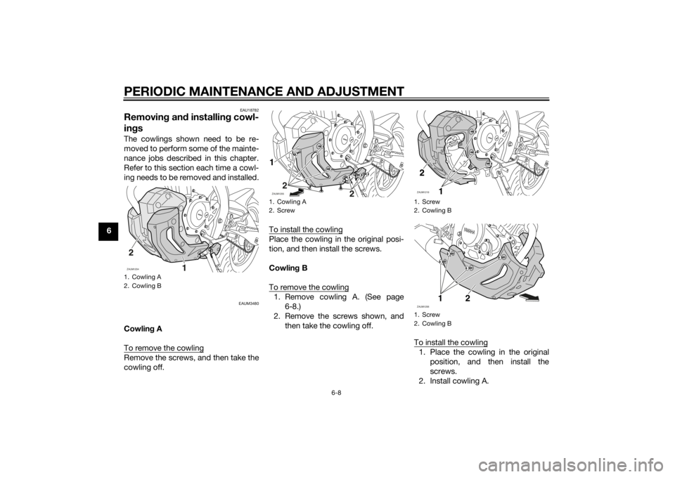
ingsThe cowlings shown need to be re-
moved to perform some of the mainte-
nance jobs described in this chapter.
Refer to this section each time a cowl-
ing needs to be removed and installed.
EAUM3480
Cowling A
To remove the cowlingRemove the screws, and then take the
cowling off.To install the cowling
Place the cowling in the original posi-
tion, and then install the screws.
Cowling B
To remove the cowling1. Remove cowling A. (See page
6-8.)
2. Remove the screws shown, and
then take the cowling off.
To install the cowling
1. Place the cowling in the original
position, and then install the
screws.
2. Install cowling A.
1. Cowling A
2. Cowling BZAUM1204
1. Cowling A
2. ScrewZAUM1205
2
1
1. Screw
2. Cowling B
1. Screw
2. Cowling BZAUM1219
FULL
LOW
1
ZAUM1206
YA M A H
A
12
U5D7E4E0.book Page 8 Thursday, July 10, 2014 3:01 PM
Page 58 of 96
PERIODIC MAINTENANCE AND ADJUSTMENT
6-16
6
EAU21402
Valve clearanceThe valve clearance changes with use,
resulting in improper air-fuel mixture
and/or engine noise. To prevent this
from occurring, the valve clearance
must be adjusted by a Yamaha dealer
at the intervals specified in the periodic
maintenance and lubrication chart.
EAUM2405
TiresTires are the only contact between the
vehicle and the road. Safety in all con-
ditions of riding depends on a relatively
small area of road contact. Therefore, it
is essential to maintain the tires in good
condition at all times and replace them
at the appropriate time with the speci-
fied tires.
Tire air pressure
The tire air pressure should be
checked and, if necessary, adjusted
before each ride.
WARNING
EWA10504
Operation of this vehicle with im-
proper tire pressure may cause se-
vere injury or death from loss of
control.
The tire air pressure must be
checked and adjusted on cold
tires (i.e., when the temperature
of the tires equals the ambient
temperature).
The tire air pressure must be
adjusted in accordance with the
riding speed and with the totalweight of rider, passenger, car-
go, and accessories approved
for this model.
WARNING
EWA10512
Never overload your vehicle. Opera-
tion of an overloaded vehicle could
cause an accident.Tire air pressure (measured on cold
tires):
0–90 kg (0–198 lb):
Front:
180 kPa (1.80 kgf/cm², 26 psi)
Rear:
200 kPa (2.00 kgf/cm², 29 psi)
MT125 90–180 kg (198–397 lb)
MT125A 90–178 kg (198–392 lb):
Front:
180 kPa (1.80 kgf/cm², 26 psi)
Rear:
225 kPa (2.25 kgf/cm², 33 psi)
Maximum load*:
MT125 180 kg (397 lb)
MT125A 178 kg (392 lb)
* Total weight of rider, passenger, car-
go and accessories
U5D7E4E0.book Page 16 Thursday, July 10, 2014 3:01 PM
Page 59 of 96
PERIODIC MAINTENANCE AND ADJUSTMENT
6-17
6 Tire inspection
The tires must be checked before each
ride. If the center tread depth reaches
the specified limit, if the tire has a nail
or glass fragments in it, or if the side-
wall is cracked, have a Yamaha dealer
replace the tire immediately.
TIPThe tire tread depth limits may differ
from country to country. Always com-
ply with the local regulations.
WARNING
EWA10472
Have a Yamaha dealer replace
excessively worn tires. Besides
being illegal, operating the vehi-
cle with excessively worn tires
decreases riding stability and
can lead to loss of control.
The replacement of all wheel
and brake-related parts, includ-
ing the tires, should be left to a
Yamaha dealer, who has the
necessary professional knowl-
edge and experience to do so.
Ride at moderate speeds after
changing a tire since the tire
surface must first be “broken
in” for it to develop its optimal
characteristics.
Tire information
This motorcycle is equipped with tube-
less tires, tire air valves and cast
wheels.
Tires age, even if they have not been
used or have only been used occasion-
ally. Cracking of the tread and sidewall
rubber, sometimes accompanied by
carcass deformation, is an evidence of
ageing. Old and aged tires shall be
checked by tire specialists to ascertain
their suitability for further use.
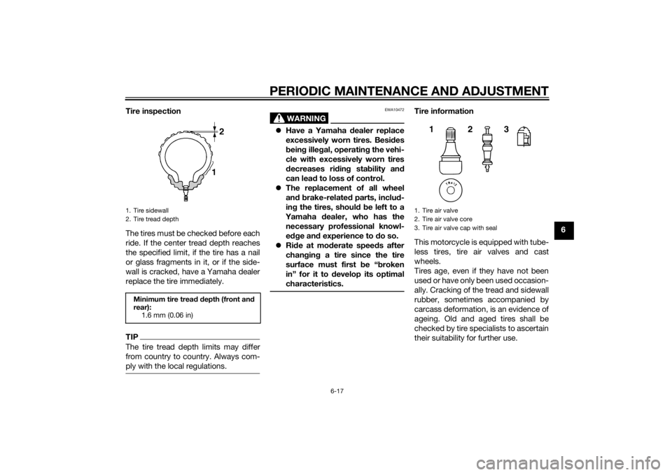
1. Tire sidewall
2. Tire tread depthMinimum tire tread depth (front and
rear):
1.6 mm (0.06 in)
1. Tire air valve
2. Tire air valve core
3. Tire air valve cap with seal
123
U5D7E4E0.book Page 17 Thursday, July 10, 2014 3:01 PM
Page 70 of 96
PERIODIC MAINTENANCE AND ADJUSTMENT
6-28
6
EAUM1653
Lubricating the swingarm piv-
otsThe swingarm pivots must be lubricat-
ed by a Yamaha dealer at the intervals
specified in the periodic maintenance
and lubrication chart.
EAU23273
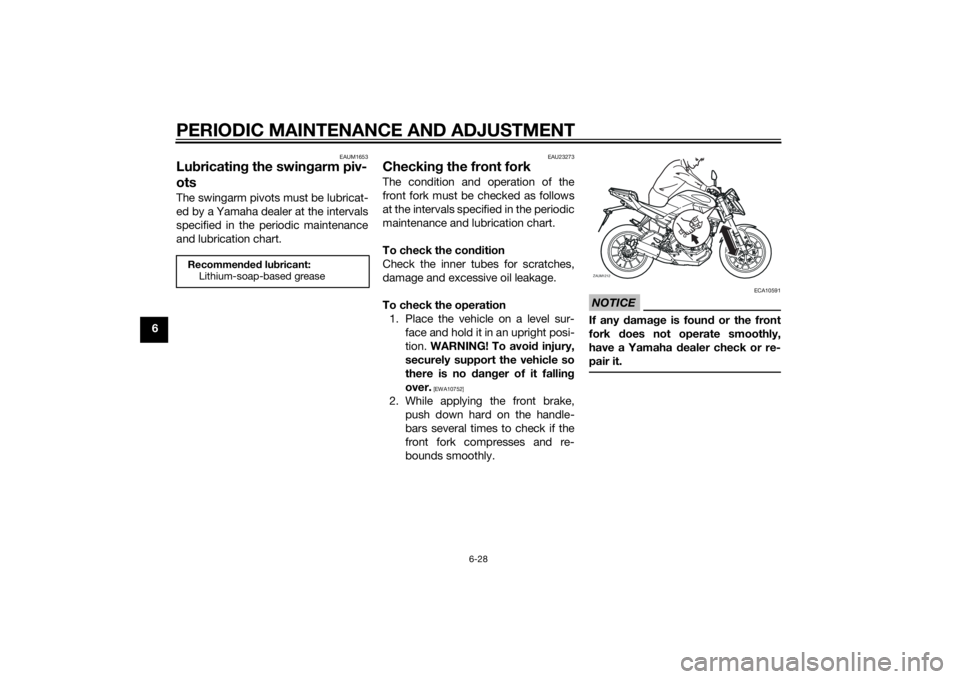
Checking the front forkThe condition and operation of the
front fork must be checked as follows
at the intervals specified in the periodic
maintenance and lubrication chart.
To check the condition
Check the inner tubes for scratches,
damage and excessive oil leakage.
To check the operation
1. Place the vehicle on a level sur-
face and hold it in an upright posi-
tion. WARNING! To avoid injury,
securely support the vehicle so
there is no danger of it falling
over.
[EWA10752]
2. While applying the front brake,
push down hard on the handle-
bars several times to check if the
front fork compresses and re-
bounds smoothly.
NOTICE
ECA10591
If any damage is found or the front
fork does not operate smoothly,
have a Yamaha dealer check or re-
pair it.
Recommended lubricant:
Lithium-soap-based grease
ZAUM1212
YA M A H A
U5D7E4E0.book Page 28 Thursday, July 10, 2014 3:01 PM
Page 79 of 96
PERIODIC MAINTENANCE AND ADJUSTMENT
6-37
6
2. Lift the front wheel off the ground
according to the procedure in the
previous section “Supporting the
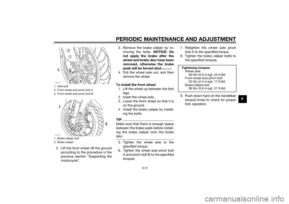
motorcycle”.3. Remove the brake caliper by re-
moving the bolts. NOTICE: Do
not apply the brake after the
wheel and brake disc have been
removed, otherwise the brake
pads will be forced shut.
[ECA11073]
4. Pull the wheel axle out, and then
remove the wheel.
To install the front wheel
1. Lift the wheel up between the fork
legs.
2. Insert the wheel axle.
3. Lower the front wheel so that it is
on the ground.
4. Install the brake caliper by install-
ing the bolts.TIPMake sure that there is enough space
between the brake pads before install-
ing the brake caliper onto the brake
disc.5. Tighten the wheel axle to the
specified torque.
6. Tighten the wheel axle pinch bolt
A and pinch bolt B to the specified
torques.7. Retighten the wheel axle pinch
bolt A to the specified torque.
8. Tighten the brake caliper bolts to
the specified torques.
9. Push down hard on the handlebar
several times to check for proper
fork operation.
1. Axle bolt
2. Front wheel axle pinch bolt A
3. Front wheel axle pinch bolt B
1. Brake caliper bolt
2. Brake caliperZAUM1215
3
ZAUM1192
Tightening torques:
Wheel axle:
59 Nm (5.9 m·kgf, 43 ft·lbf)
Front wheel axle pinch bolt:
23 Nm (2.3 m·kgf, 17 ft·lbf)
Brake caliper bolt:
38 Nm (3.8 m·kgf, 27 ft·lbf)
U5D7E4E0.book Page 37 Thursday, July 10, 2014 3:01 PM
Page 87 of 96
MOTORCYCLE CARE AND STORAGE7-3
7 4. To prevent corrosion, it is recom-
mended to apply a corrosion pro-
tection spray on all metal,
including chrome- and nickel-plat-
ed, surfaces.
5. Use spray oil as a universal clean-
er to remove any remaining dirt.
6. Touch up minor paint damage
caused by stones, etc.
7. Wax all painted surfaces.
8. Let the motorcycle dry completely
before storing or covering it.
WARNING
EWA11132
Contaminants on the brakes or tires
can cause loss of control.
Make sure that there is no oil or
wax on the brakes or tires.
If necessary, clean the brake
discs and brake linings with a
regular brake disc cleaner or
acetone, and wash the tires with
warm water and a mild deter-
gent. Before riding at higher
speeds, test the motorcycle’s
braking performance and cor-
nering behavior.
NOTICE
ECA10801
Apply spray oil and wax spar-
ingly and make sure to wipe off
any excess.
Never apply oil or wax to any
rubber and plastic parts, but
treat them with a suitable care
product.
Avoid using abrasive polishing
compounds as they will wear
away the paint.TIPConsult a Yamaha dealer for ad-
vice on what products to use.
Washing, rainy weather or humid
climates can cause the headlight
lens to fog. Turning the headlight
on for a short period of time will
help remove the moisture from the
lens.
EAU43203
StorageShort-term
Always store your motorcycle in a cool,
dry place and, if necessary, protect it
against dust with a porous cover. Be
sure the engine and the exhaust sys-
tem are cool before covering the mo-
torcycle.NOTICE
ECA10811
Storing the motorcycle in a
poorly ventilated room or cover-
ing it with a tarp, while it is still
wet, will allow water and humid-
ity to seep in and cause rust.
To prevent corrosion, avoid
damp cellars, stables (because
of the presence of ammonia)
and areas where strong chemi-
cals are stored.Long-term
Before storing your motorcycle for sev-
eral months:
1. Follow all the instructions in the
“Care” section of this chapter.
U5D7E4E0.book Page 3 Thursday, July 10, 2014 3:01 PM
Page 88 of 96

MOTORCYCLE CARE AND STORAGE
7-4
72. Fill up the fuel tank and add fuel
stabilizer (if available) to prevent
the fuel tank from rusting and the
fuel from deteriorating.
3. Perform the following steps to
protect the cylinder, piston rings,
etc. from corrosion.
a. Remove the spark plug cap
and spark plug.
b. Pour a teaspoonful of engine
oil into the spark plug bore.
c. Install the spark plug cap onto
the spark plug, and then place
the spark plug on the cylinder
head so that the electrodes are
grounded. (This will limit spark-
ing during the next step.)
d. Turn the engine over several
times with the starter. (This will
coat the cylinder wall with oil.)
e. Remove the spark plug cap
from the spark plug, and then
install the spark plug and the
spark plug cap. WARNING! To
prevent damage or injury
from sparking, make sure to
ground the spark plug elec-
trodes while turning the en-
gine over.
[EWA10952]
4. Lubricate all control cables and
the pivoting points of all levers and
pedals as well as of the side-
stand/centerstand.
5. Check and, if necessary, correct
the tire air pressure, and then lift
the motorcycle so that both of its
wheels are off the ground. Alterna-
tively, turn the wheels a little every
month in order to prevent the tires
from becoming degraded in one
spot.
6. Cover the muffler outlet with a
plastic bag to prevent moisture
from entering it.
7. Remove the battery and fully
charge it. Store it in a cool, dry
place and charge it once a month.
Do not store the battery in an ex-
cessively cold or warm place [less
than 0 °C (30 °F) or more than 30
°C (90 °F)]. For more information
on storing the battery, see page
6-30.TIPMake any necessary repairs before
storing the motorcycle.
U5D7E4E0.book Page 4 Thursday, July 10, 2014 3:01 PM