light YAMAHA MT-125 2015 Owner's Manual
[x] Cancel search | Manufacturer: YAMAHA, Model Year: 2015, Model line: MT-125, Model: YAMAHA MT-125 2015Pages: 96, PDF Size: 7.28 MB
Page 51 of 96
PERIODIC MAINTENANCE AND ADJUSTMENT
6-9
6
EAU19605
Checking the spark plugThe spark plug is an important engine
component, which is easy to check.
Since heat and deposits will cause any
spark plug to slowly erode, the spark
plug should be removed and checked
in accordance with the periodic main-
tenance and lubrication chart. In addi-
tion, the condition of the spark plug
can reveal the condition of the engine.
To remove the spark plug
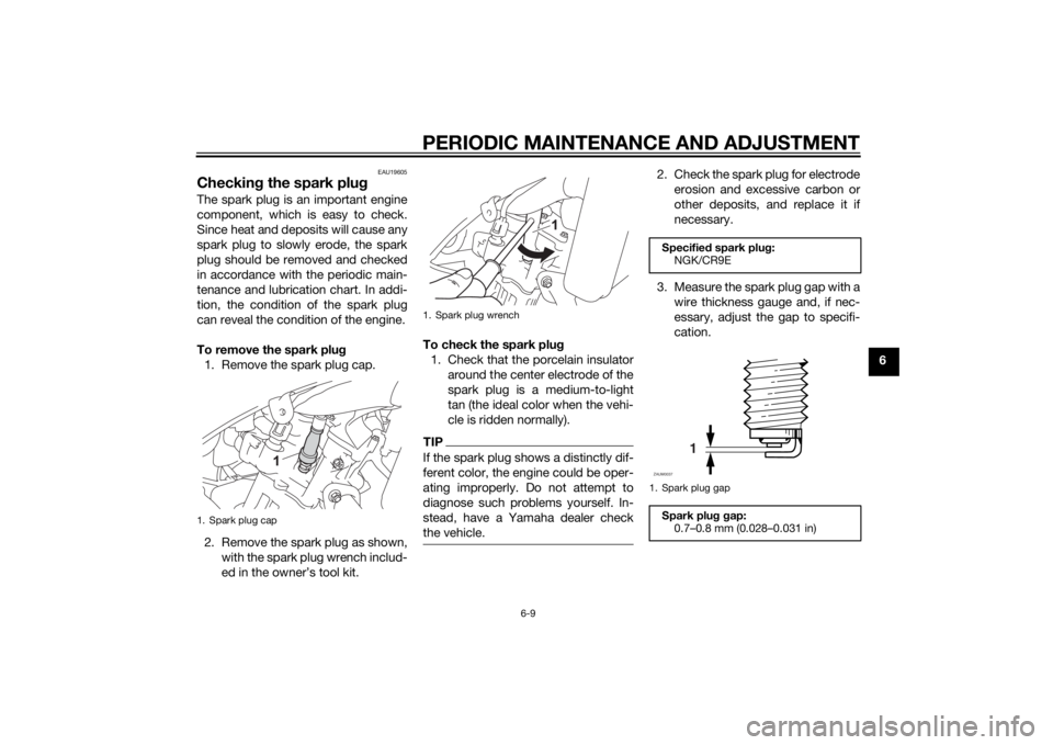
1. Remove the spark plug cap.
2. Remove the spark plug as shown,
with the spark plug wrench includ-
ed in the owner’s tool kit.To check the spark plug
1. Check that the porcelain insulator
around the center electrode of the
spark plug is a medium-to-light
tan (the ideal color when the vehi-
cle is ridden normally).
TIPIf the spark plug shows a distinctly dif-
ferent color, the engine could be oper-
ating improperly. Do not attempt to
diagnose such problems yourself. In-
stead, have a Yamaha dealer check
the vehicle.
2. Check the spark plug for electrode
erosion and excessive carbon or
other deposits, and replace it if
necessary.
3. Measure the spark plug gap with a
wire thickness gauge and, if nec-
essary, adjust the gap to specifi-
cation.
1. Spark plug cap
1. Spark plug wrench
Specified spark plug:
NGK/CR9E
1. Spark plug gap
Spark plug gap:
0.7–0.8 mm (0.028–0.031 in)
1
ZAUM0037
U5D7E4E0.book Page 9 Thursday, July 10, 2014 3:01 PM
Page 52 of 96
PERIODIC MAINTENANCE AND ADJUSTMENT
6-10
6To install the spark plug
1. Clean the surface of the spark
plug gasket and its mating sur-
face, and then wipe off any grime
from the spark plug threads.
2. Install the spark plug with the
spark plug wrench, and then tight-
en it to the specified torque.
TIPIf a torque wrench is not available
when installing a spark plug, a good
estimate of the correct torque is 1/4–
1/2 turn past finger tight. However, the
spark plug should be tightened to the
specified torque as soon as possible.3. Install the spark plug cap.
EAUM3490
Engine oil and oil filter ele-
mentThe engine oil level should be checked
before each ride. In addition, the oil
must be changed and the oil filter ele-
ment replaced at the intervals specified
in the periodic maintenance and lubri-
cation chart.
To check the engine oil level
1. Place the vehicle on a level sur-
face and hold it in an upright posi-
tion. A slight tilt to the side can
result in a false reading.
2. Start the engine, warm it up for
several minutes, and then turn it
off.
3. Wait a few minutes until the oil set-
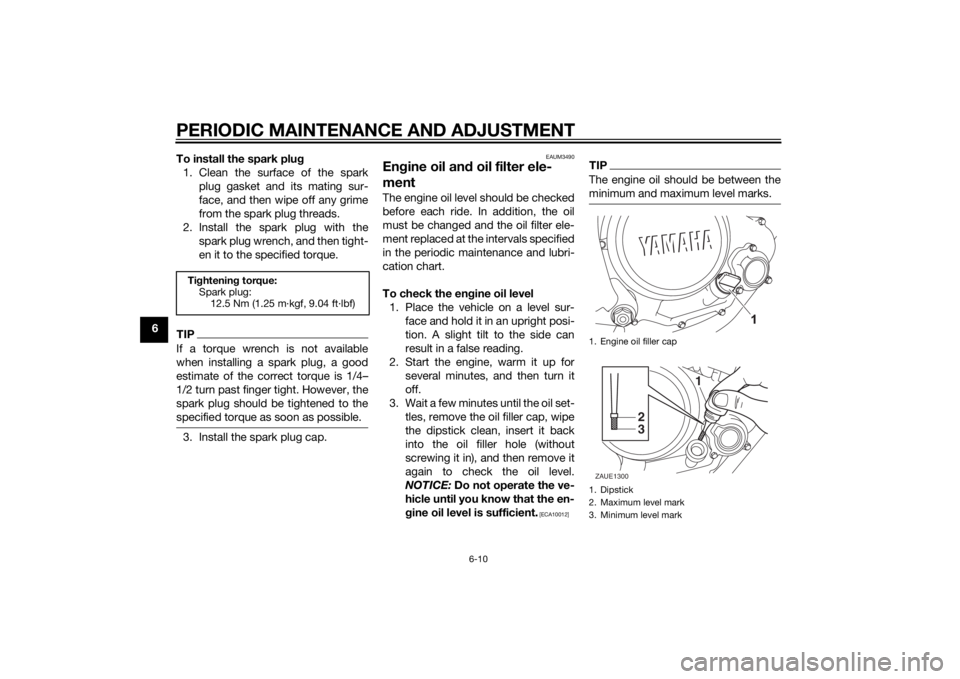
tles, remove the oil filler cap, wipe
the dipstick clean, insert it back
into the oil filler hole (without
screwing it in), and then remove it
again to check the oil level.
NOTICE: Do not operate the ve-
hicle until you know that the en-
gine oil level is sufficient.
[ECA10012]
TIPThe engine oil should be between the
minimum and maximum level marks.
Tightening torque:
Spark plug:
12.5 Nm (1.25 m·kgf, 9.04 ft·lbf)
1. Engine oil filler cap
1. Dipstick
2. Maximum level mark
3. Minimum level mark
1
2
3
ZAUE1300
U5D7E4E0.book Page 10 Thursday, July 10, 2014 3:01 PM
Page 55 of 96
PERIODIC MAINTENANCE AND ADJUSTMENT
6-13
6 12. Start the engine, and then let it idle
for several minutes while checking
it for oil leakage. If oil is leaking,
immediately turn the engine off
and check for the cause.
13. Turn the engine off, and then
check the oil level and correct it if
necessary.
14. Reset the oil change indicator.
(See page 3-10.)
EAU20071
CoolantThe coolant level should be checked
before each ride. In addition, the cool-
ant must be changed at the intervals
specified in the periodic maintenance
and lubrication chart.
EAUM1726
To check the coolant level
1. Place the vehicle on a level sur-
face and hold it in an upright posi-
tion.TIPThe coolant level must be
checked on a cold engine since
the level varies with engine tem-
perature.
Make sure that the vehicle is posi-
tioned straight up when checking
the coolant level. A slight tilt to the
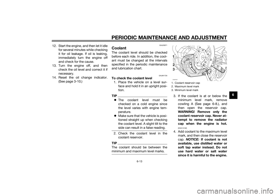
side can result in a false reading.2. Check the coolant level in the
coolant reservoir.TIPThe coolant should be between the
minimum and maximum level marks.
3. If the coolant is at or below the
minimum level mark, remove
cowling A (See page 6-8.), and
then open the reservoir cap.
WARNING! Remove only the
coolant reservoir cap. Never at-
tempt to remove the radiator
cap when the engine is hot.
[EWA15162]
4. Add coolant to the maximum level
mark, and then close the reservoir
cap. NOTICE: If coolant is not
available, use distilled water or
soft tap water instead. Do not
use hard water or salt water
since it is harmful to the engine.1. Coolant reservoir cap
2. Maximum level mark
3. Minimum level markZAUM1207
FULL
LOW
2
3
U5D7E4E0.book Page 13 Thursday, July 10, 2014 3:01 PM
Page 63 of 96
PERIODIC MAINTENANCE AND ADJUSTMENT
6-21
6
EAUM3541
Brake light switchesFor ABS models
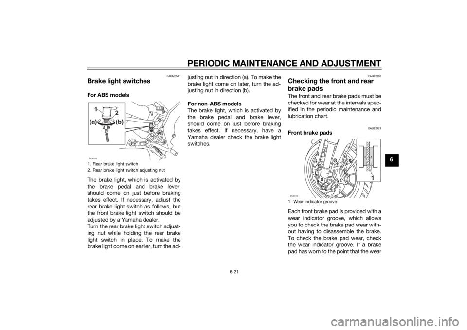
The brake light, which is activated by
the brake pedal and brake lever,
should come on just before braking
takes effect. If necessary, adjust the
rear brake light switch as follows, but
the front brake light switch should be
adjusted by a Yamaha dealer.
Turn the rear brake light switch adjust-
ing nut while holding the rear brake
light switch in place. To make the
brake light come on earlier, turn the ad-justing nut in direction (a). To make the
brake light come on later, turn the ad-
justing nut in direction (b).
For non-ABS models
The brake light, which is activated by
the brake pedal and brake lever,
should come on just before braking
takes effect. If necessary, have a
Yamaha dealer check the brake light
switches.
EAU22393
Checking the front and rear
brake padsThe front and rear brake pads must be
checked for wear at the intervals spec-
ified in the periodic maintenance and
lubrication chart.
EAU22421
Front brake pads
Each front brake pad is provided with a
wear indicator groove, which allows
you to check the brake pad wear with-
out having to disassemble the brake.
To check the brake pad wear, check
the wear indicator groove. If a brake
pad has worn to the point that the wear
1. Rear brake light switch
2. Rear brake light switch adjusting nutZAUM1230
2
(a)(b)
1. Wear indicator grooveZAUM1180
1
U5D7E4E0.book Page 21 Thursday, July 10, 2014 3:01 PM
Page 74 of 96
PERIODIC MAINTENANCE AND ADJUSTMENT
6-32
6
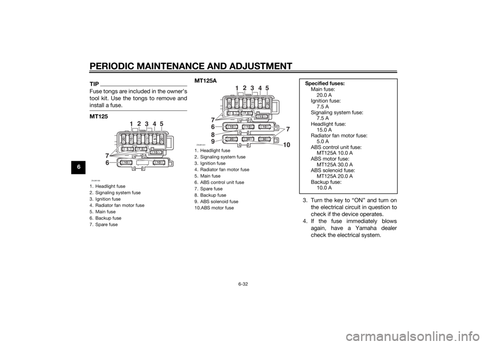
TIPFuse tongs are included in the owner’s
tool kit. Use the tongs to remove and
install a fuse.MT125MT125A
3. Turn the key to “ON” and turn on
the electrical circuit in question to
check if the device operates.
4. If the fuse immediately blows
again, have a Yamaha dealer
check the electrical system.1. Headlight fuse
2. Signaling system fuse
3. Ignition fuse
4. Radiator fan motor fuse
5. Main fuse
6. Backup fuse
7. Spare fuseZAUM1189
10
10
15
7.5
5
20
7.5 7.5
15 20
5
7
1
2
3
45
6
1. Headlight fuse
2. Signaling system fuse
3. Ignition fuse
4. Radiator fan motor fuse
5. Main fuse
6. ABS control unit fuse
7. Spare fuse
8. Backup fuse
9. ABS solenoid fuse
10.ABS motor fuseZAUM1231
1030
30
20
7
8
9
10
10
15
7.5
20
7.5 7.5
15
5 20
5
7
1
2
3
45
6
Specified fuses:
Main fuse:
20.0 A
Ignition fuse:
7.5 A
Signaling system fuse:
7.5 A
Headlight fuse:
15.0 A
Radiator fan motor fuse:
5.0 A
ABS control unit fuse:
MT125A 10.0 A
ABS motor fuse:
MT125A 30.0 A
ABS solenoid fuse:
MT125A 20.0 A
Backup fuse:
10.0 A
U5D7E4E0.book Page 32 Thursday, July 10, 2014 3:01 PM
Page 75 of 96
PERIODIC MAINTENANCE AND ADJUSTMENT
6-33
6
EAUM3501
Replacing the headlight bulbThis model is equipped with a halogen
bulb headlight. If the headlight bulb
burns out, replace it as follows.NOTICE
ECA10651
Take care not to damage the follow-
ing parts:
Headlight bulb
Do not touch the glass part of
the headlight bulb to keep it free
from oil, otherwise the transpar-
ency of the glass, the luminosity
of the bulb, and the bulb life will
be adversely affected. Thor-
oughly clean off any dirt and fin-
gerprints on the headlight bulb
using a cloth moistened with al-
cohol or thinner.
Headlight lens
Do not affix any type of tinted
film or stickers to the headlight
lens.
Do not use a headlight bulb of a
wattage higher than specified.
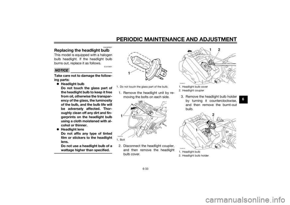
1. Remove the headlight unit by re-
moving the bolts on each side.
2. Disconnect the headlight coupler,
and then remove the headlight
bulb cover.3. Remove the headlight bulb holder
by turning it counterclockwise,
and then remove the burnt-out
bulb.1. Do not touch the glass part of the bulb.
1. BoltZAUM12201
1. Headlight bulb cover
2. Headlight coupler
1. Headlight bulb
2. Headlight bulb holderZAUM1221
2
1
ZAUM1222
2
1
U5D7E4E0.book Page 33 Thursday, July 10, 2014 3:01 PM
Page 76 of 96
PERIODIC MAINTENANCE AND ADJUSTMENT
6-34
64. Place a new headlight bulb into
position, and then secure it with
the bulb holder.
5. Install the headlight bulb cover,
and then connect the coupler.
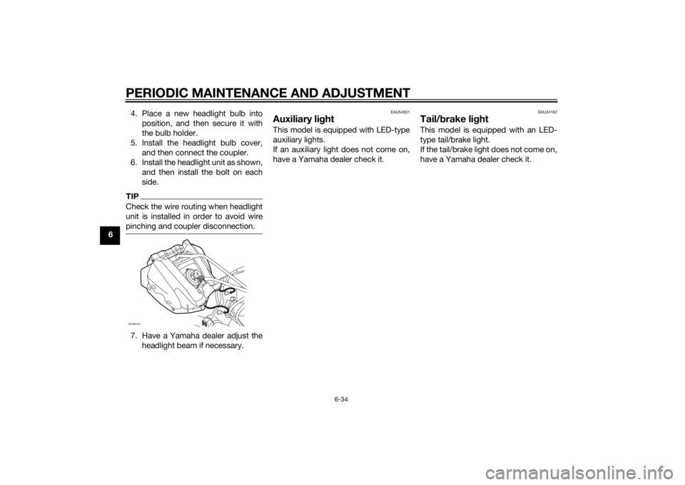
6. Install the headlight unit as shown,
and then install the bolt on each
side.
TIPCheck the wire routing when headlight
unit is installed in order to avoid wire
pinching and coupler disconnection.7. Have a Yamaha dealer adjust the
headlight beam if necessary.
EAU54501
Auxiliary lightThis model is equipped with LED-type
auxiliary lights.
If an auxiliary light does not come on,
have a Yamaha dealer check it.
EAU24182
Tail/brake lightThis model is equipped with an LED-
type tail/brake light.
If the tail/brake light does not come on,
have a Yamaha dealer check it.
ZAUM1224
U5D7E4E0.book Page 34 Thursday, July 10, 2014 3:01 PM
Page 77 of 96
PERIODIC MAINTENANCE AND ADJUSTMENT
6-35
6
EAU24205
Replacing a turn signal light
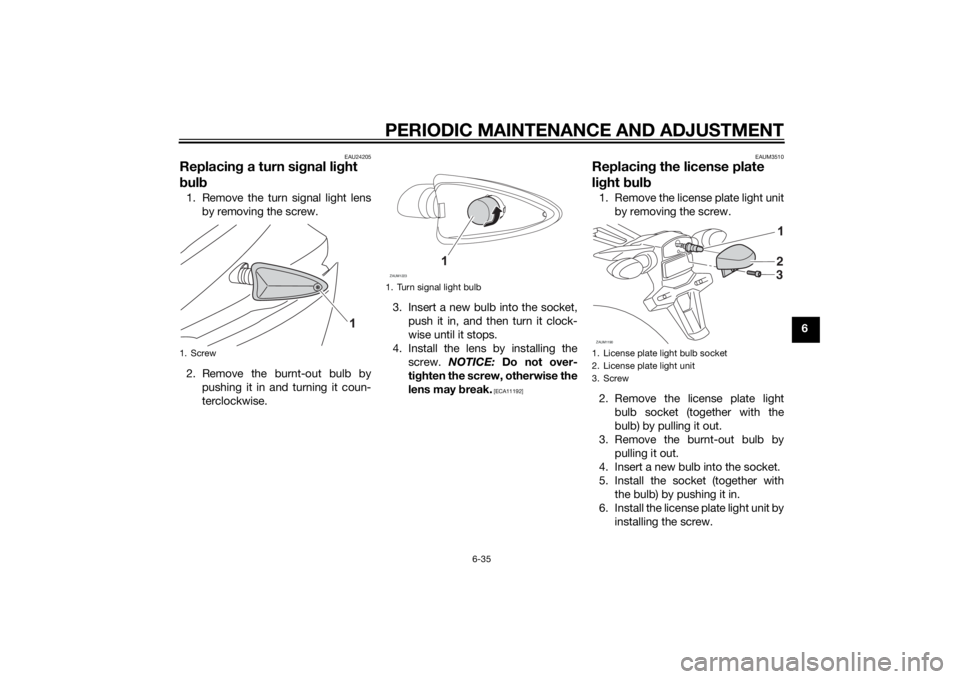
bulb1. Remove the turn signal light lens
by removing the screw.
2. Remove the burnt-out bulb by
pushing it in and turning it coun-
terclockwise.3. Insert a new bulb into the socket,
push it in, and then turn it clock-
wise until it stops.
4. Install the lens by installing the
screw. NOTICE: Do not over-
tighten the screw, otherwise the
lens may break.
[ECA11192]EAUM3510
Replacing the license plate
light bulb1. Remove the license plate light unit
by removing the screw.
2. Remove the license plate light
bulb socket (together with the
bulb) by pulling it out.
3. Remove the burnt-out bulb by
pulling it out.
4. Insert a new bulb into the socket.
5. Install the socket (together with
the bulb) by pushing it in.
6. Install the license plate light unit by
installing the screw.
1. Screw
1. Turn signal light bulbZAUM1223
1. License plate light bulb socket
2. License plate light unit
3. ScrewZAUM1190
2
3
U5D7E4E0.book Page 35 Thursday, July 10, 2014 3:01 PM
Page 82 of 96
PERIODIC MAINTENANCE AND ADJUSTMENT
6-40
6
EAU25872
TroubleshootingAlthough Yamaha motorcycles receive
a thorough inspection before shipment
from the factory, trouble may occur
during operation. Any problem in the
fuel, compression, or ignition systems,
for example, can cause poor starting
and loss of power.
The following troubleshooting charts
represent quick and easy procedures
for checking these vital systems your-
self. However, should your motorcycle
require any repair, take it to a Yamaha
dealer, whose skilled technicians have
the necessary tools, experience, and
know-how to service the motorcycle
properly.
Use only genuine Yamaha replace-
ment parts. Imitation parts may look
like Yamaha parts, but they are often
inferior, have a shorter service life and
can lead to expensive repair bills.
WARNING
EWA15142
When checking the fuel system, do
not smoke, and make sure there are
no open flames or sparks in the ar-
ea, including pilot lights from waterheaters or furnaces. Gasoline or
gasoline vapors can ignite or ex-
plode, causing severe injury or prop-
erty damage.U5D7E4E0.book Page 40 Thursday, July 10, 2014 3:01 PM
Page 85 of 96
MOTORCYCLE CARE AND STORAGE7-1
7
EAU37834
Matte color cautionNOTICE
ECA15193
Some models are equipped with
matte colored finished parts. Be
sure to consult a Yamaha dealer for
advice on what products to use be-
fore cleaning the vehicle. Using a
brush, harsh chemical products or
cleaning compounds when cleaning
these parts will scratch or damage
their surface. Wax also should not
be applied to any matte colored fin-
ished parts.
EAUM2453
CareWhile the open design of a motorcycle
reveals the attractiveness of the tech-
nology, it also makes it more vulnera-
ble. Rust and corrosion can develop
even if high-quality components are
used. A rusty exhaust pipe may go un-
noticed on a car, however, it detracts
from the overall appearance of a mo-
torcycle. Frequent and proper care
does not only comply with the terms of
the warranty, but it will also keep your
motorcycle looking good, extend its
life and optimize its performance.
Before cleaning
1. Cover the muffler outlet with a
plastic bag after the engine has
cooled down.
2. Make sure that all caps and cov-
ers as well as all electrical cou-
plers and connectors, including
the spark plug cap, are tightly in-
stalled.
3. Remove extremely stubborn dirt,
like oil burnt onto the crankcase,
with a degreasing agent and a
brush, but never apply such prod-ucts onto seals, gaskets, sprock-
ets, the drive chain and wheel
axles. Always rinse the dirt and
degreaser off with water.
Cleaning
NOTICE
ECA10773
Avoid using strong acidic wheel
cleaners, especially on spoked
wheels. If such products are
used on hard-to-remove dirt, do
not leave the cleaner on the af-
fected area any longer than in-
structed. Also, thoroughly rinse
the area off with water, immedi-
ately dry it, and then apply a cor-
rosion protection spray.
Improper cleaning can damage
plastic parts (such as cowlings,
panels, windshields, headlight
lenses, meter lenses, etc.) and
the mufflers. Use only a soft,
clean cloth or sponge with wa-
ter to clean plastic. However, if
the plastic parts cannot be thor-
oughly cleaned with water, di-
luted mild detergent with water
may be used. Be sure to rinse
U5D7E4E0.book Page 1 Thursday, July 10, 2014 3:01 PM