valve YAMAHA MT-125 2015 Owners Manual
[x] Cancel search | Manufacturer: YAMAHA, Model Year: 2015, Model line: MT-125, Model: YAMAHA MT-125 2015Pages: 96, PDF Size: 7.28 MB
Page 6 of 96

TABLE OF CONTENTSSAFETY INFORMATION.................. 1-1
DESCRIPTION.................................. 2-1
Left view ......................................... 2-1
Right view ....................................... 2-2
Controls and instruments ............... 2-3
INSTRUMENT AND CONTROL
FUNCTIONS...................................... 3-1
Main switch/steering lock............... 3-1
Indicator lights and warning
lights............................................ 3-2
Multi-function meter unit ................ 3-4
Handlebar switches ...................... 3-11
Clutch lever .................................. 3-13
Shift pedal .................................... 3-13
Brake lever.................................... 3-13
Brake pedal .................................. 3-14
ABS (for ABS models) .................. 3-14
Fuel tank cap ................................ 3-15
Fuel ............................................... 3-16
Catalytic converter ....................... 3-17
Rider seat ..................................... 3-18
Sidestand ..................................... 3-18
Ignition circuit cut-off system ....... 3-19FOR YOUR SAFETY –
PRE-OPERATION CHECKS............. 4-1
OPERATION AND IMPORTANT
RIDING POINTS................................ 5-1
Starting the engine .......................... 5-1
Shifting ............................................ 5-2
Tips for reducing fuel
consumption ................................ 5-3
Engine break-in ............................... 5-3
Parking ............................................ 5-4
PERIODIC MAINTENANCE AND
ADJUSTMENT................................... 6-1
Owner’s tool kit ............................... 6-2
Periodic maintenance chart for the
emission control system .............. 6-3
General maintenance and
lubrication chart ........................... 6-4
Removing and installing cowlings... 6-8
Checking the spark plug ................. 6-9
Engine oil and oil filter element ..... 6-10
Coolant.......................................... 6-13
Replacing the air filter element
and cleaning the check hose..... 6-14
Checking the engine idling
speed ......................................... 6-15
Adjusting the throttle grip free
play ............................................ 6-15
Valve clearance ............................. 6-16
Tires .............................................. 6-16Cast wheels .................................. 6-19
Adjusting the clutch lever free
play ............................................ 6-19
Checking the front brake lever
free play..................................... 6-20
Adjusting the brake pedal free
play ............................................ 6-20
Brake light switches ..................... 6-21
Checking the front and rear brake
pads .......................................... 6-21
Checking the brake fluid level ...... 6-22
Changing the brake fluid .............. 6-23
Drive chain slack........................... 6-24
Cleaning and lubricating the drive
chain.......................................... 6-25
Checking and lubricating the
cables ........................................ 6-26
Checking and lubricating the
throttle grip and cable ............... 6-26
Checking and lubricating the
brake and clutch levers ............. 6-26
Checking and lubricating the
brake pedal ............................... 6-27
Checking and lubricating the
sidestand................................... 6-27
Lubricating the swingarm
pivots......................................... 6-28
Checking the front fork ................. 6-28
Checking the steering................... 6-29
Checking the wheel bearings ....... 6-29
Battery .......................................... 6-30U5D7E4E0.book Page 1 Thursday, July 10, 2014 3:01 PM
Page 31 of 96
INSTRUMENT AND CONTROL FUNCTIONS
3-16
3
EAU13213
FuelMake sure there is sufficient gasoline in
the tank.
WARNING
EWA10882
Gasoline and gasoline vapors are
extremely flammable. To avoid fires
and explosions and to reduce the
risk of injury when refueling, follow
these instructions.1. Before refueling, turn off the en-
gine and be sure that no one is sit-
ting on the vehicle. Never refuel
while smoking, or while in the vi-
cinity of sparks, open flames, or
other sources of ignition such as
the pilot lights of water heaters
and clothes dryers.
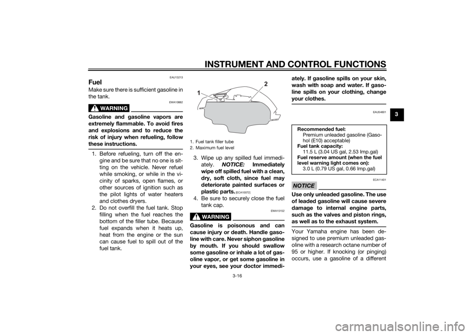
2. Do not overfill the fuel tank. Stop
filling when the fuel reaches the
bottom of the filler tube. Because
fuel expands when it heats up,
heat from the engine or the sun
can cause fuel to spill out of the
fuel tank.3. Wipe up any spilled fuel immedi-
ately. NOTICE: Immediately
wipe off spilled fuel with a clean,
dry, soft cloth, since fuel may
deteriorate painted surfaces or
plastic parts.
[ECA10072]
4. Be sure to securely close the fuel
tank cap.
WARNING
EWA15152
Gasoline is poisonous and can
cause injury or death. Handle gaso-
line with care. Never siphon gasoline
by mouth. If you should swallow
some gasoline or inhale a lot of gas-
oline vapor, or get some gasoline in
your eyes, see your doctor immedi-ately. If gasoline spills on your skin,
wash with soap and water. If gaso-
line spills on your clothing, change
your clothes.
EAU54601
NOTICE
ECA11401
Use only unleaded gasoline. The use
of leaded gasoline will cause severe
damage to internal engine parts,
such as the valves and piston rings,
as well as to the exhaust system.Your Yamaha engine has been de-
signed to use premium unleaded gas-
oline with a research octane number of
95 or higher. If knocking (or pinging)
occurs, use a gasoline of a different
1. Fuel tank filler tube
2. Maximum fuel level
Recommended fuel:
Premium unleaded gasoline (Gaso-
hol (E10) acceptable)
Fuel tank capacity:
11.5 L (3.04 US gal, 2.53 Imp.gal)
Fuel reserve amount (when the fuel
level warning light comes on):
3.0 L (0.79 US gal, 0.66 Imp.gal)
U5D7E4E0.book Page 16 Thursday, July 10, 2014 3:01 PM
Page 45 of 96
PERIODIC MAINTENANCE AND ADJUSTMENT
6-3
6
EAU46872
TIPThe annual checks must be performed every year, except if a kilometer-based maintenance, or for the UK, a
mileage-based maintenance, is performed instead.
From 30000 km (17500 mi), repeat the maintenance intervals starting from 6000 km (3500 mi).
Items marked with an asterisk should be performed by a Yamaha dealer as they require special tools, data and tech-
nical skills.
EAU46921
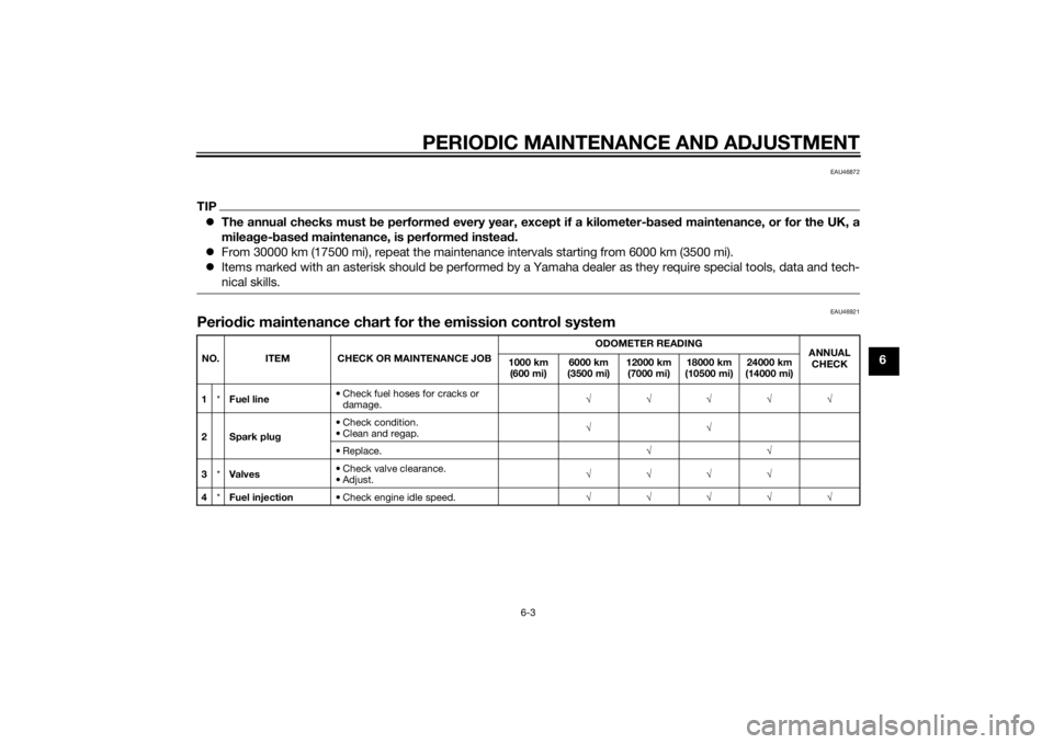
Periodic maintenance chart for the emission control systemNO. ITEM CHECK OR MAINTENANCE JOBODOMETER READING
ANNUAL
CHECK 1000 km
(600 mi)6000 km
(3500 mi)12000 km
(7000 mi)18000 km
(10500 mi)24000 km
(14000 mi)
1*Fuel line• Check fuel hoses for cracks or
damage.√√√√√
2 Spark plug• Check condition.
• Clean and regap.√√
•Replace.√√
3*Valves• Check valve clearance.
•Adjust.√√√√
4*Fuel injection• Check engine idle speed.√√√√√
U5D7E4E0.book Page 3 Thursday, July 10, 2014 3:01 PM
Page 58 of 96
PERIODIC MAINTENANCE AND ADJUSTMENT
6-16
6
EAU21402
Valve clearanceThe valve clearance changes with use,
resulting in improper air-fuel mixture
and/or engine noise. To prevent this
from occurring, the valve clearance
must be adjusted by a Yamaha dealer
at the intervals specified in the periodic
maintenance and lubrication chart.
EAUM2405
TiresTires are the only contact between the
vehicle and the road. Safety in all con-
ditions of riding depends on a relatively
small area of road contact. Therefore, it
is essential to maintain the tires in good
condition at all times and replace them
at the appropriate time with the speci-
fied tires.
Tire air pressure
The tire air pressure should be
checked and, if necessary, adjusted
before each ride.
WARNING
EWA10504
Operation of this vehicle with im-
proper tire pressure may cause se-
vere injury or death from loss of
control.
The tire air pressure must be
checked and adjusted on cold
tires (i.e., when the temperature
of the tires equals the ambient
temperature).
The tire air pressure must be
adjusted in accordance with the
riding speed and with the totalweight of rider, passenger, car-
go, and accessories approved
for this model.
WARNING
EWA10512
Never overload your vehicle. Opera-
tion of an overloaded vehicle could
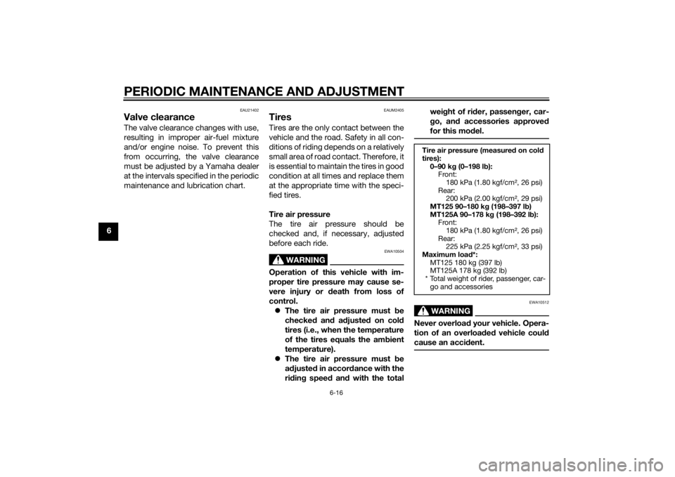
cause an accident.Tire air pressure (measured on cold
tires):
0–90 kg (0–198 lb):
Front:
180 kPa (1.80 kgf/cm², 26 psi)
Rear:
200 kPa (2.00 kgf/cm², 29 psi)
MT125 90–180 kg (198–397 lb)
MT125A 90–178 kg (198–392 lb):
Front:
180 kPa (1.80 kgf/cm², 26 psi)
Rear:
225 kPa (2.25 kgf/cm², 33 psi)
Maximum load*:
MT125 180 kg (397 lb)
MT125A 178 kg (392 lb)
* Total weight of rider, passenger, car-
go and accessories
U5D7E4E0.book Page 16 Thursday, July 10, 2014 3:01 PM
Page 59 of 96
PERIODIC MAINTENANCE AND ADJUSTMENT
6-17
6 Tire inspection
The tires must be checked before each
ride. If the center tread depth reaches
the specified limit, if the tire has a nail
or glass fragments in it, or if the side-
wall is cracked, have a Yamaha dealer
replace the tire immediately.
TIPThe tire tread depth limits may differ
from country to country. Always com-
ply with the local regulations.
WARNING
EWA10472
Have a Yamaha dealer replace
excessively worn tires. Besides
being illegal, operating the vehi-
cle with excessively worn tires
decreases riding stability and
can lead to loss of control.
The replacement of all wheel
and brake-related parts, includ-
ing the tires, should be left to a
Yamaha dealer, who has the
necessary professional knowl-
edge and experience to do so.
Ride at moderate speeds after
changing a tire since the tire
surface must first be “broken
in” for it to develop its optimal
characteristics.
Tire information
This motorcycle is equipped with tube-
less tires, tire air valves and cast
wheels.
Tires age, even if they have not been
used or have only been used occasion-
ally. Cracking of the tread and sidewall
rubber, sometimes accompanied by
carcass deformation, is an evidence of
ageing. Old and aged tires shall be
checked by tire specialists to ascertain
their suitability for further use.
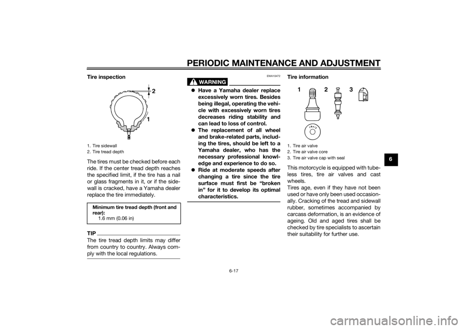
1. Tire sidewall
2. Tire tread depthMinimum tire tread depth (front and
rear):
1.6 mm (0.06 in)
1. Tire air valve
2. Tire air valve core
3. Tire air valve cap with seal
123
U5D7E4E0.book Page 17 Thursday, July 10, 2014 3:01 PM
Page 60 of 96
PERIODIC MAINTENANCE AND ADJUSTMENT
6-18
6
WARNING
EWA10902
The front and rear tires should
be of the same make and de-
sign, otherwise the handling
characteristics of the motorcy-
cle may be different, which
could lead to an accident.
Always make sure that the valve
caps are securely installed to
prevent air pressure leakage.
Use only the tire valves and
valve cores listed below to
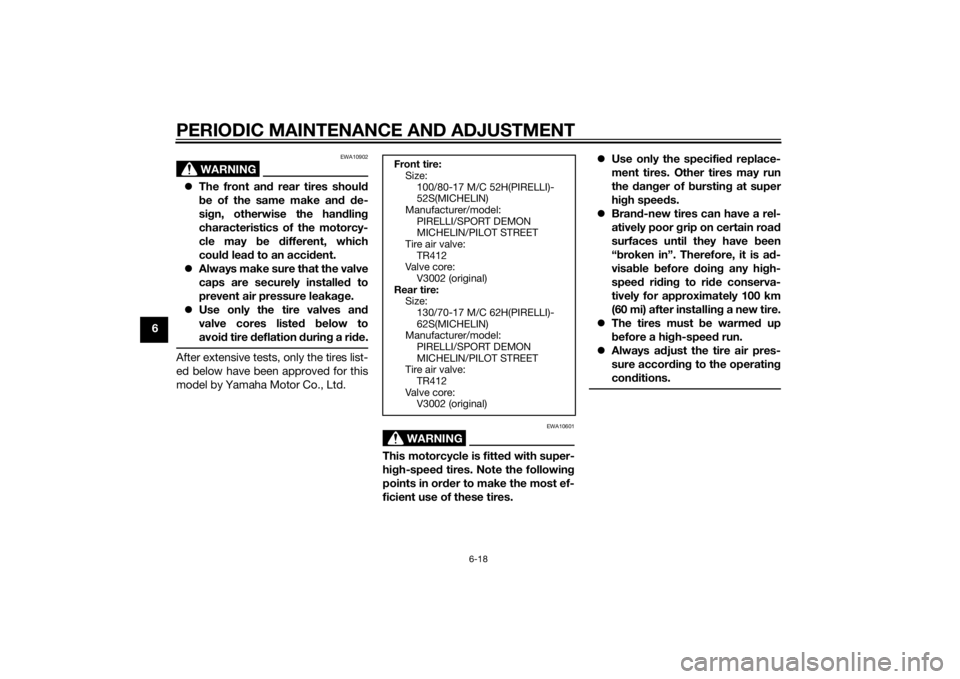
avoid tire deflation during a ride.After extensive tests, only the tires list-
ed below have been approved for this
model by Yamaha Motor Co., Ltd.
WARNING
EWA10601
This motorcycle is fitted with super-
high-speed tires. Note the following
points in order to make the most ef-
ficient use of these tires.Use only the specified replace-
ment tires. Other tires may run
the danger of bursting at super
high speeds.
Brand-new tires can have a rel-
atively poor grip on certain road
surfaces until they have been
“broken in”. Therefore, it is ad-
visable before doing any high-
speed riding to ride conserva-
tively for approximately 100 km
(60 mi) after installing a new tire.
The tires must be warmed up
before a high-speed run.
Always adjust the tire air pres-
sure according to the operating
conditions.Front tire:
Size:
100/80-17 M/C 52H(PIRELLI)-
52S(MICHELIN)
Manufacturer/model:
PIRELLI/SPORT DEMON
MICHELIN/PILOT STREET
Tire air valve:
TR412
Valve core:
V3002 (original)
Rear tire:
Size:
130/70-17 M/C 62H(PIRELLI)-
62S(MICHELIN)
Manufacturer/model:
PIRELLI/SPORT DEMON
MICHELIN/PILOT STREET
Tire air valve:
TR412
Valve core:
V3002 (original)
U5D7E4E0.book Page 18 Thursday, July 10, 2014 3:01 PM
Page 65 of 96
PERIODIC MAINTENANCE AND ADJUSTMENT
6-23
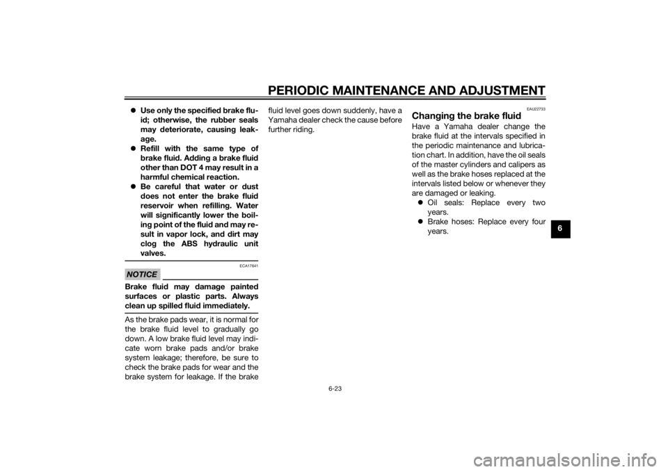
6 Use only the specified brake flu-
id; otherwise, the rubber seals
may deteriorate, causing leak-
age.
Refill with the same type of
brake fluid. Adding a brake fluid
other than DOT 4 may result in a
harmful chemical reaction.
Be careful that water or dust
does not enter the brake fluid
reservoir when refilling. Water
will significantly lower the boil-
ing point of the fluid and may re-
sult in vapor lock, and dirt may
clog the ABS hydraulic unit
valves.
NOTICE
ECA17641
Brake fluid may damage painted
surfaces or plastic parts. Always
clean up spilled fluid immediately.As the brake pads wear, it is normal for
the brake fluid level to gradually go
down. A low brake fluid level may indi-
cate worn brake pads and/or brake
system leakage; therefore, be sure to
check the brake pads for wear and the
brake system for leakage. If the brakefluid level goes down suddenly, have a
Yamaha dealer check the cause before
further riding.
EAU22733
Changing the brake fluidHave a Yamaha dealer change the
brake fluid at the intervals specified in
the periodic maintenance and lubrica-
tion chart. In addition, have the oil seals
of the master cylinders and calipers as
well as the brake hoses replaced at the
intervals listed below or whenever they
are damaged or leaking.
Oil seals: Replace every two
years.
Brake hoses: Replace every four
years.
U5D7E4E0.book Page 23 Thursday, July 10, 2014 3:01 PM
Page 93 of 96

10-1
10
INDEX
AABS (for ABS models) .......................... 3-14
ABS warning light (for ABS models) ....... 3-3
Air filter element and check hose,
replacing and cleaning ....................... 6-14
Auxiliary light ........................................ 6-34BBattery .................................................. 6-30
Brake and clutch levers, checking and
lubricating........................................... 6-26
Brake fluid, changing............................ 6-23
Brake fluid level, checking.................... 6-22
Brake lever............................................ 3-13
Brake light switches ............................. 6-21
Brake pedal .......................................... 3-14
Brake pedal, checking and
lubricating........................................... 6-27
Brake pedal free play, adjusting ........... 6-20CCables, checking and lubricating ......... 6-26
Care ........................................................ 7-1
Catalytic converter ............................... 3-17
Clutch lever........................................... 3-13
Clutch lever free play, adjusting ........... 6-19
Coolant ................................................. 6-13
Cowlings, removing and installing.......... 6-8DDimmer switch...................................... 3-12
Drive chain, cleaning and lubricating ... 6-25
Drive chain slack .................................. 6-24EEngine break-in ...................................... 5-3
Engine idling speed, checking.............. 6-15
Engine oil and oil filter element............. 6-10Engine stop switch............................... 3-12
Engine trouble warning light .................. 3-3
FFront and rear brake pads, checking ... 6-21
Front brake lever free play, checking ... 6-20
Front fork, checking ............................. 6-28
Fuel ...................................................... 3-16
Fuel consumption, tips for reducing ...... 5-3
Fuel level warning light........................... 3-2
Fuel tank cap........................................ 3-15
Fuses, replacing ................................... 6-31HHandlebar switches ............................. 3-11
Headlight bulb, replacing ..................... 6-33
High beam indicator light ....................... 3-2
Horn switch .......................................... 3-12IIdentification numbers ........................... 9-1
Ignition circuit cut-off system .............. 3-19
Indicator lights and warning lights ......... 3-2
Info switch ............................................ 3-12LLicense plate light bulb, replacing ....... 6-35MMain switch/steering lock ...................... 3-1
Maintenance and lubrication, periodic... 6-4
Maintenance, emission control
system ................................................. 6-3
Matte color, caution ............................... 7-1
Model label............................................. 9-1
Multi-function meter unit ........................ 3-4NNeutral indicator light ............................. 3-2
PParking.................................................... 5-4
Part locations.......................................... 2-1
Pass switch........................................... 3-12RRider seat.............................................. 3-18SSafety information................................... 1-1
Shifting.................................................... 5-2
Shift pedal............................................. 3-13
Sidestand.............................................. 3-18
Sidestand, checking and lubricating .... 6-27
Spark plug, checking .............................. 6-9
Specifications ......................................... 8-1
Starting the engine ................................. 5-1
Start switch ........................................... 3-12
Steering, checking ................................ 6-29
Storage ................................................... 7-3
Supporting the motorcycle ................... 6-36
Swingarm pivots, lubricating ................ 6-28TTail/brake light ...................................... 6-34
Throttle grip and cable, checking and
lubricating ........................................... 6-26
Throttle grip free play, adjusting ........... 6-15
Tires ...................................................... 6-16
Tool kit .................................................... 6-2
Troubleshooting .................................... 6-40
Troubleshooting charts ......................... 6-41
Turn signal indicator light ....................... 3-2
Turn signal light bulb, replacing............ 6-35
Turn signal switch ................................. 3-12VValve clearance..................................... 6-16
U5D7E4E0.book Page 1 Thursday, July 10, 2014 3:01 PM