lock YAMAHA MT-125 2016 Owners Manual
[x] Cancel search | Manufacturer: YAMAHA, Model Year: 2016, Model line: MT-125, Model: YAMAHA MT-125 2016Pages: 98, PDF Size: 7.38 MB
Page 5 of 98

Table of contents
Safety information............................1-1
Description........................................2-1
Left view ..........................................2-1
Right view........................................2-2
Controls and instruments ................2-3
Instrument and control functions....3-1
Main switch/steering lock ...............3-1
Indicator lights and warning
lights ............................................3-2
Multi-function meter unit .................3-4
Handlebar switches.......................3-11
Clutch lever ...................................3-13
Shift pedal .....................................3-13
Brake lever ....................................3-14
Brake pedal ...................................3-14
ABS (for ABS models) ...................3-15
Fuel tank cap.................................3-16
Fuel................................................3-16
Catalytic converter ........................3-18
Rider seat ......................................3-18
Sidestand ......................................3-19
Ignition circuit cut-off system........3-20
For your safety – pre-operation
checks...............................................4-1
Operation and important riding
points.................................................5-1
Starting the engine ..........................5-2
Shifting ............................................5-3
Tips for reducing fuel
consumption ................................5-4
Engine break-in ...............................5-4
Parking ............................................5-5
Periodic maintenance and
adjustment........................................6-1
Owner’s tool kit ...............................6-2
Periodic maintenance chart for the
emission control system ..............6-3
General maintenance and
lubrication chart ...........................6-4
Removing and installing cowlings ...6-7
Checking the spark plug .................6-8Engine oil and oil filter element ....... 6-9
Coolant ......................................... 6-12
Replacing the air filter element
and cleaning the check hose..... 6-14
Checking the engine idling
speed......................................... 6-14
Adjusting the throttle grip free
play ............................................ 6-15
Valve clearance ............................. 6-16
Tires .............................................. 6-16
Cast wheels .................................. 6-19
Adjusting the clutch lever free
play ............................................ 6-19
Checking the front brake lever
free play ..................................... 6-20
Adjusting the brake pedal free
play ............................................ 6-21
Brake light switches ...................... 6-21
Checking the front and rear brake
pads........................................... 6-22
Checking the brake fluid level....... 6-23
Changing the brake fluid............... 6-24
Drive chain slack ........................... 6-24
Cleaning and lubricating the drive
chain .......................................... 6-26
Checking and lubricating the
cables ........................................ 6-26
Checking and lubricating the
throttle grip and cable ............... 6-27
Checking and lubricating the
brake and clutch levers ............. 6-27
Checking and lubricating the
brake pedal................................ 6-28
Checking and lubricating the
sidestand ................................... 6-28
Lubricating the swingarm pivots... 6-29
Checking the front fork ................. 6-29
Checking the steering ................... 6-30
Checking the wheel bearings ....... 6-30
Battery .......................................... 6-31
Replacing the fuses ...................... 6-32
Replacing the headlight bulb ........ 6-34
Auxiliary lights ............................... 6-35
Tail/brake light .............................. 6-36
Replacing a turn signal light
bulb............................................ 6-36
UBR3E0E0.book Page 1 Friday, June 19, 2015 1:19 PM
Page 14 of 98
Description
2-3
2
EAU63401
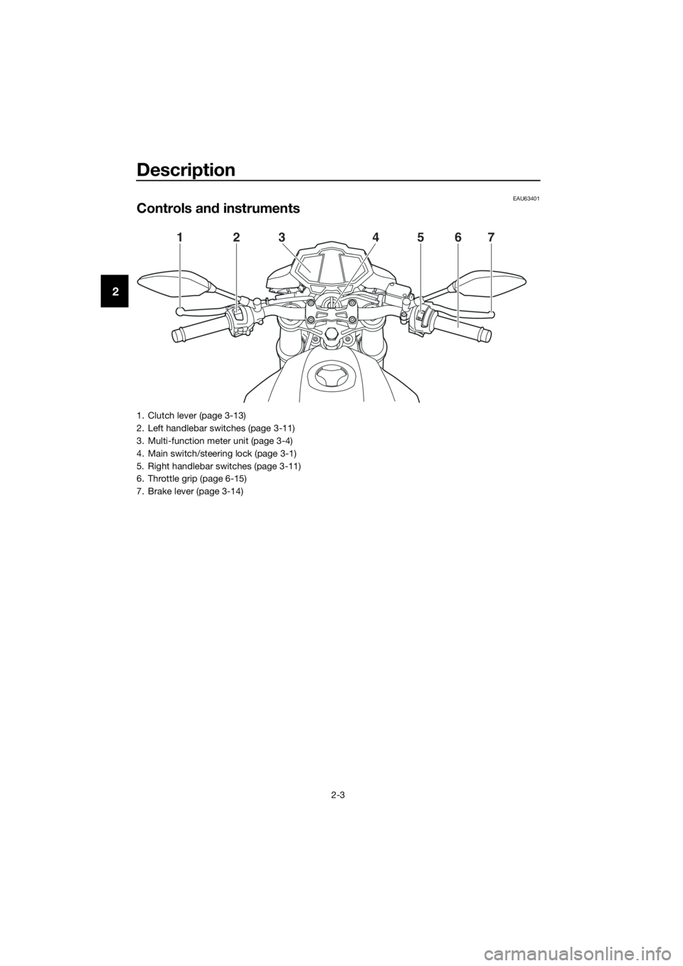
Controls and instruments
1234567
1. Clutch lever (page 3-13)
2. Left handlebar switches (page 3-11)
3. Multi-function meter unit (page 3-4)
4. Main switch/steering lock (page 3-1)
5. Right handlebar switches (page 3-11)
6. Throttle grip (page 6-15)
7. Brake lever (page 3-14)
UBR3E0E0.book Page 3 Friday, June 19, 2015 1:19 PM
Page 15 of 98
Instrument and control functions
3-1
3
EAU10462
Main switch/steering lock
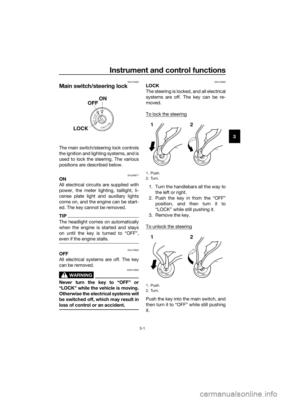
The main switch/steering lock controls
the ignition and lighting systems, and is
used to lock the steering. The various
positions are described below.
EAU36871ON
All electrical circuits are supplied with
power, the meter lighting, taillight, li-
cense plate light and auxiliary lights
come on, and the engine can be start-
ed. The key cannot be removed.
TIP
The headlight comes on automatically
when the engine is started and stays
even if the engine stalls.
EAU10662OFF
All electrical systems are off. The key
can be removed.
WARNING
EWA10062
Never turn the key to “OFF” or
“LOCK” while the vehicle is moving.
Otherwise the electrical systems will
be switched off, which may result in
loss of control or an accident.
EAU10693LOCK
The steering is locked, and all electrical
systems are off. The key can be re-
moved.
To lock the steering
1. Turn the handlebars all the way to
the left or right.
2. Push the key in from the “OFF”
position, and then turn it to
“LOCK” while still pushing it.
3. Remove the key.
To unlock the steering
Push the key into the main switch, and
then turn it to “OFF” while still pushing
it.
1. Push.
2. Turn.
1. Push.
2. Turn.
12
12
UBR3E0E0.book Page 1 Friday, June 19, 2015 1:19 PM
Page 16 of 98
Instrument and control functions
3-2
3
EAU49398
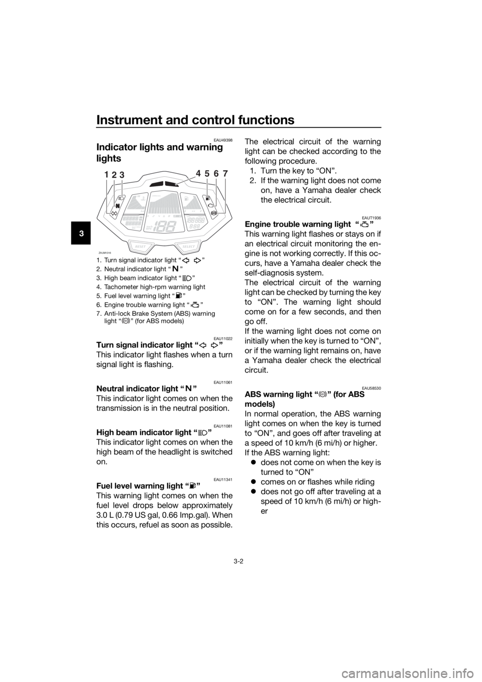
Indicator lights and warning
lights
EAU11022Turn signal indicator light “ ”
This indicator light flashes when a turn
signal light is flashing.
EAU11061Neutral indicator light “ ”
This indicator light comes on when the
transmission is in the neutral position.
EAU11081High beam indicator light “ ”
This indicator light comes on when the
high beam of the headlight is switched
on.
EAU11341Fuel level warning light “ ”
This warning light comes on when the
fuel level drops below approximately
3.0 L (0.79 US gal, 0.66 Imp.gal). When
this occurs, refuel as soon as possible.The electrical circuit of the warning
light can be checked according to the
following procedure.
1. Turn the key to “ON”.
2. If the warning light does not come
on, have a Yamaha dealer check
the electrical circuit.
EAUT1936Engine trouble warning light “ ”
This warning light flashes or stays on if
an electrical circuit monitoring the en-
gine is not working correctly. If this oc-
curs, have a Yamaha dealer check the
self-diagnosis system.
The electrical circuit of the warning
light can be checked by turning the key
to “ON”. The warning light should
come on for a few seconds, and then
go off.
If the warning light does not come on
initially when the key is turned to “ON”,
or if the warning light remains on, have
a Yamaha dealer check the electrical
circuit.
EAU58530ABS warning light “ ” (for ABS
models)
In normal operation, the ABS warning
light comes on when the key is turned
to “ON”, and goes off after traveling at
a speed of 10 km/h (6 mi/h) or higher.
If the ABS warning light:
does not come on when the key is
turned to “ON”
comes on or flashes while riding
does not go off after traveling at a
speed of 10 km/h (6 mi/h) or high-
er
1. Turn signal indicator light “ ”
2. Neutral indicator light “ ”
3. High beam indicator light “ ”
4. Tachometer high-rpm warning light
5. Fuel level warning light “ ”
6. Engine trouble warning light “ ”
7. Anti-lock Brake System (ABS) warning
light “ ” (for ABS models)
Lo
Hi
1/2
x1000r/min
ZAUM1316SELECTRESET
km/L/100kmMPGkm/h
MPH
ODOFTRIP12OILOIL
1235467
ABS
ABS
UBR3E0E0.book Page 2 Friday, June 19, 2015 1:19 PM
Page 17 of 98
Instrument and control functions
3-3
3 The ABS may not work correctly. If any
of the above occurs, have a Yamaha
dealer check the system as soon as
possible. (See page 3-15 for an expla-
nation of the ABS.)
WARNING
EWA16041
If the ABS warning light does not go
off after traveling at a speed of 10
km/h (6 mi/h) or higher, or if the
warning light comes on or flashes
while riding, the brake system re-
verts to conventional braking. If ei-
ther of the above occurs, or if the
warning light does not come on at
all, use extra caution to avoid possi-
ble wheel lock during emergency
braking. Have a Yamaha dealer
check the brake system and electri-
cal circuits as soon as possible.
EAUM3440Tachometer high-rpm warning light
This light flashes at 9500 r/min to warn
you that the engine speed is about to
enter the high-rpm zone. Once the en-
gine speed reaches 10000 r/min, this
light will come on to warn you that it is
necessary to shift up to avoid engine
damage.
To activate or deactivate the tachome-
ter high-rpm warning light, hold the
“INFO” button pushed, turn the key to
“ON”, and when the tachometer high-
rpm warning light starts flashing, press
the “SELECT” button.
TIP
When activating or deactivating the
warning light the function, after press-
come on to indicate that the function is
activated or the light will go off to indi-
cate that the function is deactivated.
UBR3E0E0.book Page 3 Friday, June 19, 2015 1:19 PM
Page 18 of 98

Instrument and control functions
3-4
3
EAUM3422
Multi-function meter unit
WARNING
EWA12423
Be sure to stop the vehicle before
making any setting changes to the
multi-function meter unit. Changing
settings while riding can distract the
operator and increase the risk of an
accident.
The multi-function meter unit is
equipped with the following:a speedometer
a tachometer
a clock
a fuel meter
a coolant temperature meter
an odometer and tripmeter display
a multi-function display
a self-diagnosis device
TIP
B e s u r e t o t u r n t h e k e y t o “ O N ” b e -
fore using the “SELECT”, “RE-
SET” and “INFO” buttons.
When the key is turned to “ON”, all
display segments of the multi-
function meter unit will momen-
tarily appear in order to test the
electrical circuit. The speedome-
ter, tachometer, fuel meter and
coolant temperature meter will
then perform a display check and
a welcome message will scroll
across the multi-function display.
For the U.K. only: To switch the
speedometer and multi-function
displays between kilometers and
miles, press the “SELECT” and
“RESET” button together, turn the
key to “ON” and then release the
buttons. Press the “SELECT” but-
ton to switch between kilometers
and miles and then press the “SE-
LECT” button for two seconds to
confirm the setting.
1. “INFO” switch
2. “RESET” button
3. “SELECT” button
1. Coolant temperature meter
2. Tachometer
3. Fuel meter
4. Odometer/tripmeter/fuel reserve tripmeter
5. Clock
6. Error code display
7. Speedometer
8. Multi-function display
Lo1/2ODO
ZAUM1299
SELECTRESET
INFO
km/L/100kmMPGkm/h
MPH
ODOFTRIPx1000r/minOILOIL
23
1
Lo
Hi
1/2
x1000r/min
ZAUM1300
km/h
ODOOIL
123
45678
UBR3E0E0.book Page 4 Friday, June 19, 2015 1:19 PM
Page 19 of 98

Instrument and control functions
3-5
3 Tachometer
The tachometer allows the rider to
monitor the engine speed and keep it
within the ideal power range.
When the key is turned to “ON”, the ta-
chometer will sweep across the r/min
range and then return to zero r/min in
order to test the electrical circuit.
NOTICE
ECAM1150
Do not operate the engine in the ta-
chometer high-rpm zone.
High-rpm zone: 10000 r/min and
above
Clock
The clock displays when the key is
turned to “ON”. To set the clock
1. Turn the key to “ON”.
2. Push the “SELECT” button for at
least two seconds.
3. When the hour digits start flash-
ing, use the “RESET” button to set
the hours.
4. Push the “SELECT” button , and
the minute digits will start flashing.
5. Use the “RESET” button to set the
minutes.
6. Push the “SELECT” button and
then release it to start the clock.
TIP
When setting the hours and minutes,
crease the increment value one by one,
or push and hold the button to increase
the increment value continuously.
Fuel meter
The fuel meter indicates the amount of
fuel in the fuel tank. The display seg-
ments of the fuel meter disappear to-
wards “E” (Empty) as the fuel level
decreases. When the fuel level be-
comes low, the last segment will flash,
(“LOW FUEL” message will also ap-
1. Tachometer
2. High-rpm zone
1. Clock
x1000r/min
ZAUM1301
km/h
1
2
1/2
ZAUM1302
ODOTRIP1
1
1. Fuel meter
2. Fuel level warning light Ž
3. Fuel reserve tripmeter
4. Information display
Lo
Hi
1/2
x1000r/min
ZAUM1303
km/h
FTRIP
21
34
UBR3E0E0.book Page 5 Friday, June 19, 2015 1:19 PM
Page 29 of 98
Instrument and control functions
3-15
3
EAU60021
ABS (for ABS models)
The Yamaha ABS (Anti-lock Brake
System) features a dual electronic con-
trol system, which acts on the front and
rear brakes independently.
Operate the brakes with ABS as you
would conventional brakes. If the ABS
is activated, a pulsating sensation may
be felt at the brake lever or brake ped-
al. In this situation, continue to apply
the brakes and let the ABS work; do
not “pump” the brakes as this will re-
duce braking effectiveness.
WARNING
EWA16051
Always keep a sufficient distance
from the vehicle ahead to match the
riding speed even with ABS.
The ABS performs best with
long braking distances.
On certain surfaces, such as
rough or gravel roads, the brak-
ing distance may be longer with
the ABS than without.
The ABS is monitored by an ECU,
which will revert the system to conven-
tional braking if a malfunction occurs.
TIP
The ABS performs a self-diagno-
sis test each time the vehicle first
starts off after the key is turned to
“ON” and the vehicle has traveled
at a speed of 10 km/h (6 mi/h) or
higher. During this test, a “click-
ing” noise can be heard from the
hydraulic control unit, and if the
brake lever or brake pedal is even
slightly applied, a vibration can be
felt at the lever and pedal, but
these do not indicate a malfunc-
tion.This ABS has a test mode which
allows the owner to experience
the pulsation at the brake lever or
brake pedal when the ABS is op-
erating. However, special tools are
required, so please consult your
Yamaha dealer.
NOTICE
ECA20100
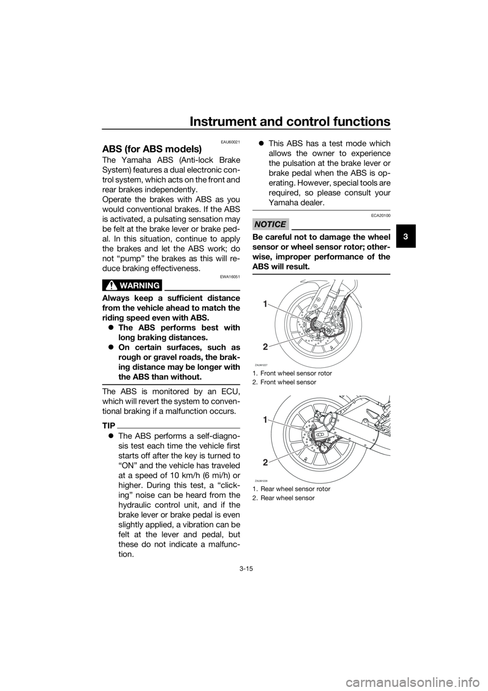
Be careful not to damage the wheel
sensor or wheel sensor rotor; other-
wise, improper performance of the
ABS will result.
1. Front wheel sensor rotor
2. Front wheel sensor
1. Rear wheel sensor rotor
2. Rear wheel sensor
ZAUM1227
1
2
ZAUM1228
1
2
UBR3E0E0.book Page 15 Friday, June 19, 2015 1:19 PM
Page 30 of 98
Instrument and control functions
3-16
3
EAUM2082
Fuel tank cap
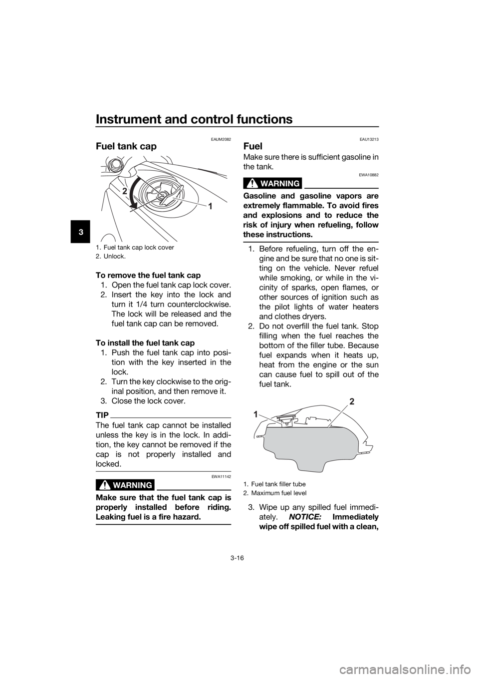
To remove the fuel tank cap
1. Open the fuel tank cap lock cover.
2. Insert the key into the lock and
turn it 1/4 turn counterclockwise.
The lock will be released and the
fuel tank cap can be removed.
To install the fuel tank cap
1. Push the fuel tank cap into posi-
tion with the key inserted in the
lock.
2. Turn the key clockwise to the orig-
inal position, and then remove it.
3. Close the lock cover.
TIP
The fuel tank cap cannot be installed
unless the key is in the lock. In addi-
tion, the key cannot be removed if the
cap is not properly installed and
locked.
WARNING
EWA11142
Make sure that the fuel tank cap is
properly installed before riding.
Leaking fuel is a fire hazard.
EAU13213
Fuel
Make sure there is sufficient gasoline in
the tank.
WARNING
EWA10882
Gasoline and gasoline vapors are
extremely flammable. To avoid fires
and explosions and to reduce the
risk of injury when refueling, follow
these instructions.
1. Before refueling, turn off the en-
gine and be sure that no one is sit-
ting on the vehicle. Never refuel
while smoking, or while in the vi-
cinity of sparks, open flames, or
other sources of ignition such as
the pilot lights of water heaters
and clothes dryers.
2. Do not overfill the fuel tank. Stop
filling when the fuel reaches the
bottom of the filler tube. Because
fuel expands when it heats up,
heat from the engine or the sun
can cause fuel to spill out of the
fuel tank.
3. Wipe up any spilled fuel immedi-
ately. NOTICE: Immediately
wipe off spilled fuel with a clean,1. Fuel tank cap lock cover
2. Unlock.
1. Fuel tank filler tube
2. Maximum fuel level
UBR3E0E0.book Page 16 Friday, June 19, 2015 1:19 PM
Page 32 of 98
Instrument and control functions
3-18
3
EAU13434
Catalytic converter
This model is equipped with a catalytic
converter in the exhaust system.
WARNING
EWA10863
The exhaust system is hot after op-
eration. To prevent a fire hazard or
burns:
Do not park the vehicle near
possible fire hazards such as
grass or other materials that
easily burn.
Park the vehicle in a place
where pedestrians or children
are not likely to touch the hot
exhaust system.
Make sure that the exhaust sys-
tem has cooled down before
doing any maintenance work.
Do not allow the engine to idle
more than a few minutes. Long
idling can cause a build-up of
heat.
NOTICE
ECA10702
Use only unleaded gasoline. The use
of leaded gasoline will cause unre-
pairable damage to the catalytic
converter.
EAUM2461
Rider seat
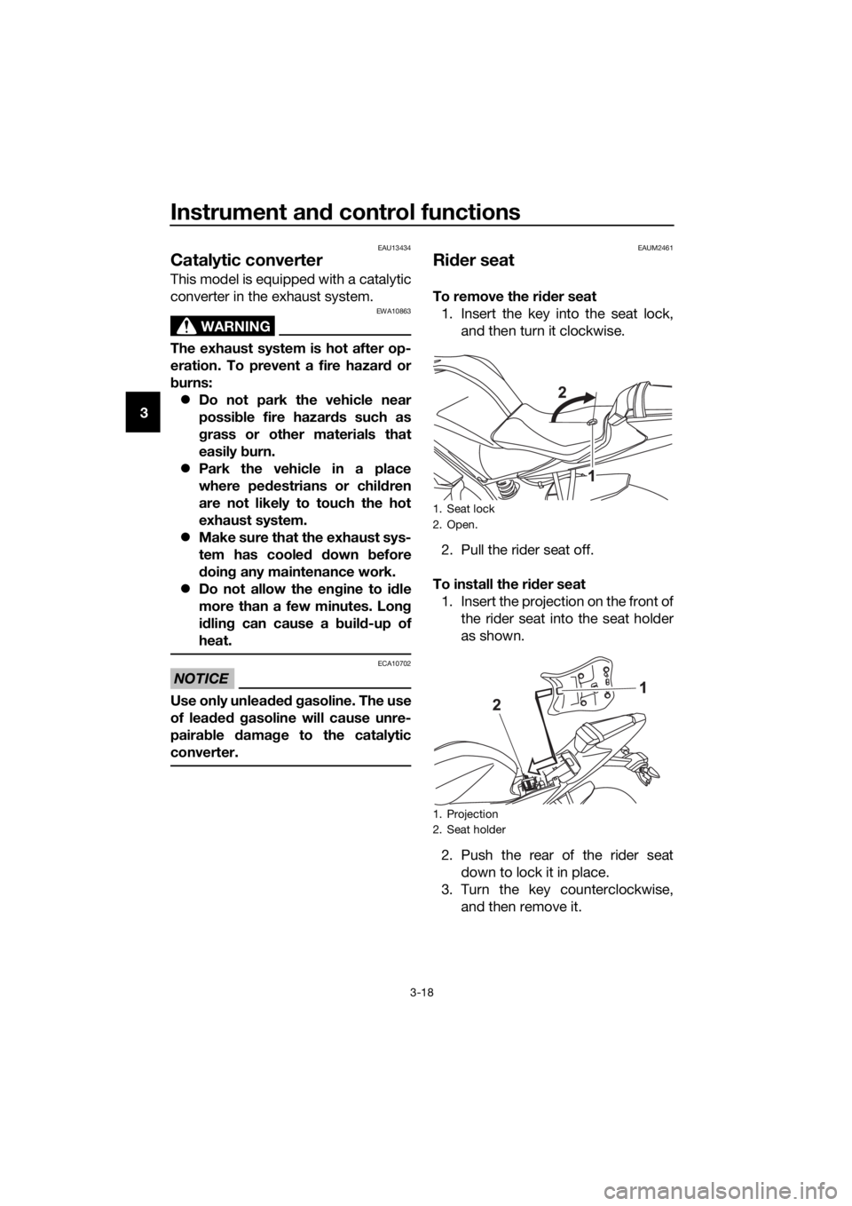
To remove the rider seat
1. Insert the key into the seat lock,
and then turn it clockwise.
2. Pull the rider seat off.
To install the rider seat
1. Insert the projection on the front of
the rider seat into the seat holder
as shown.
2. Push the rear of the rider seat
down to lock it in place.
3. Turn the key counterclockwise,
and then remove it.
1. Seat lock
2. Open.
1. Projection
2. Seat holder
UBR3E0E0.book Page 18 Friday, June 19, 2015 1:19 PM