rear brake YAMAHA MT-125 2018 Owners Manual
[x] Cancel search | Manufacturer: YAMAHA, Model Year: 2018, Model line: MT-125, Model: YAMAHA MT-125 2018Pages: 96, PDF Size: 7.1 MB
Page 5 of 96

Table of contents
Safety information............................1-1
Description........................................2-1
Left view ..........................................2-1
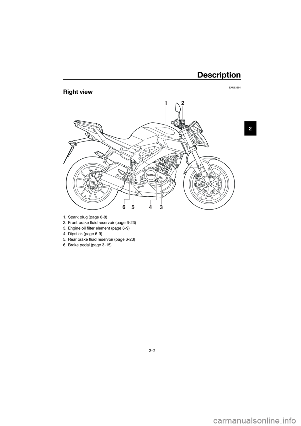
Right view........................................2-2
Controls and instruments ................2-3
Instrument and control functions....3-1
Main switch/steering lock ...............3-1
Indicator lights and warning
lights ............................................3-2
Multi-function meter unit .................3-4
Handlebar switches.......................3-12
Clutch lever ...................................3-13
Shift pedal .....................................3-14
Brake lever ....................................3-14
Brake pedal ...................................3-15
ABS ...............................................3-15
Fuel tank cap.................................3-16
Fuel................................................3-17
Catalytic converter ........................3-18
Rider seat ......................................3-19
Sidestand ......................................3-20
Ignition circuit cut-off system........3-20
For your safety – pre-operation
checks...............................................4-1
Operation and important riding
points.................................................5-1
Starting the engine ..........................5-2
Shifting ............................................5-3
Tips for reducing fuel
consumption ................................5-4
Engine break-in ...............................5-4
Parking ............................................5-5
Periodic maintenance and
adjustment........................................6-1
Owner’s tool kit ...............................6-2
Periodic maintenance chart for the
emission control system ..............6-3
General maintenance and
lubrication chart ...........................6-4
Removing and installing cowlings ...6-7
Checking the spark plug .................6-8Engine oil and oil filter element ....... 6-9
Coolant ......................................... 6-12
Replacing the air filter element
and cleaning the check hose..... 6-14
Checking the engine idling
speed......................................... 6-14
Adjusting the throttle grip free
play ............................................ 6-15
Valve clearance ............................. 6-16
Tires .............................................. 6-16
Cast wheels .................................. 6-19
Adjusting the clutch lever free
play ............................................ 6-19
Checking the front brake lever
free play ..................................... 6-20
Adjusting the brake pedal free
play ............................................ 6-21
Brake light switches ...................... 6-21
Checking the front and rear brake
pads........................................... 6-22
Checking the brake fluid level....... 6-23
Changing the brake fluid............... 6-24
Drive chain slack ........................... 6-24
Cleaning and lubricating the drive
chain .......................................... 6-26
Checking and lubricating the
cables ........................................ 6-26
Checking and lubricating the
throttle grip and cable ............... 6-27
Checking and lubricating the
brake and clutch levers ............. 6-27
Checking and lubricating the
brake pedal................................ 6-28
Checking and lubricating the
sidestand ................................... 6-28
Lubricating the swingarm
pivots ......................................... 6-29
Checking the front fork ................. 6-29
Checking the steering ................... 6-30
Checking the wheel bearings ....... 6-30
Battery .......................................... 6-31
Replacing the fuses ...................... 6-32
Replacing the headlight bulb ........ 6-33
Auxiliary lights ............................... 6-35
Tail/brake light .............................. 6-35
UBR3E1E0.book Page 1 Wednesday, August 10, 2016 9:45 AM
Page 13 of 96
Description
2-2
2
EAU63391
Right view
YAMAHA
12
3546
1. Spark plug (page 6-8)
2. Front brake fluid reservoir (page 6-23)
3. Engine oil filter element (page 6-9)
4. Dipstick (page 6-9)
5. Rear brake fluid reservoir (page 6-23)
6. Brake pedal (page 3-15)
UBR3E1E0.book Page 2 Wednesday, August 10, 2016 9:45 AM
Page 29 of 96
Instrument and control functions
3-15
3
EAU12944
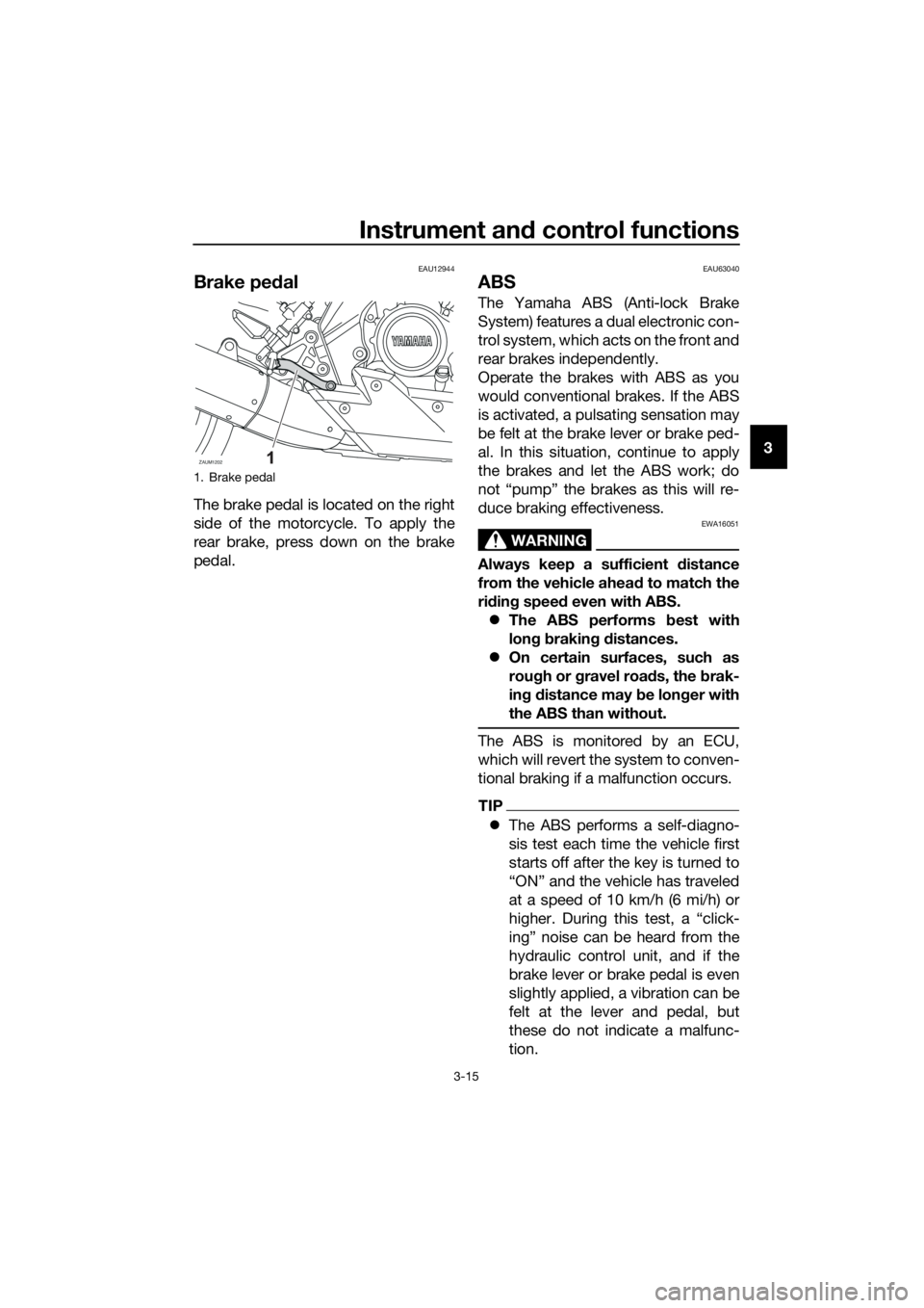
Brake pedal
The brake pedal is located on the right
side of the motorcycle. To apply the
rear brake, press down on the brake
pedal.
EAU63040
ABS
The Yamaha ABS (Anti-lock Brake
System) features a dual electronic con-
trol system, which acts on the front and
rear brakes independently.
Operate the brakes with ABS as you
would conventional brakes. If the ABS
is activated, a pulsating sensation may
be felt at the brake lever or brake ped-
al. In this situation, continue to apply
the brakes and let the ABS work; do
not “pump” the brakes as this will re-
duce braking effectiveness.
WARNING
EWA16051
Always keep a sufficient distance
from the vehicle ahead to match the
riding speed even with ABS.
The ABS performs best with
long braking distances.
On certain surfaces, such as
rough or gravel roads, the brak-
ing distance may be longer with
the ABS than without.
The ABS is monitored by an ECU,
which will revert the system to conven-
tional braking if a malfunction occurs.
TIP
The ABS performs a self-diagno-
sis test each time the vehicle first
starts off after the key is turned to
“ON” and the vehicle has traveled
at a speed of 10 km/h (6 mi/h) or
higher. During this test, a “click-
ing” noise can be heard from the
hydraulic control unit, and if the
brake lever or brake pedal is even
slightly applied, a vibration can be
felt at the lever and pedal, but
these do not indicate a malfunc-
tion.
1. Brake pedal
ZAUM1202
UBR3E1E0.book Page 15 Wednesday, August 10, 2016 9:45 AM
Page 30 of 96
Instrument and control functions
3-16
3This ABS has a test mode which
allows the owner to experience
the pulsation at the brake lever or
brake pedal when the ABS is op-
erating. However, special tools are
required, so please consult your
Yamaha dealer.
NOTICE
ECA20100
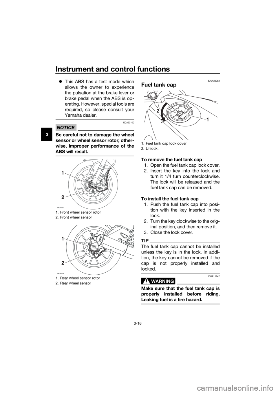
Be careful not to damage the wheel
sensor or wheel sensor rotor; other-
wise, improper performance of the
ABS will result.
EAUM2082
Fuel tank cap
To remove the fuel tank cap
1. Open the fuel tank cap lock cover.
2. Insert the key into the lock and
turn it 1/4 turn counterclockwise.
The lock will be released and the
fuel tank cap can be removed.
To install the fuel tank cap
1. Push the fuel tank cap into posi-
tion with the key inserted in the
lock.
2. Turn the key clockwise to the orig-
inal position, and then remove it.
3. Close the lock cover.
TIP
The fuel tank cap cannot be installed
unless the key is in the lock. In addi-
tion, the key cannot be removed if the
cap is not properly installed and
locked.
WARNING
EWA11142
Make sure that the fuel tank cap is
properly installed before riding.
Leaking fuel is a fire hazard.
1. Front wheel sensor rotor
2. Front wheel sensor
1. Rear wheel sensor rotor
2. Rear wheel sensor
ZAUM1227
1
2
ZAUM1228
1
2
1. Fuel tank cap lock cover
2. Unlock.
UBR3E1E0.book Page 16 Wednesday, August 10, 2016 9:45 AM
Page 36 of 96
For your safety – pre-operation checks
4-1
4
EAU63440
Inspect your vehicle each time you use it to make sure the vehicle is in safe oper-
ating condition. Always follow the inspection and maintenance procedures and
schedules described in the Owner’s Manual.
WARNING
EWA11152
Failure to inspect or maintain the vehicle properly increases the possibility
of an accident or equipment damage. Do not operate the vehicle if you find
any problem. If a problem cannot be corrected by the procedures provided
in this manual, have the vehicle inspected by a Yamaha dealer.
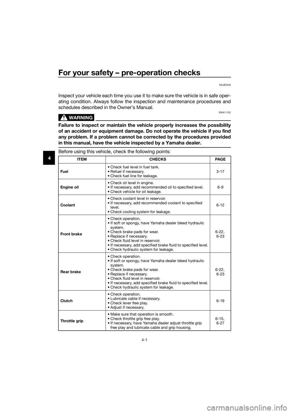
Before using this vehicle, check the following points:
ITEM CHECKS PAGE
Fuel• Check fuel level in fuel tank.
• Refuel if necessary.
• Check fuel line for leakage.3-17
Engine oil• Check oil level in engine.
• If necessary, add recommended oil to specified level.
• Check vehicle for oil leakage.6-9
Coolant• Check coolant level in reservoir.
• If necessary, add recommended coolant to specified
level.
• Check cooling system for leakage.6-12
Front brake• Check operation.
• If soft or spongy, have Yamaha dealer bleed hydraulic
system.
• Check brake pads for wear.
• Replace if necessary.
• Check fluid level in reservoir.
• If necessary, add specified brake fluid to specified level.
• Check hydraulic system for leakage.6-22,
6-23
Rear brake• Check operation.
• If soft or spongy, have Yamaha dealer bleed hydraulic
system.
• Check brake pads for wear.
• Replace if necessary.
• Check fluid level in reservoir.
• If necessary, add specified brake fluid to specified level.
• Check hydraulic system for leakage.6-22,
6-23
Clutch• Check operation.
• Lubricate cable if necessary.
• Check lever free play.
• Adjust if necessary.6-19
Throttle grip• Make sure that operation is smooth.
• Check throttle grip free play.
• If necessary, have Yamaha dealer adjust throttle grip
free play and lubricate cable and grip housing.6-15,
6-27
UBR3E1E0.book Page 1 Wednesday, August 10, 2016 9:45 AM
Page 46 of 96
Periodic maintenance and adjustment
6-4
6
EAU71361
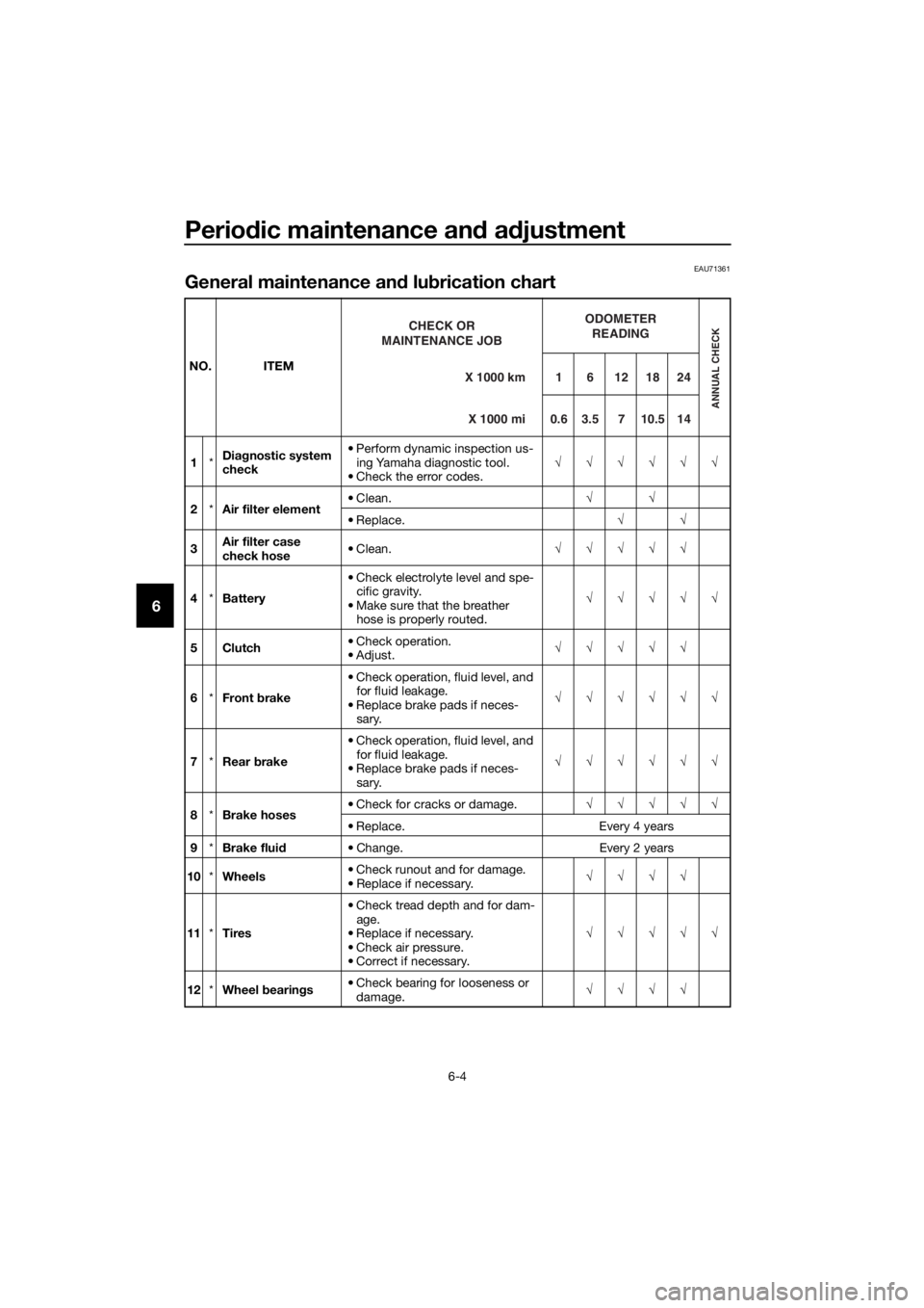
General maintenance and lubrication chart
NO. ITEM
1*Diagnostic system
check• Perform dynamic inspection us-
ing Yamaha diagnostic tool.
• Check the error codes.√√√√√√
2*Air filter element• Clean.√√
• Replace.√√
3Air filter case
check hose• Clean.√√√√√
4*Battery• Check electrolyte level and spe-
cific gravity.
• Make sure that the breather
hose is properly routed.√√√√√
5Clutch• Check operation.
•Adjust.√√√√√
6*Front brake• Check operation, fluid level, and
for fluid leakage.
• Replace brake pads if neces-
sary.√√√√√√
7*Rear brake• Check operation, fluid level, and
for fluid leakage.
• Replace brake pads if neces-
sary.√√√√√√
8*Brake hoses• Check for cracks or damage.√√√√√
• Replace. Every 4 years
9*Brake fluid• Change. Every 2 years
10*Wheels• Check runout and for damage.
• Replace if necessary.√√√√
11*Tires• Check tread depth and for dam-
age.
• Replace if necessary.
• Check air pressure.
• Correct if necessary.√√√√√
12*Wheel bearings• Check bearing for looseness or
damage.√√√√X 1000 km CHECK OR
MAINTENANCE JOB
X 1000 miODOMETER
READINGANNUAL CHECK
1 6 12 18 24
0.6 3.5 7 10.5 14
UBR3E1E0.book Page 4 Wednesday, August 10, 2016 9:45 AM
Page 47 of 96
Periodic maintenance and adjustment
6-5
6
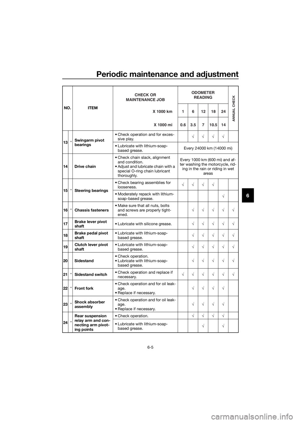
13*Swingarm pivot
bearings• Check operation and for exces-
sive play.√√√√
• Lubricate with lithium-soap-
based grease.Every 24000 km (14000 mi)
14 Drive chain• Check chain slack, alignment
and condition.
• Adjust and lubricate chain with a
special O-ring chain lubricant
thoroughly.Every 1000 km (600 mi) and af-
ter washing the motorcycle, rid-
ing in the rain or riding in wet
areas
15*Steering bearings• Check bearing assemblies for
looseness.√√√√
• Moderately repack with lithium-
soap-based grease.√
16*Chassis fasteners• Make sure that all nuts, bolts
and screws are properly tight-
ened.√√√√√
17Brake lever pivot
shaft• Lubricate with silicone grease.√√√√√
18Brake pedal pivot
shaft• Lubricate with lithium-soap-
based grease.√√√√√
19Clutch lever pivot
shaft• Lubricate with lithium-soap-
based grease.√√√√√
20 Sidestand• Check operation.
• Lubricate with lithium-soap-
based grease.√√√√√
21*Sidestand switch• Check operation and replace if
necessary.√√√√√√
22*Front fork• Check operation and for oil leak-
age.
• Replace if necessary.√√√√
23*Shock absorber
assembly• Check operation and for oil leak-
age.
• Replace if necessary.√√√√
24*Rear suspension
relay arm and con-
necting arm pivot-
ing points• Check operation.√√√√
• Lubricate with lithium-soap-
based grease.√√ NO. ITEM
X 1000 km CHECK OR
MAINTENANCE JOB
X 1000 mi
ODOMETER
READING
ANNUAL CHECK
16121824
0.63.5710.514
UBR3E1E0.book Page 5 Wednesday, August 10, 2016 9:45 AM
Page 48 of 96

Periodic maintenance and adjustment
6-6
6
EAU72740
TIP
The air filter needs more frequent service if you are riding in unusually wet or
dusty areas.
Hydraulic brake service
• Regularly check and, if necessary, correct the brake fluid level.
• Every two years change the brake fluid.
• Replace the brake hoses every four years and if cracked or damaged.
25 Engine oil• Change (warm engine before
draining).At the initial interval and when
the oil change indicator flashes
or comes on
• Check oil level and vehicle for oil
leakage.Every 3000 km (1800 mi)
26Engine oil filter el-
ement• Replace.√√√
27*Cooling system• Check coolant level and vehicle
for coolant leakage.√√√√√
• Change. Every 3 years
28*Front and rear
brake switches• Check operation.√√√√√√
29*Moving parts and
cables• Lubricate.√√√√√
30*Throttle grip hous-
ing and cable• Check operation and free play.
• Adjust the throttle cable free
play if necessary.
• Lubricate the throttle grip hous-
ing and cable.√√√√√
31*Lights, signals and
switches• Check operation.
• Adjust headlight beam.√√√√√√ NO. ITEM
X 1000 km CHECK OR
MAINTENANCE JOB
X 1000 miODOMETER
READING
ANNUAL CHECK
16121824
0.6 3.5 7 10.5 14
UBR3E1E0.book Page 6 Wednesday, August 10, 2016 9:45 AM
Page 59 of 96
Periodic maintenance and adjustment
6-17
6
WARNING
EWA10512
Never overload your vehicle. Opera-
tion of an overloaded vehicle could
cause an accident.
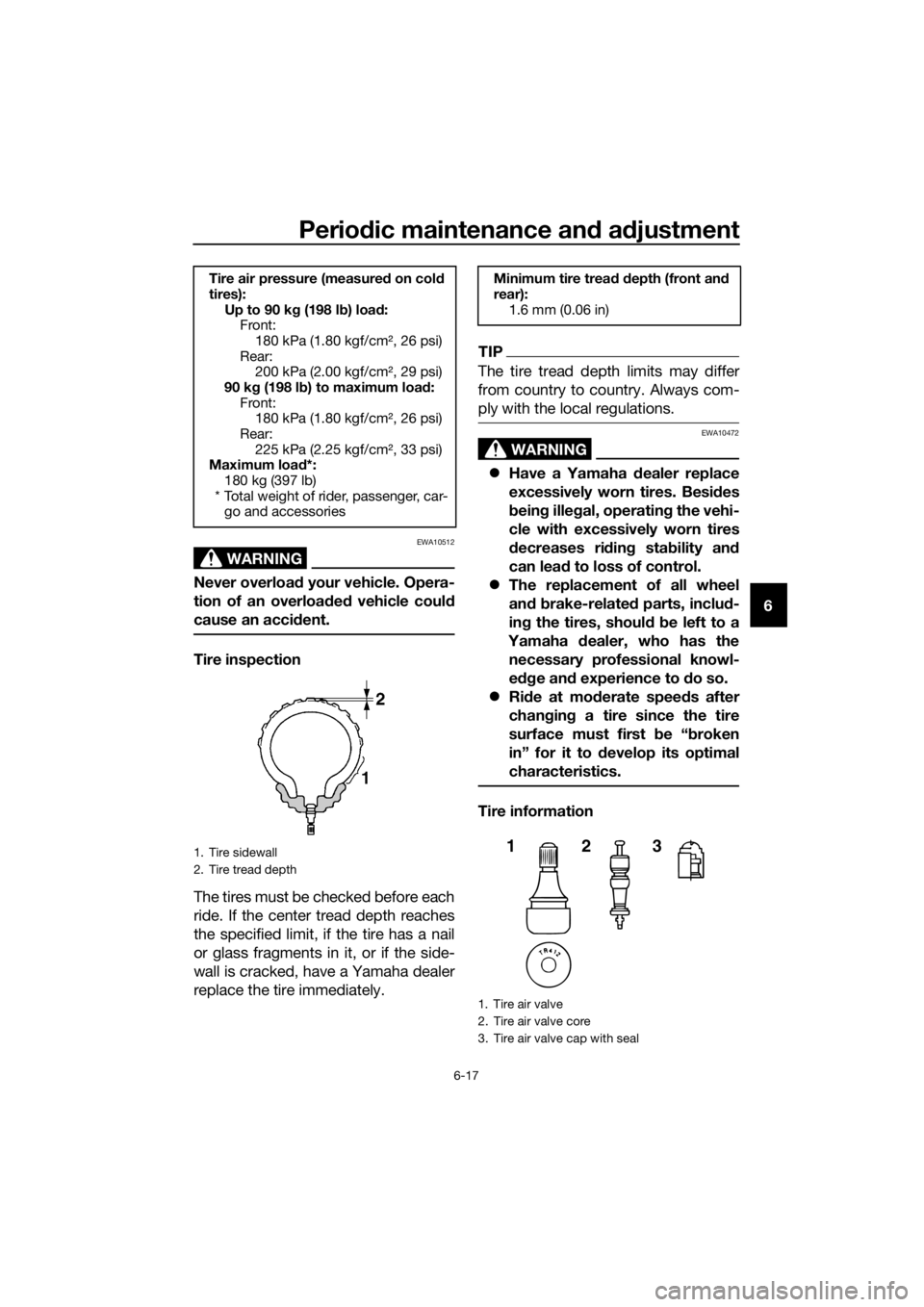
Tire inspection
The tires must be checked before each
ride. If the center tread depth reaches
the specified limit, if the tire has a nail
or glass fragments in it, or if the side-
wall is cracked, have a Yamaha dealer
replace the tire immediately.
TIP
The tire tread depth limits may differ
from country to country. Always com-
ply with the local regulations.
WARNING
EWA10472
Have a Yamaha dealer replace
excessively worn tires. Besides
being illegal, operating the vehi-
cle with excessively worn tires
decreases riding stability and
can lead to loss of control.
The replacement of all wheel
and brake-related parts, includ-
ing the tires, should be left to a
Yamaha dealer, who has the
necessary professional knowl-
edge and experience to do so.
Ride at moderate speeds after
changing a tire since the tire
surface must first be “broken
in” for it to develop its optimal
characteristics.
Tire information
Tire air pressure (measured on cold
tires):
Up to 90 kg (198 lb) load:
Front:
180 kPa (1.80 kgf/cm², 26 psi)
Rear:
200 kPa (2.00 kgf/cm², 29 psi)
90 kg (198 lb) to maximum load:
Front:
180 kPa (1.80 kgf/cm², 26 psi)
Rear:
225 kPa (2.25 kgf/cm², 33 psi)
Maximum load*:
180 kg (397 lb)
* Total weight of rider, passenger, car-
go and accessories
1. Tire sidewall
2. Tire tread depth
Minimum tire tread depth (front and
rear):
1.6 mm (0.06 in)
1. Tire air valve
2. Tire air valve core
3. Tire air valve cap with seal
123
UBR3E1E0.book Page 17 Wednesday, August 10, 2016 9:45 AM
Page 64 of 96
Periodic maintenance and adjustment
6-22
6
EAU22393
Checking the front and rear
brake pads
The front and rear brake pads must be
checked for wear at the intervals spec-
ified in the periodic maintenance and
lubrication chart.
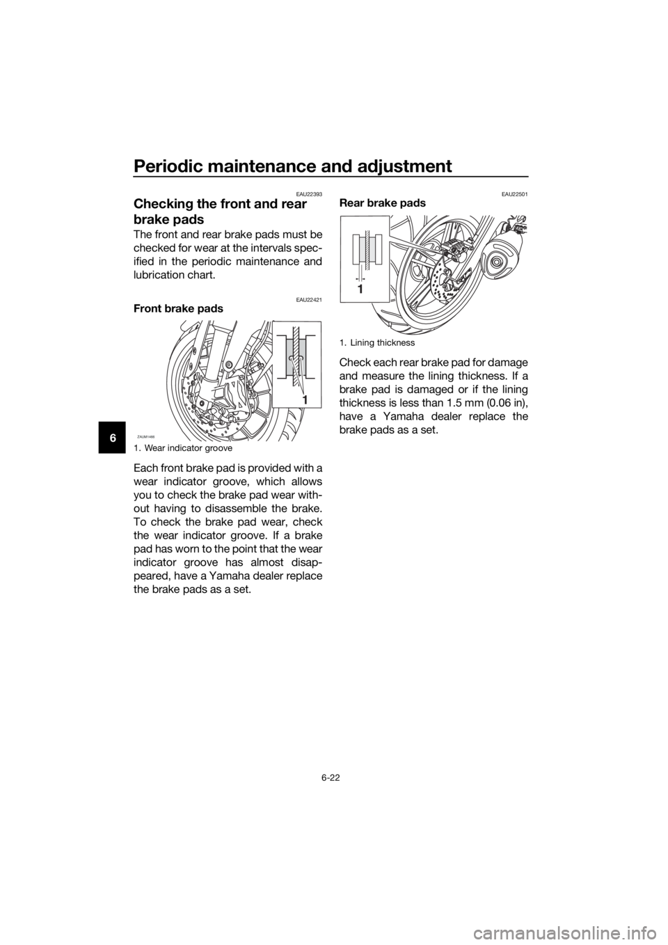
EAU22421Front brake pads
Each front brake pad is provided with a
wear indicator groove, which allows
you to check the brake pad wear with-
out having to disassemble the brake.
To check the brake pad wear, check
the wear indicator groove. If a brake
pad has worn to the point that the wear
indicator groove has almost disap-
peared, have a Yamaha dealer replace
the brake pads as a set.
EAU22501Rear brake pads
Check each rear brake pad for damage
and measure the lining thickness. If a
brake pad is damaged or if the lining
thickness is less than 1.5 mm (0.06 in),
have a Yamaha dealer replace the
brake pads as a set.
1. Wear indicator groove
ZAUM1466
1
1. Lining thickness
UBR3E1E0.book Page 22 Wednesday, August 10, 2016 9:45 AM