key YAMAHA MT-125 2020 Owners Manual
[x] Cancel search | Manufacturer: YAMAHA, Model Year: 2020, Model line: MT-125, Model: YAMAHA MT-125 2020Pages: 96, PDF Size: 8.36 MB
Page 4 of 96
Important manual information
EAU63350
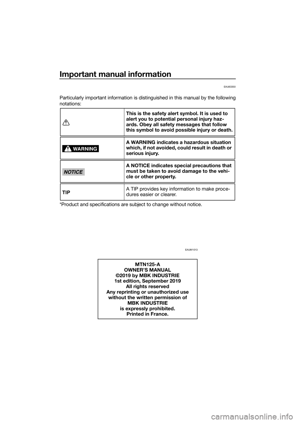
Particularly important information is distinguished in this manual by the following
notations:
*Product and specifications are subject to change without notice.
EAUM1013
This is the safety alert symbol. It is used to
alert you to potential personal injury haz-
ards. Obey all safety messages that follow
this symbol to avoid possible injury or death.
A WARNING indicates a hazardous situation
which, if not avoided, could result in death or
serious injury.
A NOTICE indicates special precautions that
must be taken to avoid damage to the vehi-
cle or other property.
A TIP provides key information to make proce-
dures easier or clearer.
MTN125-A
OWNER’S MANUAL
©2019 by MBK INDUSTRIE
1st edition, September 2019
All rights reserved
Any reprinting or unauthorized use
without the written permission of
MBK INDUSTRIE
is expressly prohibited.
Printed in France.
WARNING
NOTICE
TIP
UB6GE0E0.book Page 1 Wednesday, August 28, 2019 11:11 AM
Page 15 of 96
Instrument and control functions
3-1
3
EAU10462
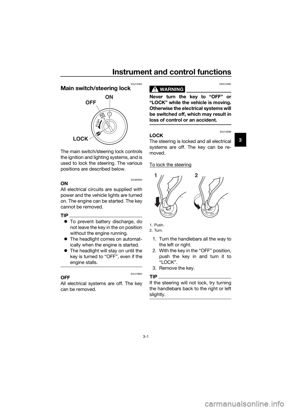
Main switch/steering lock
The main switch/steering lock controls
the ignition and lighting systems, and is
used to lock the steering. The various
positions are described below.
EAU85050ON
All electrical circuits are supplied with
power and the vehicle lights are turned
on. The engine can be started. The key
cannot be removed.
TIP
To prevent battery discharge, do
not leave the key in the on position
without the engine running.
The headlight comes on automat-
ically when the engine is started.
The headlight will stay on until the
key is turned to “OFF”, even if the
engine stalls.
EAU10662OFF
All electrical systems are off. The key
can be removed.
WARNING
EWA10062
Never turn the key to “OFF” or
“LOCK” while the vehicle is moving.
Otherwise the electrical systems will
be switched off, which may result in
loss of control or an accident.
EAU10696LOCK
The steering is locked and all electrical
systems are off. The key can be re-
moved.
To lock the steering
1. Turn the handlebars all the way to
the left or right.
2. With the key in the “OFF” position,
push the key in and turn it to
“LOCK”.
3. Remove the key.
TIP
If the steering will not lock, try turning
the handlebars back to the right or left
slightly.
1. Push.
2. Turn.
12
UB6GE0E0.book Page 1 Wednesday, August 28, 2019 11:11 AM
Page 16 of 96
Instrument and control functions
3-2
3To unlock the steering
From the “LOCK” position, push the
key and turn it to “OFF”.
EAU4939H
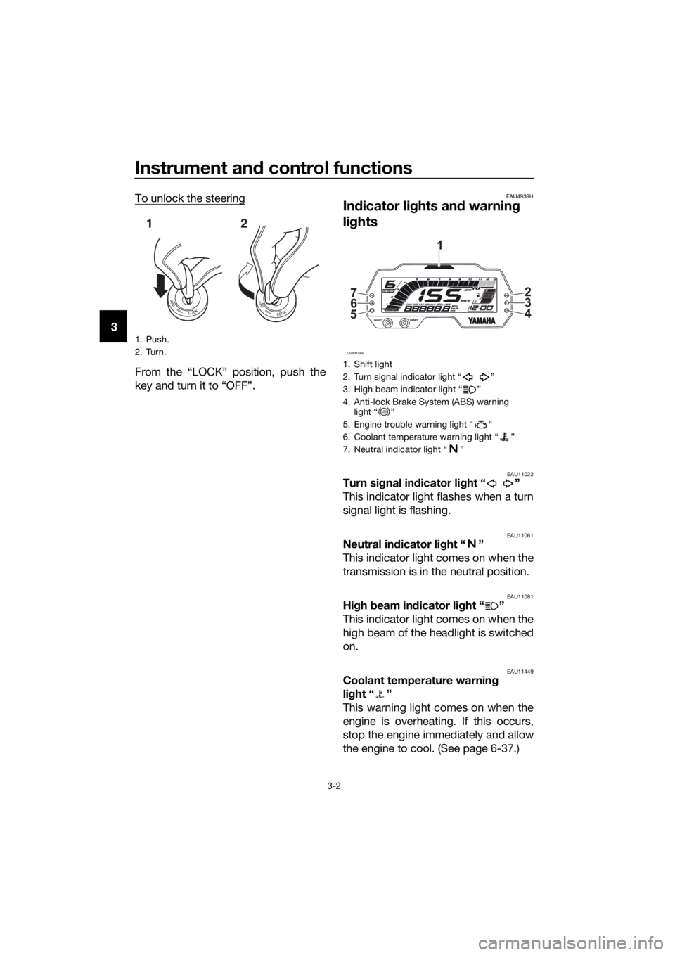
Indicator lights and warning
lights
EAU11022Turn signal indicator light “ ”
This indicator light flashes when a turn
signal light is flashing.
EAU11061Neutral indicator light “ ”
This indicator light comes on when the
transmission is in the neutral position.
EAU11081High beam indicator light “ ”
This indicator light comes on when the
high beam of the headlight is switched
on.
EAU11449Coolant temperature warning
light “ ”
This warning light comes on when the
engine is overheating. If this occurs,
stop the engine immediately and allow
the engine to cool. (See page 6-37.)
1. Push.
2. Turn.
12
1. Shift light
2. Turn signal indicator light Ž
3. High beam indicator light Ž
4. Anti-lock Brake System (ABS) warning
light Ž
5. Engine trouble warning light Ž
6. Coolant temperature warning light Ž
7. Neutral indicator light Ž
ZAUM1566
56 72
3
4
1
ABS
UB6GE0E0.book Page 2 Wednesday, August 28, 2019 11:11 AM
Page 18 of 96
Instrument and control functions
3-4
3
EAUM4010
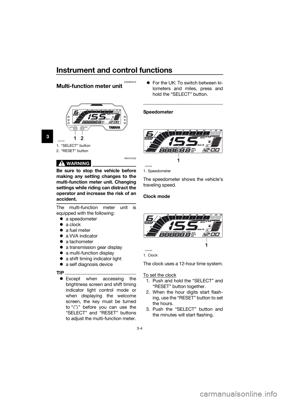
Multi-function meter unit
WARNING
EWA12423
Be sure to stop the vehicle before
making any setting changes to the
multi-function meter unit. Changing
settings while riding can distract the
operator and increase the risk of an
accident.
The multi-function meter unit is
equipped with the following:
a speedometer
a clock
a fuel meter
a VVA indicator
a tachometer
a transmission gear display
a multi-function display
a shift timing indicator light
a self diagnosis device
TIP
Except when accessing the
brightness screen and shift timing
indicator light control mode or
when displaying the welcome
screen, the key must be turned
to “ ” before you can use the
“SELECT” and “RESET” buttons
to adjust the multi-function meter.For the UK: To switch between ki-
lometers and miles, press and
hold the “SELECT” button.
Speedometer
The speedometer shows the vehicle’s
traveling speed.
Clock mode
The clock uses a 12-hour time system.
To set the clock
1. Push and hold the “SELECT” and
“RESET” button together.
2. When the hour digits start flash-
ing, use the “RESET” button to set
the hours.
3. Push the “SELECT” button and
the minutes will start flashing.
1. “SELECT” button
2. “RESET” button
ZAUM156712
1. Speedometer
1. Clock
ZAUM15681
ZAUM15691
UB6GE0E0.book Page 4 Wednesday, August 28, 2019 11:11 AM
Page 19 of 96
Instrument and control functions
3-5
3 4. Use the “RESET” button to set the
minutes.
5. Push the “SELECT” button to start
the clock.
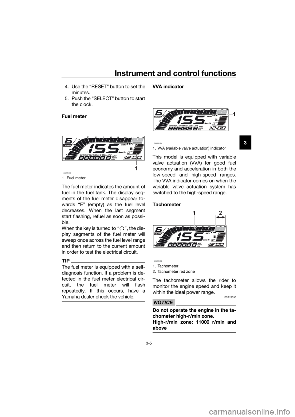
Fuel meter
The fuel meter indicates the amount of
fuel in the fuel tank. The display seg-
ments of the fuel meter disappear to-
wards “E” (empty) as the fuel level
decreases. When the last segment
start flashing, refuel as soon as possi-
ble.
When the key is turned to “ ”, the dis-
play segments of the fuel meter will
sweep once across the fuel level range
and then return to the current amount
in order to test the electrical circuit.
TIP
The fuel meter is equipped with a self-
diagnosis function. If a problem is de-
tected in the fuel meter electrical cir-
cuit, the fuel meter will flash
repeatedly. If this occurs, have a
Yamaha dealer check the vehicle.
VVA indicator
This model is equipped with variable
valve actuation (VVA) for good fuel
economy and acceleration in both the
low-speed and high-speed ranges.
The VVA indicator comes on when the
variable valve actuation system has
switched to the high-speed range.
Tachometer
The tachometer allows the rider to
monitor the engine speed and keep it
within the ideal power range.
NOTICE
ECA23050
Do not operate the engine in the ta-
chometer high-r/min zone.
High-r/min zone: 11000 r/min and
above
1. Fuel meter
ZAUM15701
1. VVA (variable valve actuation) indicator
1. Tachometer
2. Tachometer red zone
ZAUM1571
1
ZAUM1572
1
2
UB6GE0E0.book Page 5 Wednesday, August 28, 2019 11:11 AM
Page 23 of 96
Instrument and control functions
3-9
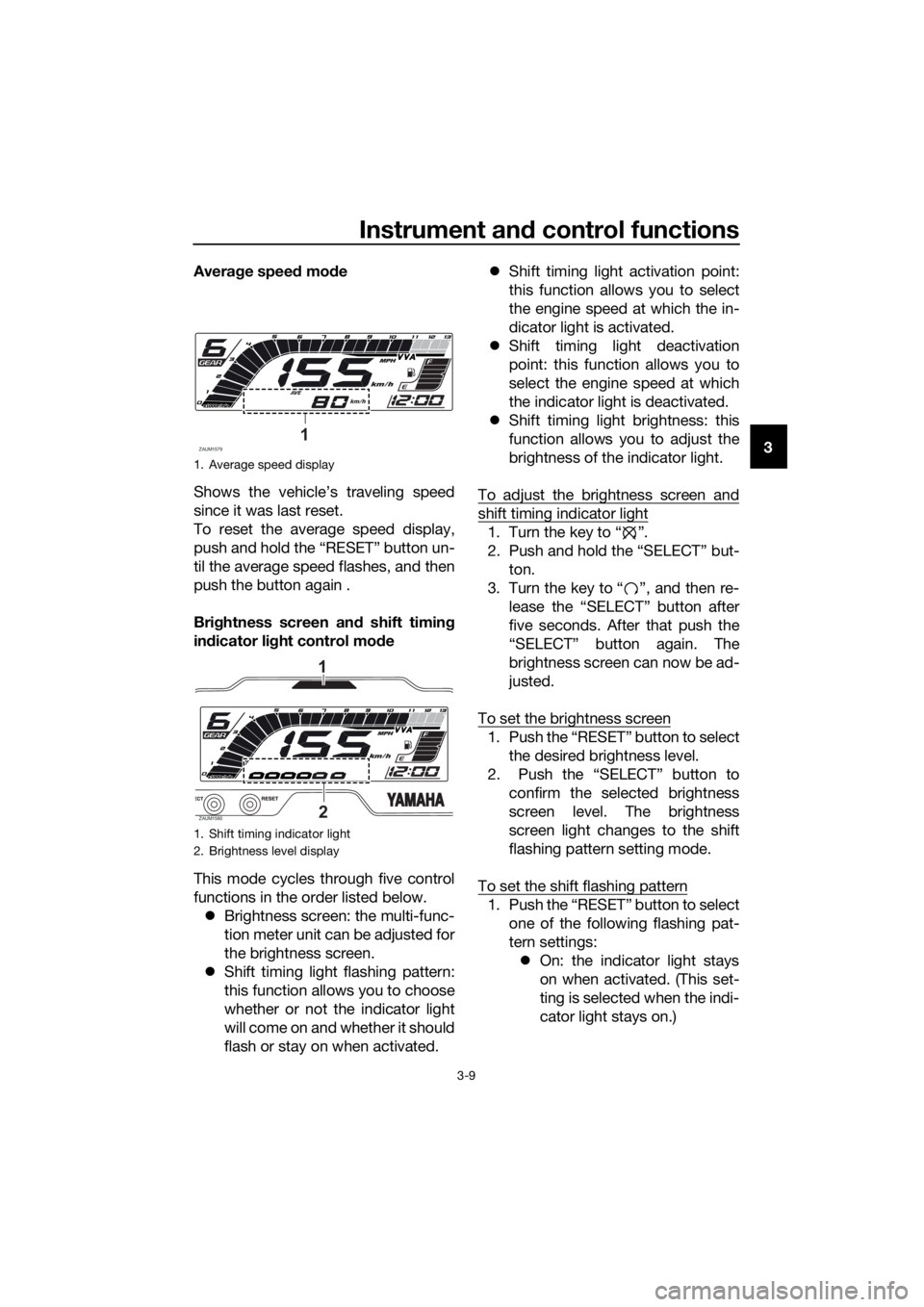
3 Average speed mode
Shows the vehicle’s traveling speed
since it was last reset.
To reset the average speed display,
push and hold the “RESET” button un-
til the average speed flashes, and then
push the button again .
Brightness screen and shift timing
indicator light control mode
This mode cycles through five control
functions in the order listed below.
Brightness screen: the multi-func-
tion meter unit can be adjusted for
the brightness screen.
Shift timing light flashing pattern:
this function allows you to choose
whether or not the indicator light
will come on and whether it should
flash or stay on when activated.Shift timing light activation point:
this function allows you to select
the engine speed at which the in-
dicator light is activated.
Shift timing light deactivation
point: this function allows you to
select the engine speed at which
the indicator light is deactivated.
Shift timing light brightness: this
function allows you to adjust the
brightness of the indicator light.
To adjust the brightness screen and
shift timing indicator light
1. Turn the key to “ ”.
2. Push and hold the “SELECT” but-
ton.
3. Turn the key to “ ”, and then re-
lease the “SELECT” button after
five seconds. After that push the
“SELECT” button again. The
brightness screen can now be ad-
justed.
To set the brightness screen
1. Push the “RESET” button to select
the desired brightness level.
2. Push the “SELECT” button to
confirm the selected brightness
screen level. The brightness
screen light changes to the shift
flashing pattern setting mode.
To set the shift flashing pattern
1. Push the “RESET” button to select
one of the following flashing pat-
tern settings:
On: the indicator light stays
on when activated. (This set-
ting is selected when the indi-
cator light stays on.)
1. Average speed display
1. Shift timing indicator light
2. Brightness level display
ZAUM15791
ZAUM15802
1
UB6GE0E0.book Page 9 Wednesday, August 28, 2019 11:11 AM
Page 24 of 96

Instrument and control functions
3-10
3Flash: the indicator light
flashes when activated. (This
setting is selected when the
indicator light flashes four
times per second.)
Off: the indicator light is deac-
tivated; in other words, it
does not come on or flash.
(This setting is selected when
the indicator light flashes
once every two seconds.)
2. Push the “SELECT” button to con-
firm the selected flashing pattern.
The shift timing indicator light
changes to the activation point
setting mode.
The tachometer will show the current
setting r/min for the activation point
and deactivation point setting modes.
To set the shift activation point
TIP
The shift timing indicator light activa-
tion point can be set between 9000
r/min and 13000 r/min. The indicator
light can be set in increments of 500
r/min.
1.
the desired engine speed for acti-
vating the indicator light.
2.
firm the selected engine speed.
The control mode changes to the
deactivation point setting mode.To set the shift deactivation point
TIP
The shift timing indicator light de-
activation point can be set be-
tween 9000 r/min and 13000
r/min. The indicator light can be
set in increments of 500 r/min.
Be sure to set the deactivation
point to a higher engine speed
than for the activation point, other-
wise the shift timing indicator light
will not come on.
1. Push the “RESET” button to select
the desired engine speed for de-
activating the indicator light.
2. Push the “SELECT” button to con-
firm the selected engine speed.
The control mode changes to the
brightness setting mode.
To adjust the shift brightness
1. Push the “RESET” button to select
the desired shift indicator light
brightness level.
2. Push the “SELECT” button to con-
firm the selected brightness level.
The display exits the shift timing
light control mode and returns to
the standard multi-function dis-
play mode.
Welcome screen
The welcome screen greets the rider
when the key is turned to “ ” with the
messages “Hi Buddy” and “see you”
when the key is turned to “ ”. The
user name “Buddy” is set as the facto-
ry default, but it can be set to your
name.
UB6GE0E0.book Page 10 Wednesday, August 28, 2019 11:11 AM
Page 25 of 96
Instrument and control functions
3-11
3 To set the user name
1. Turn the key to “ ”.
2. Push and hold the “RESET” but-
ton.
3. Turn the key to “ ”, and then re-
lease the “RESET” button after
four seconds.
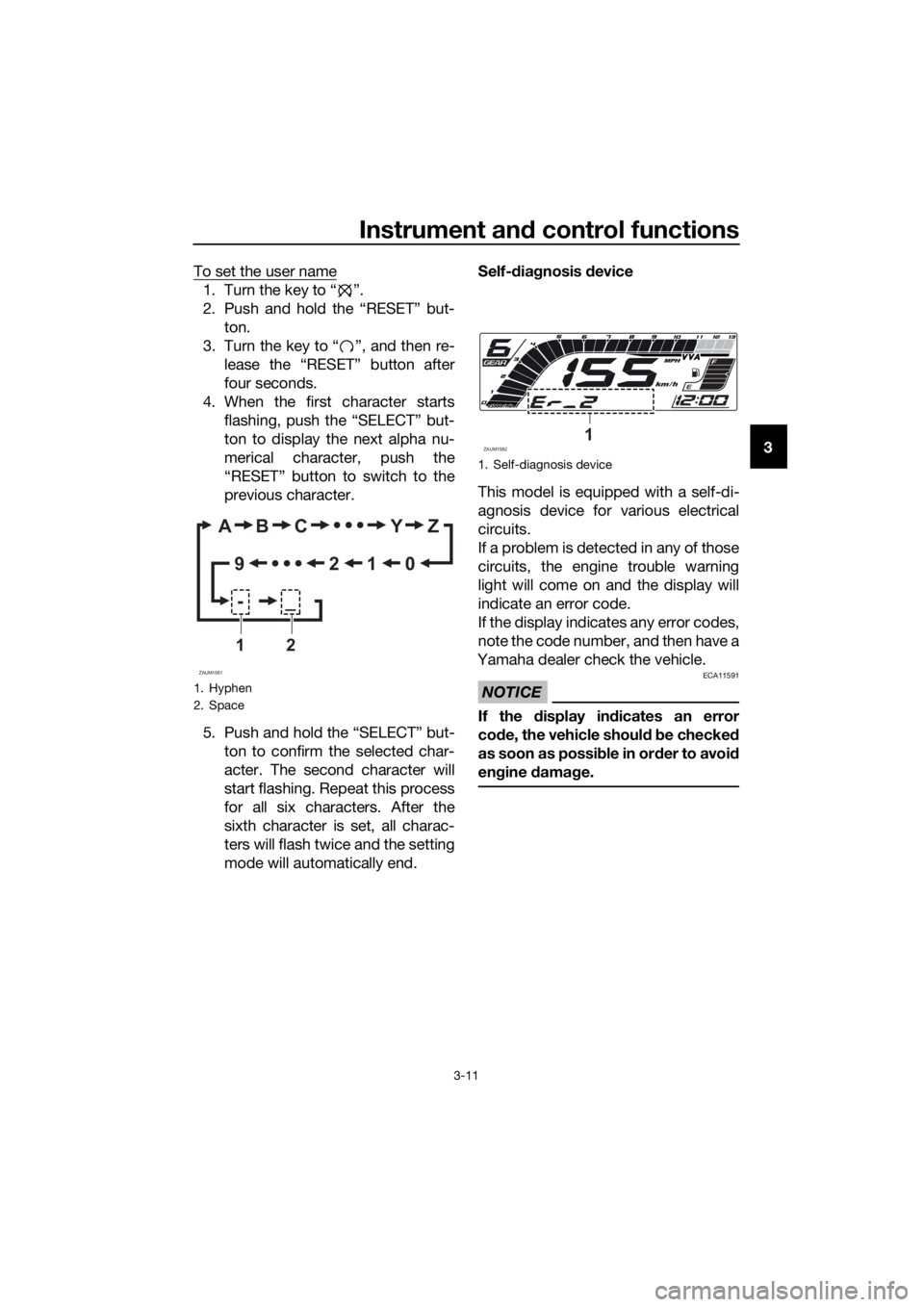
4. When the first character starts
flashing, push the “SELECT” but-
ton to display the next alpha nu-
merical character, push the
“RESET” button to switch to the
previous character.
5. Push and hold the “SELECT” but-
ton to confirm the selected char-
acter. The second character will
start flashing. Repeat this process
for all six characters. After the
sixth character is set, all charac-
ters will flash twice and the setting
mode will automatically end.Self-diagnosis device
This model is equipped with a self-di-
agnosis device for various electrical
circuits.
If a problem is detected in any of those
circuits, the engine trouble warning
light will come on and the display will
indicate an error code.
If the display indicates any error codes,
note the code number, and then have a
Yamaha dealer check the vehicle.
NOTICE
ECA11591
If the display indicates an error
code, the vehicle should be checked
as soon as possible in order to avoid
engine damage.
1. Hyphen
2. Space
ZAUM1581
AB C Y Z
0 1 2 9
-_
12
1. Self-diagnosis device
ZAUM15821
UB6GE0E0.book Page 11 Wednesday, August 28, 2019 11:11 AM
Page 29 of 96
Instrument and control functions
3-15
3
EAU63040
ABS
The Yamaha ABS (Anti-lock Brake
System) features a dual electronic con-
trol system, which acts on the front and
rear brakes independently.
Operate the brakes with ABS as you
would conventional brakes. If the ABS
is activated, a pulsating sensation may
be felt at the brake lever or brake ped-
al. In this situation, continue to apply
the brakes and let the ABS work; do
not “pump” the brakes as this will re-
duce braking effectiveness.
WARNING
EWA16051
Always keep a sufficient distance
from the vehicle ahead to match the
riding speed even with ABS.
The ABS performs best with
long braking distances.
On certain surfaces, such as
rough or gravel roads, the brak-
ing distance may be longer with
the ABS than without.
The ABS is monitored by an ECU,
which will revert the system to conven-
tional braking if a malfunction occurs.
TIP
The ABS performs a self-diagno-
sis test each time the vehicle first
starts off after the key is turned to
“ON” and the vehicle has traveled
at a speed of 10 km/h (6 mi/h) or
higher. During this test, a “click-
ing” noise can be heard from the
hydraulic control unit, and if the
brake lever or brake pedal is even
slightly applied, a vibration can be
felt at the lever and pedal, but
these do not indicate a malfunc-
tion.This ABS has a test mode which
allows the owner to experience
the pulsation at the brake lever or
brake pedal when the ABS is op-
erating. However, special tools are
required, so please consult your
Yamaha dealer.
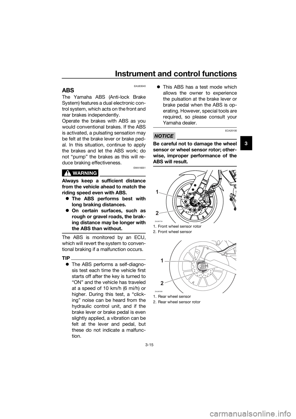
NOTICE
ECA20100
Be careful not to damage the wheel
sensor or wheel sensor rotor; other-
wise, improper performance of the
ABS will result.
1. Front wheel sensor rotor
2. Front wheel sensor
1. Rear wheel sensor
2. Rear wheel sensor rotor
ZAUM1734
1
2
ZAUM1590
1
2
UB6GE0E0.book Page 15 Wednesday, August 28, 2019 11:11 AM
Page 30 of 96

Instrument and control functions
3-16
3
EAU13076
Fuel tank cap
To open the fuel tank cap
Open the fuel tank cap lock cover, in-
sert the key into the lock, and then turn
it 1/4 turn clockwise. The lock will be
released and the fuel tank cap can be
opened.
To close the fuel tank cap
With the key still inserted in the lock,
push down the fuel tank cap. Turn the
key 1/4 turn counterclockwise, remove
it, and then close the lock cover.
TIP
The fuel tank cap cannot be closed un-
less the key is in the lock. In addition,
the key cannot be removed if the cap is
not properly closed and locked.
WARNING
EWA11092
Make sure that the fuel tank cap is
properly closed after filling fuel.
Leaking fuel is a fire hazard.
EAU13213
Fuel
Make sure there is sufficient gasoline in
the tank.
WARNING
EWA10882
Gasoline and gasoline vapors are
extremely flammable. To avoid fires
and explosions and to reduce the
risk of injury when refueling, follow
these instructions.
1. Before refueling, turn off the en-
gine and be sure that no one is sit-
ting on the vehicle. Never refuel
while smoking, or while in the vi-
cinity of sparks, open flames, or
other sources of ignition such as
the pilot lights of water heaters
and clothes dryers.
2. Do not overfill the fuel tank. Stop
filling when the fuel reaches the
bottom of the filler tube. Because
fuel expands when it heats up,
heat from the engine or the sun
can cause fuel to spill out of the
fuel tank.
3. Wipe up any spilled fuel immedi-
ately. NOTICE: Immediately
wipe off spilled fuel with a clean,1. Fuel tank cap lock cover
2. Unlock.
1
2
1. Fuel tank filler tube
2. Maximum fuel level
1
2
UB6GE0E0.book Page 16 Wednesday, August 28, 2019 11:11 AM