stop start YAMAHA MT-125 2020 Owners Manual
[x] Cancel search | Manufacturer: YAMAHA, Model Year: 2020, Model line: MT-125, Model: YAMAHA MT-125 2020Pages: 96, PDF Size: 8.36 MB
Page 18 of 96
Instrument and control functions
3-4
3
EAUM4010
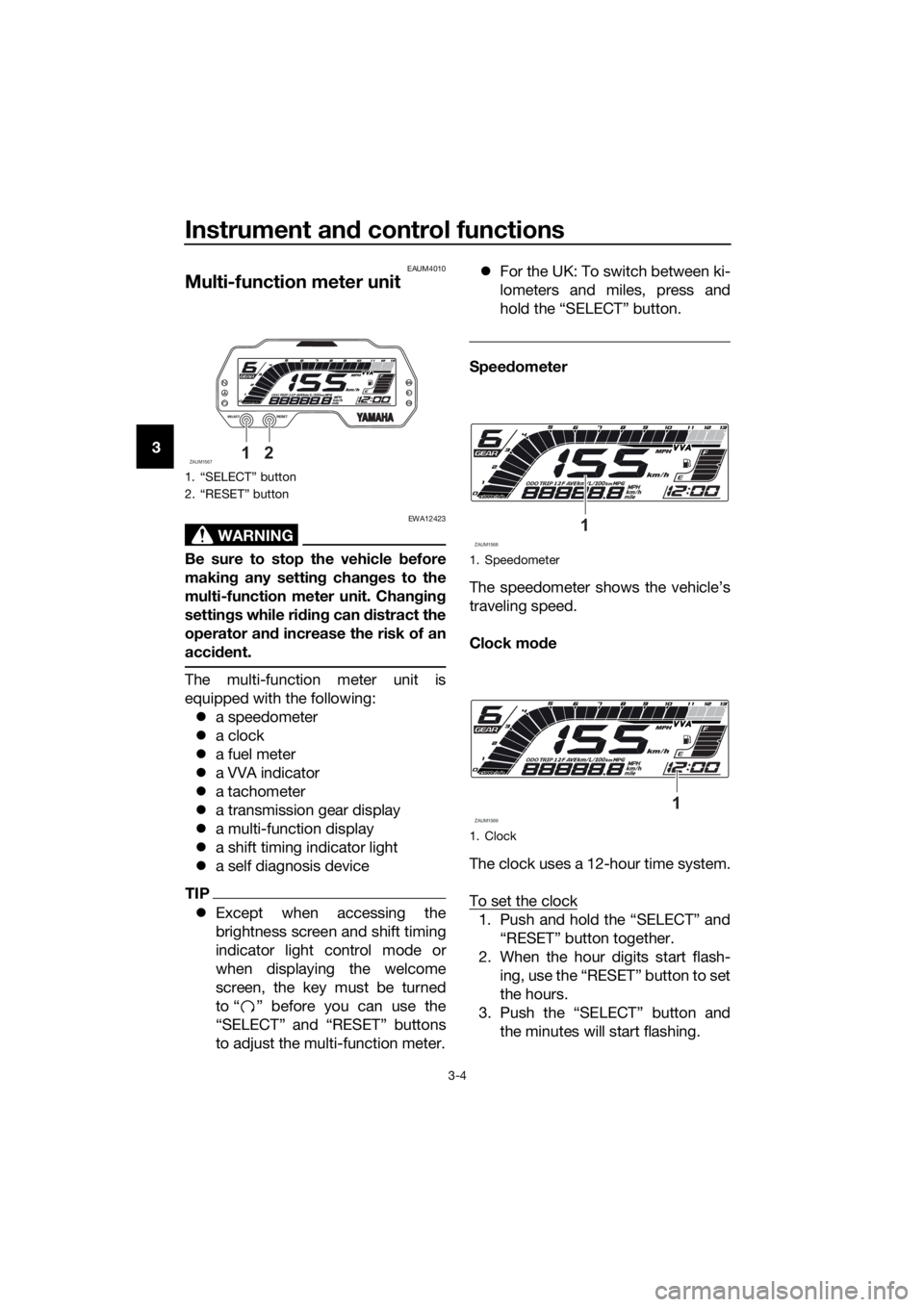
Multi-function meter unit
WARNING
EWA12423
Be sure to stop the vehicle before
making any setting changes to the
multi-function meter unit. Changing
settings while riding can distract the
operator and increase the risk of an
accident.
The multi-function meter unit is
equipped with the following:
a speedometer
a clock
a fuel meter
a VVA indicator
a tachometer
a transmission gear display
a multi-function display
a shift timing indicator light
a self diagnosis device
TIP
Except when accessing the
brightness screen and shift timing
indicator light control mode or
when displaying the welcome
screen, the key must be turned
to “ ” before you can use the
“SELECT” and “RESET” buttons
to adjust the multi-function meter.For the UK: To switch between ki-
lometers and miles, press and
hold the “SELECT” button.
Speedometer
The speedometer shows the vehicle’s
traveling speed.
Clock mode
The clock uses a 12-hour time system.
To set the clock
1. Push and hold the “SELECT” and
“RESET” button together.
2. When the hour digits start flash-
ing, use the “RESET” button to set
the hours.
3. Push the “SELECT” button and
the minutes will start flashing.
1. “SELECT” button
2. “RESET” button
ZAUM156712
1. Speedometer
1. Clock
ZAUM15681
ZAUM15691
UB6GE0E0.book Page 4 Wednesday, August 28, 2019 11:11 AM
Page 26 of 96
Instrument and control functions
3-12
3
EAU1234M
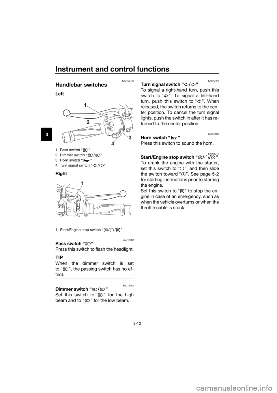
Handlebar switches
Left
Right
EAU12352Pass switch “ ”
Press this switch to flash the headlight.
TIP
When the dimmer switch is set
to Ž, the passing switch has no ef-
fect.
EAU12402Dimmer switch “ / ”
Set this switch to “ ” for the high
beam and to “ ” for the low beam.
EAU12461Turn signal switch “ / ”
To signal a right-hand turn, push this
switch to “ ”. To signal a left-hand
turn, push this switch to “ ”. When
released, the switch returns to the cen-
ter position. To cancel the turn signal
lights, push the switch in after it has re-
turned to the center position.
EAU12501Horn switch “ ”
Press this switch to sound the horn.
EAU68270Start/Engine stop switch “ / / ”
To crank the engine with the starter,
set this switch to “ ”, and then slide
the switch toward “ ”. See page 5-2
for starting instructions prior to starting
the engine.
Set this switch to “ ” to stop the en-
gine in case of an emergency, such as
when the vehicle overturns or when the
throttle cable is stuck.
1. Pass switch “ ”
2. Dimmer switch “ / ”
3. Horn switch “ ”
4. Turn signal switch “ / ”
1. Start/Engine stop switch “ / / ”
1
2
3
4
1
UB6GE0E0.book Page 12 Wednesday, August 28, 2019 11:11 AM
Page 35 of 96

Instrument and control functions
3-21
3
EAU83150
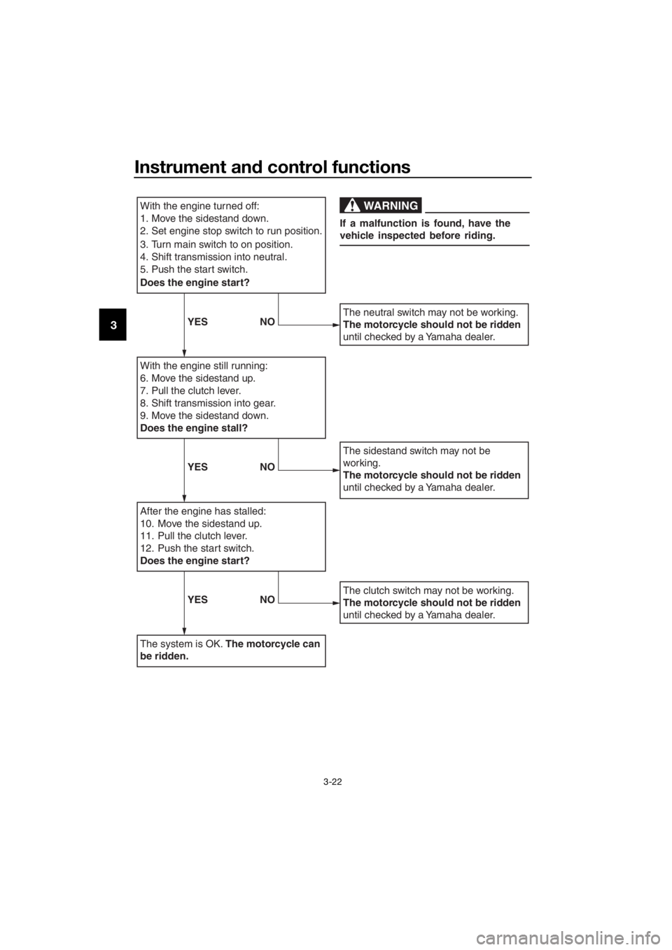
Ignition circuit cut-off system
This system prevents in-gear engine
starts unless the clutch lever is pulled
and the sidestand is up. Also, it will
stop the running engine should the
sidestand be lowered while the trans-
mission is in gear.
Periodically check the system via the
following procedure.
TIP
This check is most reliable if per-
formed with a warmed-up engine.
See pages 3-1 and 3-12 for switch
operation information.
UB6GE0E0.book Page 21 Wednesday, August 28, 2019 11:11 AM
Page 36 of 96
Instrument and control functions
3-22
3
With the engine turned off:
1. Move the sidestand down.
2.Set engine stop switch to run position.
3. Turn main switch to on position.
4.Shift transmission into neutral.
5. Push the start switch.
Does the engine start?
With the engine still running:
6. Move the sidestand up.
7. Pull the clutch lever.
8.Shift transmission into gear.
9. Move the sidestand down.
Does the engine stall?
After the engine has stalled:
10. Move the sidestand up.
11. Pull the clutch lever.
12. Push the start switch.
Does the engine start?
The system is OK. The motorcycle can
be ridden.
The neutral switch may not be working.
The motorcycle should not be ridden
until checked by a Yamaha dealer.
The sidestand switch may not be
working.
The motorcycle should not be ridden
until checked by a Yamaha dealer.
The clutch switch may not be working.
The motorcycle should not be ridden
until checked by a Yamaha dealer.
WARNING
If a malfunction is found, have the
vehicle inspected before riding.
YES NO
YES NO
YES NO
UB6GE0E0.book Page 22 Wednesday, August 28, 2019 11:11 AM
Page 40 of 96
Operation and important riding points
5-2
51000 km (600 mi) and beyond
The vehicle can now be operated nor-
mally.
NOTICE
ECA10311
Keep the engine speed out of
the tachometer red zone.
If any engine trouble should oc-
cur during the engine break-in
period, immediately have a
Yamaha dealer check the vehi-
cle.
EAU86690
Starting the engine
The ignition circuit cut-off system will
enable starting when:
the transmission is in the neutral
position or
the transmission is in gear, the
sidestand is up, and the clutch le-
ver is pulled.
To start the engine
1. Turn the main switch on and set
the engine stop switch to the run
position.
2. Confirm the indicator and warning
light(s) come on for a few sec-
onds, and the go off. (See page
3-2.)
TIP
Do not start the engine if the en-
gine trouble warning light remains
on.
The ABS warning light should
come on and stay on until the ve-
hicle reaches a speed of 10 km/h
(6 mi/h).
NOTICE
ECA24110
If a warning or indicator light does
not work as described above, have a
Yamaha dealer check the vehicle.
3. Shift the transmission into the
neutral position.
4. Start the engine by pushing the
start switch.
5. Release the start switch when the
engine starts, or after 5 seconds.
Wait 10 seconds before pressing
the switch again to allow battery
voltage to restore.
UB6GE0E0.book Page 2 Wednesday, August 28, 2019 11:11 AM
Page 41 of 96

Operation and important riding points
5-3
5
NOTICE
ECA11043
For maximum engine life, never ac-
celerate hard when the engine is
cold!
EAU45312
TIP
This model is equipped with a lean an-
gle sensor to stop the engine in case of
a turnover. In this case, turn the main
switch off and then on. Failing to do so
will prevent the engine from starting
even though the engine will crank
when pushing the start switch.
UB6GE0E0.book Page 3 Wednesday, August 28, 2019 11:11 AM
Page 42 of 96
Operation and important riding points
5-4
5
EAU16674
Shifting
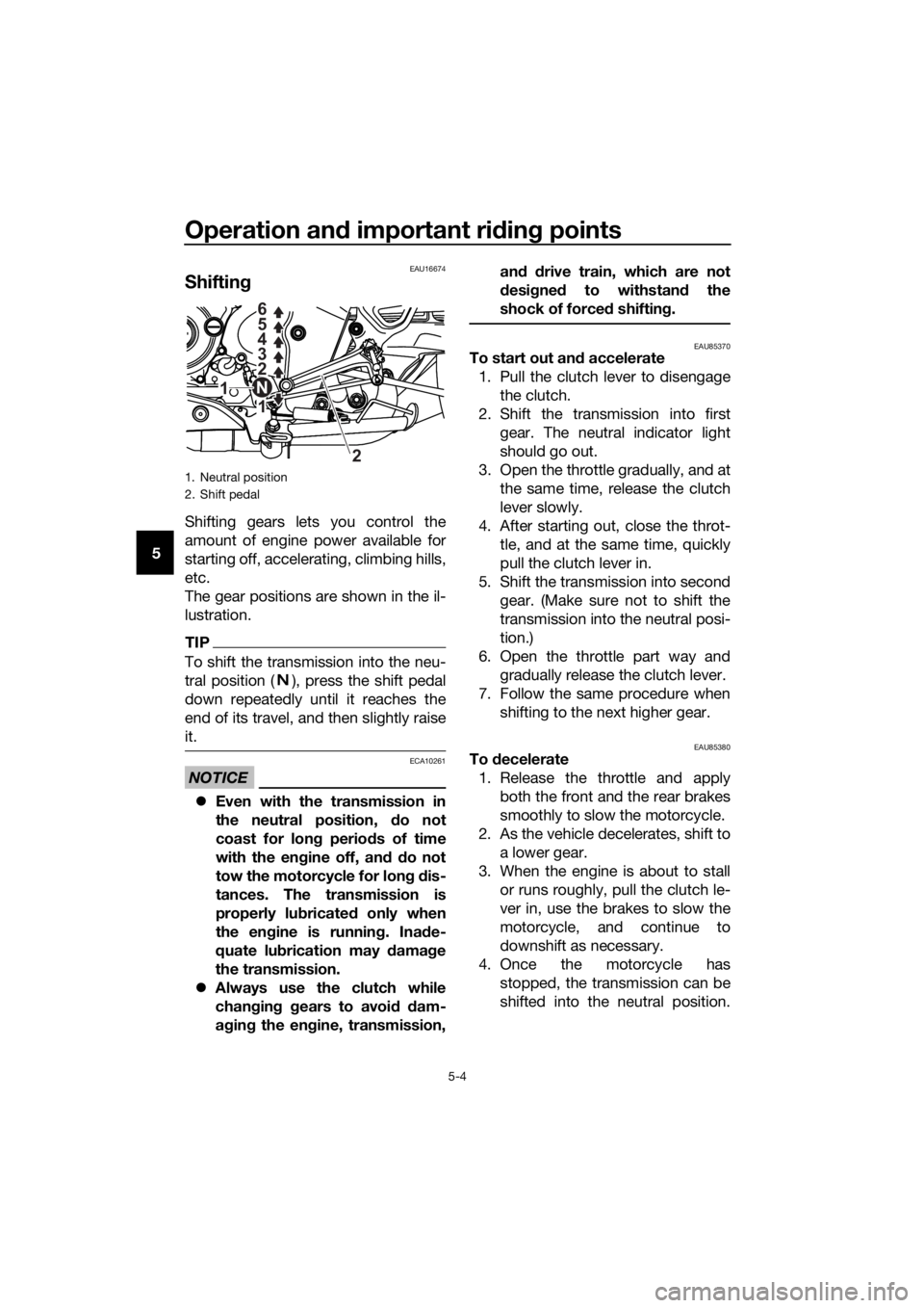
Shifting gears lets you control the
amount of engine power available for
starting off, accelerating, climbing hills,
etc.
The gear positions are shown in the il-
lustration.
TIP
To shift the transmission into the neu-
tral position ( ), press the shift pedal
down repeatedly until it reaches the
end of its travel, and then slightly raise
it.
NOTICE
ECA10261
Even with the transmission in
the neutral position, do not
coast for long periods of time
with the engine off, and do not
tow the motorcycle for long dis-
tances. The transmission is
properly lubricated only when
the engine is running. Inade-
quate lubrication may damage
the transmission.
Always use the clutch while
changing gears to avoid dam-
aging the engine, transmission,and drive train, which are not
designed to withstand the
shock of forced shifting.
EAU85370To start out and accelerate
1. Pull the clutch lever to disengage
the clutch.
2. Shift the transmission into first
gear. The neutral indicator light
should go out.
3. Open the throttle gradually, and at
the same time, release the clutch
lever slowly.
4. After starting out, close the throt-
tle, and at the same time, quickly
pull the clutch lever in.
5. Shift the transmission into second
gear. (Make sure not to shift the
transmission into the neutral posi-
tion.)
6. Open the throttle part way and
gradually release the clutch lever.
7. Follow the same procedure when
shifting to the next higher gear.
EAU85380To decelerate
1. Release the throttle and apply
both the front and the rear brakes
smoothly to slow the motorcycle.
2. As the vehicle decelerates, shift to
a lower gear.
3. When the engine is about to stall
or runs roughly, pull the clutch le-
ver in, use the brakes to slow the
motorcycle, and continue to
downshift as necessary.
4. Once the motorcycle has
stopped, the transmission can be
shifted into the neutral position.
1. Neutral position
2. Shift pedal
1 2 3 4 5
6
1
2 N
UB6GE0E0.book Page 4 Wednesday, August 28, 2019 11:11 AM
Page 81 of 96
Periodic maintenance and adjustment
6-37
6
EAU86430Engine overheating
WARNING
EWAT1041
Do not remove the radiator cap when the engine and radiator are hot.
Scalding hot fluid and steam may be blown out under pressure, which
could cause serious injury. Be sure to wait until the engine has cooled.
Place a thick rag, like a towel, over the radiator cap, and then slowly ro-
tate the cap counterclockwise to the detent to allow any residual pres-
sure to escape. When the hissing sound has stopped, press down on the
cap while turning it counterclockwise, and then remove the cap.
TIP
If coolant is not available, tap water can be temporarily used instead, provided
that it is changed to the recommended coolant as soon as possible.
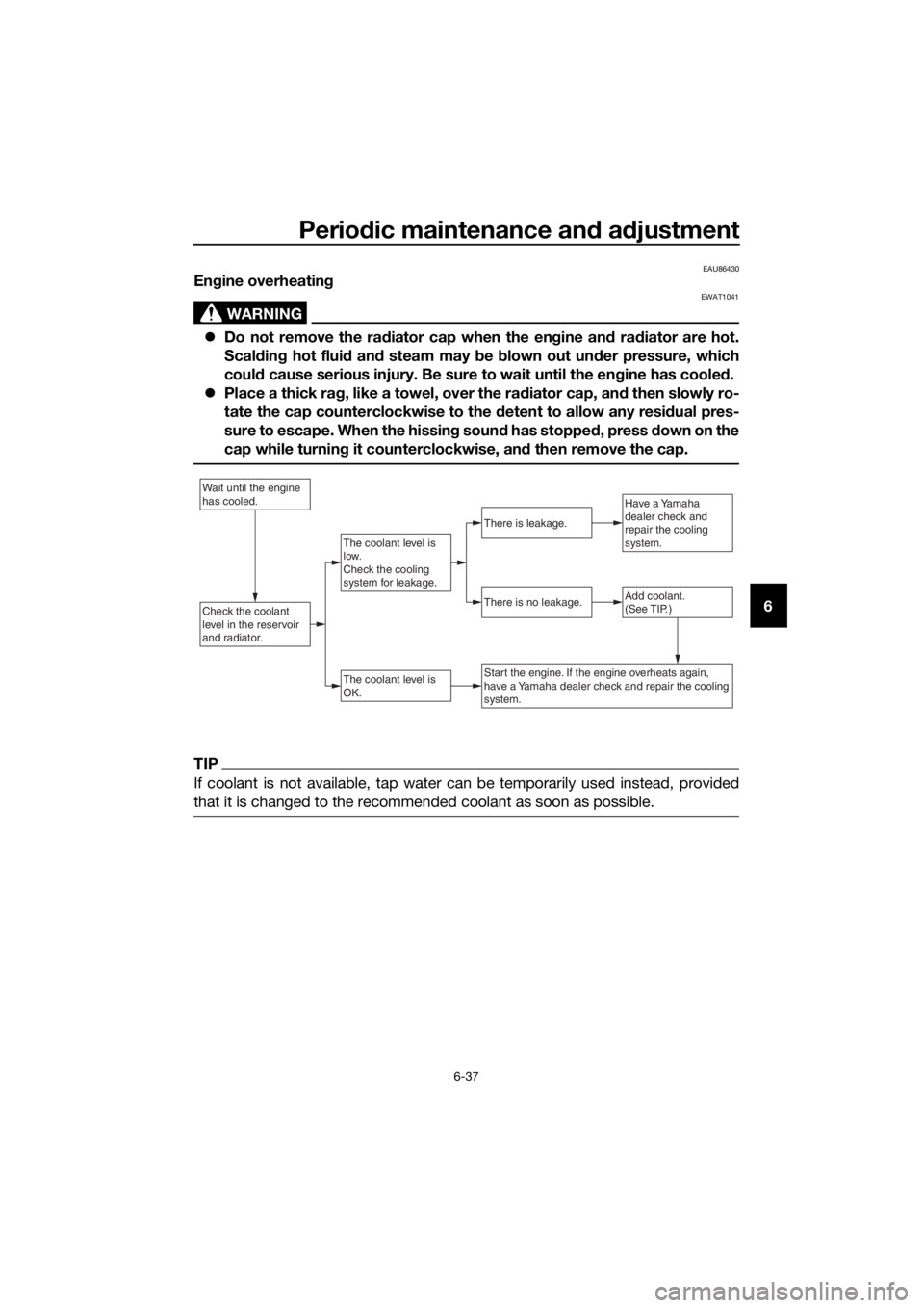
Wait until the engine
has cooled.
Check the coolant
level in the reservoir
and radiator.Add coolant.
(See TIP.)
The coolant level is
OK.
There is no leakage.
There is leakage.
The coolant level is
low.
Check the cooling
system for leakage.
Have a Yamaha
dealer check and
repair the cooling
system.
Start the engine. If the engine overheats again,
have a Yamaha dealer check and repair the cooling
system.
UB6GE0E0.book Page 37 Wednesday, August 28, 2019 11:11 AM
Page 92 of 96

10-1
10
Index
A
ABS ....................................................... 3-15
ABS warning light ................................... 3-3
Air filter element and check hose,
replacing and cleaning ....................... 6-13
B
Battery .................................................. 6-30
Brake and clutch levers, checking and
lubricating ........................................... 6-27
Brake and shift pedals, checking and
lubricating ........................................... 6-26
Brake fluid, changing ............................ 6-23
Brake fluid level, checking .................... 6-22
Brake lever ............................................ 3-14
Brake light switches.............................. 6-20
Brake pedal........................................... 3-14
Brake pedal free play, adjusting ........... 6-20
C
Cables, checking and lubricating ......... 6-25
Care ........................................................ 7-1
Catalytic converter ................................ 3-18
Clutch lever ........................................... 3-13
Clutch lever free play, adjusting ........... 6-18
Coolant ................................................. 6-11
Coolant temperature warning light ......... 3-2
Cowlings, removing and installing .......... 6-7
D
Data recording, vehicle ........................... 9-3
Diagnostic connectors ............................ 9-2
Dimmer switch ...................................... 3-12
Drive chain, cleaning and lubricating .... 6-25
Drive chain slack................................... 6-23
E
Engine break-in....................................... 5-1
Engine idling speed .............................. 6-13
Engine oil and oil filter element ............... 6-8
Engine overheating ............................... 6-37
Engine serial number .............................. 9-1
Engine trouble warning light ................... 3-3
F
Front and rear brake pads, checking.... 6-21
Front brake lever free play, checking ... 6-19
Front fork, checking .............................. 6-28
Fuel ....................................................... 3-16
Fuel consumption, tips for reducing ....... 5-5
Fuel tank cap ........................................ 3-16
Fuel tank overflow hose ........................ 3-18
Fuses, replacing.................................... 6-31
H
Handlebar switches .............................. 3-12Helmet holder ....................................... 3-20
High beam indicator light ....................... 3-2
Horn switch .......................................... 3-12
I
Identification numbers ............................ 9-1
Ignition circuit cut-off system............... 3-21
Indicator lights and warning lights ......... 3-2
L
License plate light bulb, replacing........ 6-34
M
Main switch/steering lock....................... 3-1
Maintenance and lubrication, periodic ... 6-4
Maintenance, emission control
system.................................................. 6-3
Matte color, caution ............................... 7-1
Model label ............................................. 9-1
Multi-function meter unit ........................ 3-4
N
Neutral indicator light ............................. 3-2
P
Parking ................................................... 5-6
Part locations ......................................... 2-1
Pass switch .......................................... 3-12
S
Safety information .................................. 1-1
Seat ...................................................... 3-19
Shifting ................................................... 5-4
Shift light ................................................ 3-3
Shift pedal ............................................ 3-13
Sidestand ............................................. 3-20
Sidestand, checking and lubricating .... 6-27
Spark plug, checking ............................. 6-7
Specifications ......................................... 8-1
Start/Engine stop switch ...................... 3-12
Starting the engine ................................. 5-2
Steering, checking................................ 6-29
Storage ................................................... 7-4
Supporting the motorcycle................... 6-34
Swingarm pivots, lubricating ................ 6-28
T
Tail/brake light ...................................... 6-33
Throttle grip and cable, checking and
lubricating .......................................... 6-26
Throttle grip free play, adjusting........... 6-14
Tires ...................................................... 6-15
Tool kit.................................................... 6-2
Troubleshooting ................................... 6-35
Troubleshooting chart .......................... 6-36
Turn signal indicator light ....................... 3-2
Turn signal light bulb, replacing ........... 6-33
UB6GE0E0.book Page 1 Wednesday, August 28, 2019 11:11 AM