stop start YAMAHA MT-125 2021 Owners Manual
[x] Cancel search | Manufacturer: YAMAHA, Model Year: 2021, Model line: MT-125, Model: YAMAHA MT-125 2021Pages: 94, PDF Size: 7.08 MB
Page 27 of 94

Instrument and control functions
3-12
3
for all six characters. After the
sixth character is set, all charac-
ters will flash twice and the setting
mode will automatically end.
Self-d iagnostic device
This model is equipped with a self-di-
agnostic device for various electrical
circuits.
If a problem is detected in any of those
circuits, the engine trouble warning
light will come on and the display will
indicate an error code.
If the display indicates any error codes,
note the code number, and then have
a Yamaha dealer check the vehicle.
NOTICE
ECA11591
If the display in dicates an error
co de, the vehicle shoul d b e checked
as soon as possi ble in or der to avoi d
en gine damag e.
EAU1234R
Handle bar switchesLeft
Ri ght
1. Self-diagnostic deviceZAUM1582
1
1. Pass switch “ ”
2. Dimmer switch “ / ”
3. Horn switch “ ”
4. Turn signal switch “ / ”
1. Start/Engine stop switch “ / / ”
12
3
4
1
UB6GE1E0.book Page 12 Thursday, July 30, 2020 1:08 PM
Page 28 of 94
Instrument and control functions
3-13
3
EAU12352
Pass switch “ ”
Press this switch to flash the headlight.TIPWhen the dimmer switch is set
to “ ”, the passing switch has no ef-
fect.
EAU12402
Dimmer switch “ / ”
Set this switch to “ ” for the high
beam and to “ ” for the low beam.
EAU12461
Turn si gnal switch “ / ”
To signal a right-hand turn, push this
switch to “ ”. To signal a left-hand
turn, push this switch to “ ”. When
released, the switch returns to the cen-
ter position. To cancel the turn signal
lights, push the switch in after it has re-
turned to the center position.
EAU12501
Horn switch “ ”
Press this switch to sound the horn.
EAU68271
Start/En gine stop switch “ / / ”
To crank the engine with the starter,
set this switch to “ ”, and then slide
the switch toward “ ”. See page 5-2
for starting instructions prior to starting
the engine.
Set this switch to “ ” to stop the en-
gine in case of an emergency, such as
when the vehicle overturns or when the
throttle cable is stuck.
EAU12823
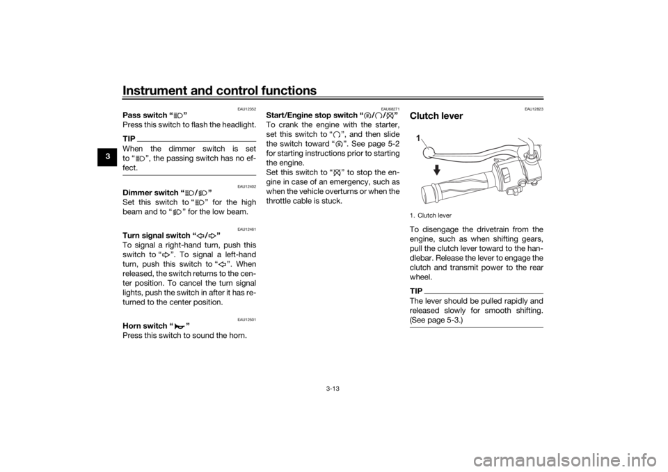
Clutch leverTo disengage the drivetrain from the
engine, such as when shifting gears,
pull the clutch lever toward to the han-
dlebar. Release the lever to engage the
clutch and transmit power to the rear
wheel.TIPThe lever should be pulled rapidly and
released slowly for smooth shifting.
(See page 5-3.)1. Clutch lever1
UB6GE1E0.book Page 13 Thursday, July 30, 2020 1:08 PM
Page 36 of 94
Instrument and control functions
3-21
3 this system reg
ularly and have a
Yamaha dealer repair it if it does not
function properly.
EAU44895
I g nition circuit cut-off systemThis system prevents in-gear engine
starts unless the clutch lever is pulled
and the sidestand is up. Also, it will
stop the running engine should the
sidestand be lowered while the trans-
mission is in gear.
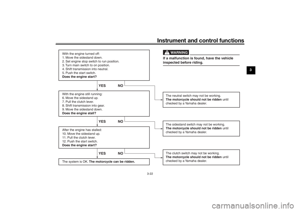
Periodically check the system via the
following procedure.TIP This check is most reliable if per-
formed with a warmed-up engine.
See pages 3-1 and 3-12 for switch
operation information.
UB6GE1E0.book Page 21 Thursday, July 30, 2020 1:08 PM
Page 37 of 94
Instrument and control functions
3-22
3
With the engine turned off:
1. Move the sidestand down.
2. Set engine stop switch to run position.
3. Turn main switch to on position.
4. Shift transmission into neutral.
5. Push the start switch.
Does the engine start?
With the engine still running:
6. Move the sidestand up.
7. Pull the clutch lever.
8. Shift transmission into gear.
9. Move the sidestand down.
Does the engine stall?
After the engine has stalled:
10. Move the sidestand up.
11. Pull the clutch lever.
12. Push the start switch.
Does the engine start?
The system is OK. The motorcycle can be ridden.
YES NO YES NO YES NO
The neutral switch may not be working.
The motorcycle should not be ridden until
checked by a Yamaha dealer.
The clutch switch may not be working.
The motorcycle should not be ridden until
checked by a Yamaha dealer.The sidestand switch may not be working.
The motorcycle should not be ridden until
checked by a Yamaha dealer.If a malfunction is found, have the vehicle
inspected before riding.
WARNING
UB6GE1E0.book Page 22 Thursday, July 30, 2020 1:08 PM
Page 42 of 94
Operation and important rid ing points
5-2
5
EAU86690
Startin g the eng ineThe ignition circuit cut-off system will
enable starting when:
the transmission is in the neutral
position or
the transmission is in gear, the
sidestand is up, and the clutch le-
ver is pulled.
To start the engine1. Turn the main switch on and set the engine stop switch to the run
position.
2. Confirm the indicator and warning light(s) come on for a few sec-
onds, and the go off. (See page
3-2.)TIPDo not start the engine if the en-
gine trouble warning light remains
on.
The ABS warning light should
come on and stay on until the ve-
hicle reaches a speed of 10 km/h
(6 mi/h).
NOTICE
ECA24110
If a warnin g or in dicator li ght does
not work as d escribed a bove, have a
Yamaha dealer check the vehicle.3. Shift the transmission into the
neutral position.
4. Start the engine by pushing the start switch.
5. Release the start switch when the engine starts, or after 5 seconds.
Wait 10 seconds before pressing
the switch again to allow battery
voltage to restore.NOTICE
ECA11043
For maximum en gine life, never ac-
celerate har d when the en gine is
col d!
EAU45312
TIPThis model is equipped with a lean an-
gle sensor to stop the engine in case of
a turnover. In this case, turn the main
switch off and then on. Failing to do so
will prevent the engine from starting
even though the engine will crank
when pushing the start switch.
UB6GE1E0.book Page 2 Thursday, July 30, 2020 1:08 PM
Page 43 of 94
Operation and important ri din g points
5-3
5
EAU16674
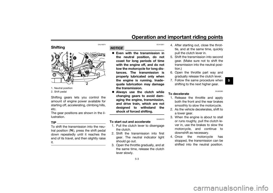
Shiftin gShifting gears lets you control the
amount of engine power available for
starting off, accelerating, climbing hills,
etc.
The gear positions are shown in the il-
lustration.TIPTo shift the transmission into the neu-
tral position ( ), press the shift pedal
down repeatedly until it reaches the
end of its travel, and then slightly raise
it.
NOTICE
ECA10261
Even with the transmission in
the neutral position, do not
coast for lon g period s of time
with the eng ine off, and d o not
tow the motorcycle for lon g d is-
tances. The transmission is
properly lu bricated only when
the en gine is runnin g. Ina de-
quate lu brication may damag e
the transmission.
Always use the clutch while
chan gin g g ears to avoi d d am-
a g in g the en gine, transmission,
an d d rive train, which are not
d esi gne d to withstan d the
shock of forced shifting.
EAU85370
To start out an d accelerate
1. Pull the clutch lever to disengage the clutch.
2. Shift the transmission into first gear. The neutral indicator light
should go out.
3. Open the throttle gradually, and at the same time, release the clutch
lever slowly. 4. After starting out, close the throt-
tle, and at the same time, quickly
pull the clutch lever in.
5. Shift the transmission into second gear. (Make sure not to shift the
transmission into the neutral posi-
tion.)
6. Open the throttle part way and gradually release the clutch lever.
7. Follow the same procedure when shifting to the next higher gear.
EAU85380
To decelerate
1. Release the throttle and apply both the front and the rear brakes
smoothly to slow the motorcycle.
2. As the vehicle decelerates, shift to a lower gear.
3. When the engine is about to stall or runs roughly, pull the clutch le-
ver in, use the brakes to slow the
motorcycle, and continue to
downshift as necessary.
4. Once the motorcycle has stopped, the transmission can be
shifted into the neutral position.
1. Neutral position
2. Shift pedal
1 2 3 4 5
6
1
2
N
UB6GE1E0.book Page 3 Thursday, July 30, 2020 1:08 PM
Page 80 of 94

Periodic maintenance an d a djustment
6-36
6
EAU86420
En gine overheatin g
WARNING
EWAT1041
Do not remove the ra diator cap when the en gine an d ra diator are hot. Scal din g hot flui d an d steam may be
b lown out un der pressure, which coul d cause serious injury. Be sure to wait until the en gine has coole d.
Place a thick ra g, like a towel, over the ra diator cap, an d then slowly rotate the cap counterclockwise to the
d etent to allow any resi dual pressure to escape. When the hissin g soun d has stoppe d, press d own on the cap
while turnin g it counterclockwise, an d then remove the cap.TIPIf coolant is not available, tap water can be temporarily used instead, provided that it is changed to the recommended cool-
ant as soon as possible.
Wait until the
engine has cooled.
Check the coolant level in the
reservoir and radiator.
The coolant level
is OK.The coolant level is low.
Check the cooling system
for leakage.
Have a Yamaha dealer checkand repair the cooling system.Add coolant. (See TIP.)
Start the engine. If the engine overheats again,
have a
Yamaha dealer check
and repair the cooling system.
There is
leakage.
There is
no leakage.
UB6GE1E0.book Page 36 Thursday, July 30, 2020 1:08 PM
Page 90 of 94

10-1
10
IndexAABS ....................................................... 3-15
ABS warning light ................................... 3-3
Air filter element and check hose,
replacing and cleaning ....................... 6-14BBattery .................................................. 6-30
Brake and clutch levers, checking and lubricating ........................................... 6-27
Brake and shift pedals, checking and lubricating ........................................... 6-27
Brake fluid, changing ............................ 6-24
Brake fluid level, checking .................... 6-22
Brake lever ............................................ 3-14
Brake light switches.............................. 6-21
Brake pedal........................................... 3-14
Brake pedal free play, adjusting ........... 6-21CCables, checking and lubricating ......... 6-26
Canister................................................... 6-9
Care ........................................................ 7-1
Catalytic converter ................................ 3-19
Clutch lever ........................................... 3-13
Clutch lever free play, adjusting ........... 6-19
Coolant ................................................. 6-13
Coolant temperature warning light ......... 3-2
Cowlings, removing and installing .......... 6-8DData recording, vehicle ........................... 9-2
Diagnostic connector.............................. 9-2
Dimmer switch ...................................... 3-13
Drive chain, cleaning and lubricating .... 6-25
Drive chain slack................................... 6-24
EEngine break-in ...................................... 5-1
Engine idling speed .............................. 6-15
Engine oil and oil filter element ............ 6-10
Engine overheating ............................... 6-36
Engine serial number .............................. 9-1FFront and rear brake pads, checking ... 6-22
Front brake lever free play, checking ... 6-20
Front fork, checking ............................. 6-29
Fuel ....................................................... 3-16
Fuel consumption, tips for reducing ...... 5-4
Fuel tank breather hose and overflow hose ................................................... 3-18
Fuel tank cap ........................................ 3-16
Fuses, replacing ................................... 6-31HHandlebar switches .............................. 3-12
Helmet holder ....................................... 3-20
High beam indicator light ....................... 3-2
Horn switch .......................................... 3-13IIdentification numbers ............................ 9-1
Ignition circuit cut-off system ............... 3-21
Indicator lights and warning lights ......... 3-2LLicense plate light bulb, replacing........ 6-33MMain switch/steering lock....................... 3-1
Maintenance and lubrication, periodic ... 6-4
Maintenance, emission control system.................................................. 6-3
Malfunction indicator light (MIL) ............. 3-3
Matte color, caution ............................... 7-1 Model label .............................................9-1
Multi-function meter unit .........................3-4
NNeutral indicator light ..............................3-2PParking ....................................................5-4
Part locations ..........................................2-1
Pass switch ...........................................3-13RRear suspension, lubricating ................6-28SSafety information ...................................1-1
Seat .......................................................3-19
Shifting ....................................................5-3
Shift light .................................................3-3
Shift pedal .............................................3-14
Sidestand ..............................................3-20
Sidestand, checking and lubricating.....6-28
Spark plug, checking ..............................6-8
Specifications .........................................8-1
Start/Engine stop switch .......................3-13
Starting the engine ..................................5-2
Steering, checking ................................6-29
Storage ...................................................7-3
Supporting the motorcycle ...................6-34TTail/brake light ......................................6-32
Throttle grip and cable, checking and
lubricating ...........................................6-26
Throttle grip free play, adjusting ...........6-16
Tires ......................................................6-17
Tool kit ....................................................6-2
Troubleshooting ....................................6-34
Troubleshooting chart ...........................6-35
UB6GE1E0.book Page 1 Thursday, July 30, 2020 1:08 PM