key YAMAHA MT-25 2016 Owners Manual
[x] Cancel search | Manufacturer: YAMAHA, Model Year: 2016, Model line: MT-25, Model: YAMAHA MT-25 2016Pages: 96, PDF Size: 5.16 MB
Page 4 of 96
Important manual information
EAU10134
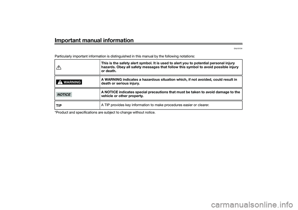
Particularly important information is distinguished in this manual by the following notations:
*Product and specifications are subject to change without notice.This is the safety alert symbol. It is used to alert you to potential personal injury
hazards. Obey all safety messages that follow this symbol to avoid possible injury
or death.
A WARNING indicates a hazardous situation which, if not avoided, could result in
death or serious injury.
A NOTICE indicates special precautions that must be taken to avoid damage to the
vehicle or other property.
A TIP provides key information to make procedures easier or clearer.
WARNING
NOTICETIP
UB04E0E0.book Page 1 Wednesday, September 2, 2015 3:51 PM
Page 16 of 96
Instrument and control functions
3-1
3
EAU10462
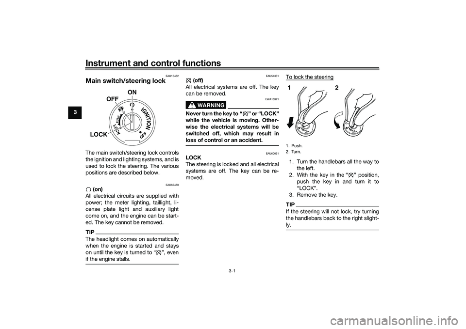
Main switch/steering lockThe main switch/steering lock controls
the ignition and lighting systems, and is
used to lock the steering. The various
positions are described below.
EAU62480
(on)
All electrical circuits are supplied with
power; the meter lighting, taillight, li-
cense plate light and auxiliary light
come on, and the engine can be start-
ed. The key cannot be removed.
TIPThe headlight comes on automatically
when the engine is started and stays
on until the key is turned to Ž, even
if the engine stalls.
EAU54301
(off)
All electrical systems are off. The key
can be removed.
WARNING
EWA16371
Never turn the key to “ ” or “LOCK”
while the vehicle is moving. Other-
wise the electrical systems will be
switched off, which may result in
loss of control or an accident.
EAU60861
LOCK
The steering is locked and all electrical
systems are off. The key can be re-
moved.To lock the steering
1. Turn the handlebars all the way to
the left.
2. With the key in the “ ” position,
push the key in and turn it to
“LOCK”.
3. Remove the key.TIPIf the steering will not lock, try turning
the handlebars back to the right slight-
ly.
ON
OFF
LOCK
1. Push.
2. Turn.12
UB04E0E0.book Page 1 Wednesday, September 2, 2015 3:51 PM
Page 17 of 96
Instrument and control functions
3-2
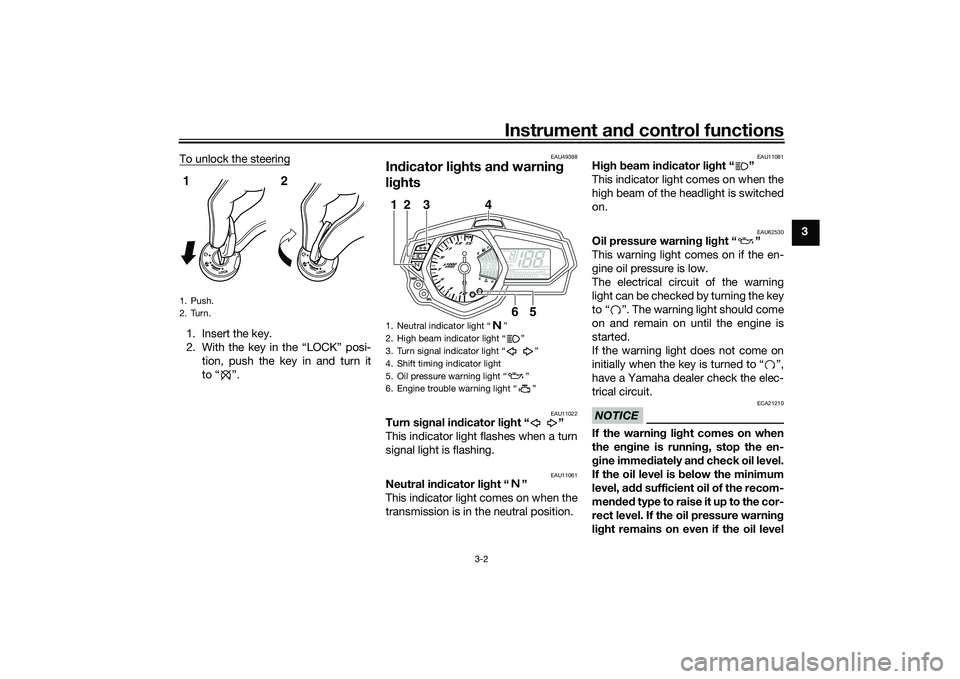
3 To unlock the steering
1. Insert the key.
2. With the key in the “LOCK” posi-
tion, push the key in and turn it
to “ ”.
EAU49398
Indicator lights and warning
lights
EAU11022
Turn signal indicator light “ ”
This indicator light flashes when a turn
signal light is flashing.
EAU11061
Neutral indicator light “ ”
This indicator light comes on when the
transmission is in the neutral position.
EAU11081
High beam indicator light “ ”
This indicator light comes on when the
high beam of the headlight is switched
on.
EAU62530
Oil pressure warning light “ ”
This warning light comes on if the en-
gine oil pressure is low.
The electrical circuit of the warning
light can be checked by turning the key
to “ ”. The warning light should come
on and remain on until the engine is
started.
If the warning light does not come on
initially when the key is turned to “ ”,
have a Yamaha dealer check the elec-
trical circuit.NOTICE
ECA21210
If the warning light comes on when
the engine is running, stop the en-
gine immediately and check oil level.
If the oil level is below the minimum
level, add sufficient oil of the recom-
mended t y p e t o r a i s e i t u p t o t h e c o r -
rect level. If the oil pressure warning
light remains on even if the oil level
1. Push.
2. Turn.12
1. Neutral indicator light Ž
2. High beam indicator light Ž
3. Turn signal indicator light Ž
4. Shift timing indicator light
5. Oil pressure warning light Ž
6. Engine trouble warning light Ž
6
5
3
1
2
4
UB04E0E0.book Page 2 Wednesday, September 2, 2015 3:51 PM
Page 18 of 96
Instrument and control functions
3-3
3is correct, immediately turn the en-
gine off and have a Yamaha dealer
check the vehicle.
TIPIf the warning light does not go off after
starting the engine, check the engine
oil level and add oil if necessary. (See
page 6-9.)
If the warning light remains on after
adding engine oil, have a Yamaha
dealer check the vehicle.
EAU62790
Engine trouble warning light “ ”
This warning light comes on or flashes
if a problem is detected in the electrical
circuit monitoring the engine. If this oc-
curs, have a Yamaha dealer check the
self-diagnosis system. (See page 3-10
for an explanation of the self-diagnosis
device.)
The electrical circuit of the warning
light can be checked by turning the key
to “ ”. The warning light should come
on for a few seconds, and then go off.If the warning light does not come on
initially when the key is turned to “ ”,
or if the warning light remains on, have
a Yamaha dealer check the electrical
circuit.
TIPThe engine trouble warning light will
come on while the start switch is
pushed, but this does not indicate a
malfunction.
EAU62470
Shift timing indicator light
This indicator light can be set to come
on and go off at the desired engine
speeds and is used to inform the rider
when it is time to shift to the next high-
er gear. (See page 3-8 for a more de-
tailed explanation of this indicator light
and on how to set it.)
The electrical circuit of the indicator
light can be checked by turning the key
to “ ”. The indicator light should
come on for a few seconds, and then
go off.If the indicator light does not come on
initially when the key is turned to “ ”,
or if the indicator light remains on, have
a Yamaha dealer check the electrical
circuit.
UB04E0E0.book Page 3 Wednesday, September 2, 2015 3:51 PM
Page 19 of 96

Instrument and control functions
3-4
3
EAU62765
Multi-function meter unit
WARNING
EWA12423
Be sure to stop the vehicle before
making any setting changes to the
multi-function meter unit. Changingsettings while riding can distract the
operator and increase the risk of an
accident.
The multi-function meter unit is
equipped with the following:
a speedometer
a tachometer
a clock
a fuel meter
a coolant temperature meter
a transmission gear display
a multi-function display
a shift timing indicator light
a self-diagnosis deviceTIPBe sure to turn the key to Ž before
except for setting the shift timing indi-
cator light control mode.Speedometer
The speedometer shows the vehicle’s
traveling speed.Tachometer
The tachometer allows the rider to
monitor the engine speed and keep it
within the ideal power range.
When the key is turned to “ ”, the ta-
chometer will sweep across the r/min
range and then return to zero r/min in
order to test the electrical circuit.
NOTICE
ECA10032
Do not operate the engine in the ta-
chometer red zone.
Red zone: 14000 r/min and above
1. “SEL” button
2. “RES” button
3. Tachometer
4. Fuel meter
5. Shift timing indicator light
6. Clock
7. Transmission gear display
8. Speedometer
9. Multi-function display
10.Coolant temperature meter
10
9
1
3
2
4
6
5
7
8
1. Tachometer
2. Tachometer red zone
12
UB04E0E0.book Page 4 Wednesday, September 2, 2015 3:51 PM
Page 20 of 96
Instrument and control functions
3-5
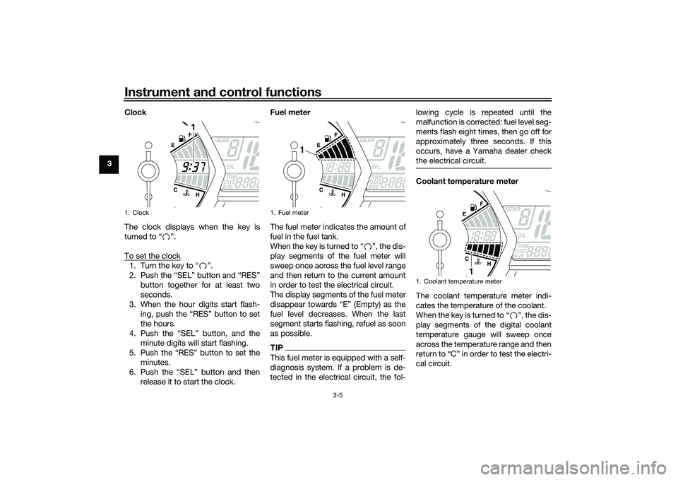
3Clock
The clock displays when the key is
turned to “ ”.
To set the clock
1. Turn the key to “ ”.
2. Push the “SEL” button and “RES”
button together for at least two
seconds.
3. When the hour digits start flash-
ing, push the “RES” button to set
the hours.
4. Push the “SEL” button, and the
minute digits will start flashing.
5. Push the “RES” button to set the
minutes.
6. Push the “SEL” button and then
release it to start the clock.Fuel meter
The fuel meter indicates the amount of
fuel in the fuel tank.
When the key is turned to “ ”, the dis-
play segments of the fuel meter will
sweep once across the fuel level range
and then return to the current amount
in order to test the electrical circuit.
The display segments of the fuel meter
disappear towards “E” (Empty) as the
fuel level decreases. When the last
segment starts flashing, refuel as soon
as possible.
TIPThis fuel meter is equipped with a self-
diagnosis system. If a problem is de-
tected in the electrical circuit, the fol-lowing cycle is repeated until the
malfunction is corrected: fuel level seg-
ments flash eight times, then go off for
approximately three seconds. If this
occurs, have a Yamaha dealer check
the electrical circuit.
Coolant temperature meter
The coolant temperature meter indi-
cates the temperature of the coolant.
When the key is turned to “ ”, the dis-
play segments of the digital coolant
temperature gauge will sweep once
across the temperature range and then
return to “C” in order to test the electri-
cal circuit.
1. Clock
1
1. Fuel meter
1
1. Coolant temperature meter
1
UB04E0E0.book Page 5 Wednesday, September 2, 2015 3:51 PM
Page 24 of 96
Instrument and control functions
3-9
3Brightness: this function allows
you to adjust the brightness of the
indicator light.
To adjust the shift timing indicator light
1. Turn the key to “ ”.
2. Push and hold the “SEL” button.
3. Turn the key to “ ”, and then re-
lease the “SEL” button after five
seconds. The shift timing indicator
light can now be adjusted.
To set the flashing pattern1. Push the “RES” button to select
one of the following flashing pat-
tern settings:
On: the indicator light stays
on when activated. (This set-
ting is selected when the indi-
cator light stays on.)
Flash: the indicator light
flashes when activated. (This
setting is selected when the
indicator light flashes four
times per second.)
Off: the indicator light is deac-
tivated; in other words, it
does not come on or flash.(This setting is selected when
the indicator light flashes
once every two seconds.)
2. Push the “SEL” button to confirm
the selected flashing pattern. The
shift timing indicator light changes
to the activation point setting
mode.
The tachometer will show the current
setting r/min for the activation point
and deactivation point setting modes.
To set the shift activation point
TIPThe shift timing indicator light activa-
tion point can be set between 7000
r/min and 15000 r/min. From 7000
r/min to 12000 r/min, the indicator light
can be set in increments of 500 r/min.
From 12000 r/min to 15000 r/min, the
indicator light can be set in increments
of 200 r/min.1.
the desired engine speed for acti-
vating the indicator light.2.
the selected engine speed. The
control mode changes to the de-
activation point setting mode.
To set the deactivation point
TIPThe shift timing indicator light de-
activation point can be set be-
tween 7000 r/min and 15000
r/min. From 7000 r/min to 12000
r/min, the indicator light can be set
in increments of 500 r/min. From
12000 r/min to 15000 r/min, the in-
dicator light can be set in incre-
ments of 200 r/min.
Be sure to set the deactivation
point to a higher engine speed
than for the activation point, other-
wise the shift timing indicator light
will not come on.1. Push the “RES” button to select
the desired engine speed for de-
activating the indicator light.
2. Push the “SEL” button to confirm
the selected engine speed. The
control mode changes to the
brightness setting mode.
UB04E0E0.book Page 9 Wednesday, September 2, 2015 3:51 PM
Page 26 of 96

Instrument and control functions
3-11
3
EAU12361
Pass switch “PASS”
Press this switch to flash the headlight.
EAU62540
Dimmer switch “ / ”
Set this switch to “ ” for the high
beam and to “ ” for the low beam.TIPWhen the switch is set to low beam,
only the right headlight bulb comes on.
When the switch is set to high beam,
both headlight bulbs come on.
EAU12461
Turn signal switch “ / ”
To signal a right-hand turn, push this
switch to “ ”. To signal a left-hand
turn, push this switch to “ ”. When
released, the switch returns to the cen-
ter position. To cancel the turn signal
lights, push the switch in after it has re-
turned to the center position.
EAU12501
Horn switch “ ”
Press this switch to sound the horn.
EAU12661
Engine stop switch “ / ”
Set this switch to “ ” before starting
the engine. Set this switch to “ ” to
stop the engine in case of an emergen-
cy, such as when the vehicle overturns
or when the throttle cable is stuck.
EAU12713
Start switch “ ”
Push this switch to crank the engine
with the starter. See page 5-1 for start-
ing instructions prior to starting the en-
gine.
EAU62500
The engine trouble warning light will
come on when the key is turned to “ ”
and the start switch is pushed, but this
does not indicate a malfunction.
EAU12822
Clutch leverThe clutch lever is located on the left
side of the handlebar. To disengage
the clutch, pull the lever toward the
handlebar grip. To engage the clutch,
release the lever. The lever should be
pulled rapidly and released slowly for
smooth clutch operation.
The clutch lever is equipped with a
clutch switch, which is part of the igni-
tion circuit cut-off system. (See page
3-20.)1. Clutch lever1
UB04E0E0.book Page 11 Wednesday, September 2, 2015 3:51 PM
Page 28 of 96
Instrument and control functions
3-13
3
EAU13075
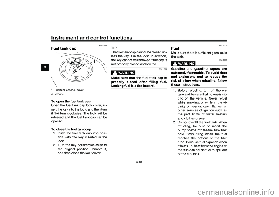
Fuel tank capTo open the fuel tank cap
Open the fuel tank cap lock cover, in-
sert the key into the lock, and then turn
it 1/4 turn clockwise. The lock will be
released and the fuel tank cap can be
opened.
To close the fuel tank cap
1. Push the fuel tank cap into posi-
tion with the key inserted in the
lock.
2. Turn the key counterclockwise to
the original position, remove it,
and then close the lock cover.
TIPThe fuel tank cap cannot be closed un-
less the key is in the lock. In addition,
the key cannot be removed if the cap is
not properly closed and locked.
WARNING
EWA11092
Make sure that the fuel tank cap is
properly closed after filling fuel.
Leaking fuel is a fire hazard.
EAU13222
FuelMake sure there is sufficient gasoline in
the tank.
WARNING
EWA10882
Gasoline and gasoline vapors are
extremely flammable. To avoid fires
and explosions and to reduce the
risk of injury when refueling, follow
these instructions.1. Before refueling, turn off the en-
gine and be sure that no one is sit-
ting on the vehicle. Never refuel
while smoking, or while in the vi-
cinity of sparks, open flames, or
other sources of ignition such as
the pilot lights of water heaters
and clothes dryers.
2. Do not overfill the fuel tank. When
refueling, be sure to insert the
pump nozzle into the fuel tank filler
hole. Stop filling when the fuel
reaches the bottom of the filler
tube. Because fuel expands when
it heats up, heat from the engine or
the sun can cause fuel to spill out
of the fuel tank.
1. Fuel tank cap lock cover
2. Unlock.
1 2
UB04E0E0.book Page 13 Wednesday, September 2, 2015 3:51 PM
Page 31 of 96
Instrument and control functions
3-16
3
EAU62622
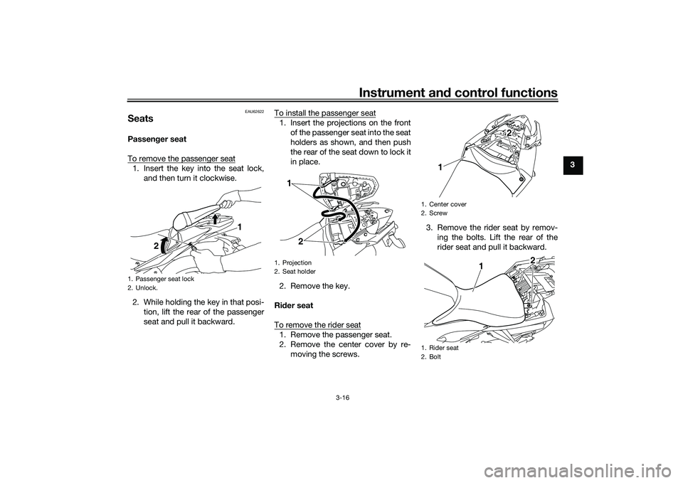
SeatsPassenger seat
To remove the passenger seat1. Insert the key into the seat lock,
and then turn it clockwise.
2. While holding the key in that posi-
tion, lift the rear of the passenger
seat and pull it backward.To install the passenger seat
1. Insert the projections on the front
of the passenger seat into the seat
holders as shown, and then push
the rear of the seat down to lock it
in place.
2. Remove the key.
Rider seat
To remove the rider seat1. Remove the passenger seat.
2. Remove the center cover by re-
moving the screws.3. Remove the rider seat by remov-
ing the bolts. Lift the rear of the
rider seat and pull it backward.
1. Passenger seat lock
2. Unlock.
1
2
1. Projection
2. Seat holder
1
2
1. Center cover
2. Screw
1. Rider seat
2. Bolt
12
12
UB04E0E0.book Page 16 Wednesday, September 2, 2015 3:51 PM