lock YAMAHA MT07 TRACER 2020 Owners Manual
[x] Cancel search | Manufacturer: YAMAHA, Model Year: 2020, Model line: MT07 TRACER, Model: YAMAHA MT07 TRACER 2020Pages: 98, PDF Size: 4.6 MB
Page 6 of 98

Table of contentsSafety information ............................ 1-1
Description ....................................... 2-1
Left view ......................................... 2-1
Right view ....................................... 2-2
Controls and instruments ............... 2-3
Instrument an d control functions ... 3-1
Immobilizer system......................... 3-1
Main switch/steering lock............... 3-2
Indicator lights and warning lights............................................ 3-3
Multi-function meter unit ................ 3-6
Handlebar switches ...................... 3-12
Clutch lever .................................. 3-13
Shift pedal .................................... 3-13
Brake lever.................................... 3-14
Brake pedal .................................. 3-14
ABS .............................................. 3-14
Fuel tank cap ................................ 3-15
Fuel ............................................... 3-16
Fuel tank breather hose and overflow hose ............................ 3-18
Catalytic converter ....................... 3-18
Seat .............................................. 3-19
Helmet holding cable.................... 3-19
Storage compartment .................. 3-20
Windshield ................................... 3-20
Adjusting the front fork ................. 3-21
Adjusting the shock absorber assembly ................................... 3-22 Luggage strap holders .................. 3-24
Auxiliary DC connector ................. 3-24
Sidestand ...................................... 3-25
Ignition circuit cut-off system ....... 3-25
For your safety – pre-operation
checks ............................................... 4-1
Operation an d important ri din g
points ................................................. 5-1
Engine break-in ............................... 5-1
Starting the engine .......................... 5-2
Shifting ............................................ 5-3
Tips for reducing fuel
consumption ................................ 5-4
Parking ............................................ 5-4
Perio dic maintenance an d
a d justment ........................................ 6-1
Tool kit ............................................ 6-2
Periodic maintenance charts .......... 6-3
Periodic maintenance chart for the emission control system .............. 6-3
General maintenance and lubrication chart ........................... 6-5
Checking the spark plugs ............... 6-9
Canister ......................................... 6-10
Engine oil and oil filter cartridge.... 6-10
Why Yamalube .............................. 6-13
Coolant.......................................... 6-13 Replacing the air filter element and
cleaning the check hose ........... 6-15
Checking the throttle grip free play ............................................ 6-15
Valve clearance............................. 6-16
Tires .............................................. 6-16
Cast wheels .................................. 6-18
Adjusting the clutch lever free
play ............................................ 6-19
Checking the brake lever free play ............................................ 6-19
Brake light switches ..................... 6-20
Checking the front and rear brake pads .......................................... 6-20
Checking the brake fluid level ...... 6-21
Changing the brake fluid .............. 6-22
Drive chain slack........................... 6-23
Cleaning and lubricating the drive chain.......................................... 6-24
Checking and lubricating the
cables ........................................ 6-25
Checking and lubricating the throttle grip and cable ............... 6-25
Checking and lubricating the brake and shift pedals............... 6-26
Checking and lubricating the
brake and clutch levers ............. 6-26
Checking and lubricating the sidestand................................... 6-27
Lubricating the rear suspension ... 6-27UB4TE0E0.book Page 1 Monday, December 9, 2019 3:53 PM
Page 13 of 98
Description
2-1
2
EAU10411
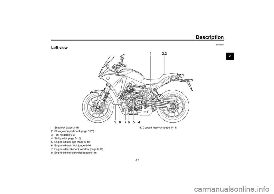
Left view
1
2,3
4
65
7
8
9
1. Seat lock (page 3-19)
2. Storage compartment (page 3-20)
3. Tool kit (page 6-2)
4. Shift pedal (page 3-13)
5. Engine oil filler cap (page 6-10)
6. Engine oil drain bolt (page 6-10)
7. Engine oil level check window (page 6-10)
8. Engine oil filter cartridge (page 6-10) 9. Coolant reservoir (page 6-13)
UB4TE0E0.book Page 1 Monday, December 9, 2019 3:53 PM
Page 15 of 98
Description
2-3
2
EAU10431
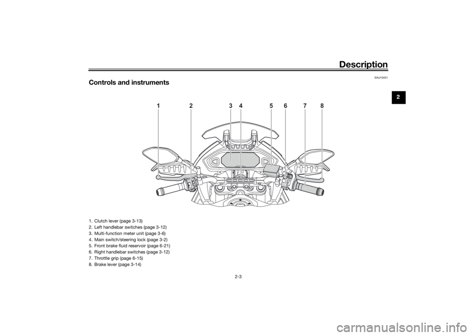
Controls and instruments
1
2
5
3
4
6
7
8
1. Clutch lever (page 3-13)
2. Left handlebar switches (page 3-12)
3. Multi-function meter unit (page 3-6)
4. Main switch/steering lock (page 3-2)
5. Front brake fluid reservoir (page 6-21)
6. Right handlebar switches (page 3-12)
7. Throttle grip (page 6-15)
8. Brake lever (page 3-14)
UB4TE0E0.book Page 3 Monday, December 9, 2019 3:53 PM
Page 17 of 98
Instrument and control functions
3-2
3
EAU10474
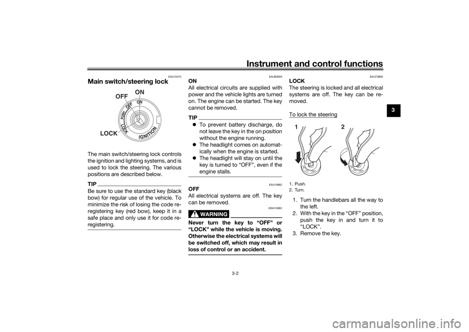
Main switch/steerin g lockThe main switch/steering lock controls
the ignition and lighting systems, and is
used to lock the steering. The various
positions are described below.TIPBe sure to use the standard key (black
bow) for regular use of the vehicle. To
minimize the risk of losing the code re-
registering key (red bow), keep it in a
safe place and only use it for code re-
registering.
EAU85050
ON
All electrical circuits are supplied with
power and the vehicle lights are turned
on. The engine can be started. The key
cannot be removed.TIP To prevent battery discharge, do
not leave the key in the on position
without the engine running.
The headlight comes on automat-
ically when the engine is started.
The headlight will stay on until the
key is turned to “OFF”, even if the
engine stalls.
EAU10662
OFF
All electrical systems are off. The key
can be removed.
WARNING
EWA10062
Never turn the key to “OFF” or
“LOCK” while the vehicle is movin g.
Otherwise the electrical systems will
b e switched off, which may result in
loss of control or an acci dent.
EAU73800
LOCK
The steering is locked and all electrical
systems are off. The key can be re-
moved.
To lock the steering1. Turn the handlebars all the way to
the left.
2. With the key in the “OFF” position, push the key in and turn it to
“LOCK”.
3. Remove the key.
ON
OFF
LOCK
1. Push.
2. Turn.12
UB4TE0E0.book Page 2 Monday, December 9, 2019 3:53 PM
Page 18 of 98
Instrument and control functions
3-3
3
TIPIf the steering will not lock, try turning
the handlebars back to the right slight-
ly.To unlock the steeringPush the key in and turn it to “OFF”.
EAU4939J
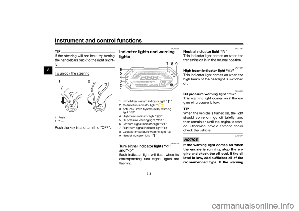
In dicator li ghts an d warnin g
li g hts
EAU11032
Turn si gnal in dicator li ghts “ ”
an d“”
Each indicator light will flash when its
corresponding turn signal lights are
flashing.
EAU11061
Neutral in dicator li ght “ ”
This indicator light comes on when the
transmission is in the neutral position.
EAU11081
Hi gh beam in dicator li ght “ ”
This indicator light comes on when the
high beam of the headlight is switched
on.
EAU59963
Oil pressure warnin g li ght “ ”
This warning light comes on if the en-
gine oil pressure is low.TIPWhen the vehicle is turned on, the light
should come on, go off briefly, and
then remain on until the engine is start-
ed. Otherwise, have a Yamaha dealer
check the vehicle.NOTICE
ECA21211
If the warnin g li ght comes on when
the en gine is runnin g, stop the en-
g ine an d check the oil level. If the oil
level is low, a dd sufficient oil of the
recommen ded type. If the warnin g
1. Push.
2. Turn.12
1. Immobilizer system indicator light “ ”
2. Malfunction indicator light “ ”
3. Anti-lock Brake System (ABS) warning
light “ ”
4. High beam indicator light “ ”
5. Oil pressure warning light “ ”
6. Left turn signal indicator light “ ”
7. Right turn signal indicator light “ ”
8. Coolant temperature warning light “ ”
9. Neutral indicator light “ ”1 2
3
4
5
6
789
ABS
UB4TE0E0.book Page 3 Monday, December 9, 2019 3:53 PM
Page 20 of 98
Instrument and control functions
3-5
3 closing of the throttle, racing,
burnouts, wheelies, extended
half-clutch use, etc.
EAU69895
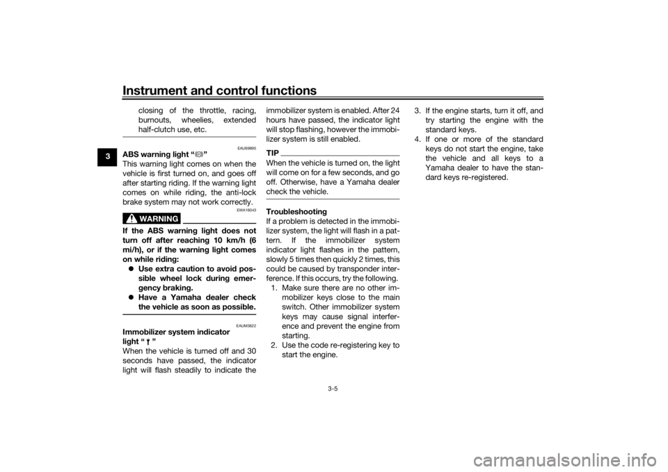
ABS warnin
g li ght “ ”
This warning light comes on when the
vehicle is first turned on, and goes off
after starting riding. If the warning light
comes on while riding, the anti-lock
brake system may not work correctly.
WARNING
EWA16043
If the ABS warnin g lig ht does not
turn off after reachin g 10 km/h (6
mi/h), or if the warnin g li ght comes
on while rid ing:
Use extra caution to avoi d pos-
si ble wheel lock d uring emer-
g ency brakin g.
Have a Yamaha dealer check
the vehicle as soon as possi ble.
EAUM3622
Immo bilizer system in dicator
li g ht “ ”
When the vehicle is turned off and 30
seconds have passed, the indicator
light will flash steadily to indicate the immobilizer system is enabled. After 24
hours have passed, the indicator light
will stop flashing, however the immobi-
lizer system is still enabled.
TIPWhen the vehicle is turned on, the light
will come on for a few seconds, and go
off. Otherwise, have a Yamaha dealer
check the vehicle.Trou
bleshootin g
If a problem is detected in the immobi-
lizer system, the light will flash in a pat-
tern. If the immobilizer system
indicator light flashes in the pattern,
slowly 5 times then quickly 2 times, this
could be caused by transponder inter-
ference. If this occurs, try the following. 1. Make sure there are no other im- mobilizer keys close to the main
switch. Other immobilizer system
keys may cause signal interfer-
ence and prevent the engine from
starting.
2. Use the code re-registering key to start the engine. 3. If the engine starts, turn it off, and
try starting the engine with the
standard keys.
4. If one or more of the standard keys do not start the engine, take
the vehicle and all keys to a
Yamaha dealer to have the stan-
dard keys re-registered.
ABS
UB4TE0E0.book Page 5 Monday, December 9, 2019 3:53 PM
Page 21 of 98
Instrument and control functions
3-6
3
EAUM4251
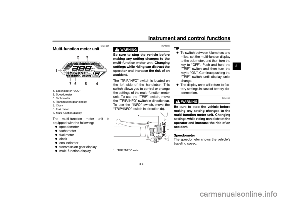
Multi-function meter unitThe multi-function meter unit is
equipped with the following:
speedometer
tachometer
fuel meter
clock
eco indicator
transmission gear display
multi-function display
WARNING
EWA12423
Be sure to stop the vehicle before
makin g any settin g chan ges to the
multi-function meter unit. Chan gin g
settin gs while ri din g can distract the
operator an d increase the risk of an
acci dent.The “TRIP/INFO” switch is located on
the left side of the handlebar. This
switch allows you to control or change
the settings of the multi-function meter
unit. To use the “TRIP” switch, move
the “TRIP/INFO” switch in direction (a).
To use the “INFO” switch, move the
“TRIP/INFO” switch in direction (b).
TIP To switch between kilometers and
miles, set the multi-funtion display
to the odometer, and then turn the
key to “OFF”. Push and hold the
“TRIP” switch and then turn the
key to “ON”. Continue pushing the
“TRIP” switch until display units
change.
The display units will return to fac-
tory settings in case of battery dis-
connection.
WARNING
EWA12423
Be sure to stop the vehicle before
makin g any settin g chan ges to the
multi-function meter unit. Chan gin g
settin gs while ri din g can d istract the
operator an d increase the risk of an
acci dent.Speed ometer
The speedometer shows the vehicle’s
traveling speed.
1. Eco indicator “ECO”
2. Speedometer
3. Tachometer
4. Transmission gear display
5. Clock
6. Fuel meter
7. Multi-function display
6
1 3
54
7
2
1. “TRIP/INFO” switch
1
UB4TE0E0.book Page 6 Monday, December 9, 2019 3:53 PM
Page 23 of 98
Instrument and control functions
3-8
3
Transmission
gear display
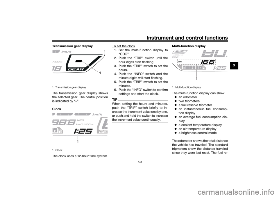
The transmission gear display shows
the selected gear. The neutral position
is indicated by “–”.
Clock
The clock uses a 12-hour time system. To set the clock
1. Set the multi-function display to
“ODO”
2. Push the “TRIP” switch until the hour digits start flashing.
3. Push the “TRIP” switch to set the hours.
4. Push the “INFO” switch and the minute digits will start flashing.
5. Push the “TRIP” switch to set the minutes.
6. Push the “INFO” switch to confirm settings and start the clock.TIPWhen setting the hours and minutes,
push the “TRIP” switch briefly to in-
crease the increment value one by one,
or push and hold the switch to increase
the increment value continuously.
Multi-function display
The multi-function display can show: an odometer
two tripmeters
a fuel reserve tripmeter
an instantaneous fuel consump-
tion display
an average fuel consumption dis-
play
a coolant temperature display
an air temperature display
a brightness control mode
The odometer shows the total distance
the vehicle has traveled. The standard
tripmeters show the distance traveled
since they were last reset. The fuel re-
1. Transmission gear display
1. Clock
1
1
1. Multi-function display
1
UB4TE0E0.book Page 8 Monday, December 9, 2019 3:53 PM
Page 24 of 98

Instrument and control functions
3-9
3 serve tripmeter shows the distance
traveled since the last segment of the
fuel meter began flashing.
TIP
The odometer will lock at 999999
and cannot be reset.
The tripmeter will reset to 0 and
continue counting after 9999.9 is
reached.Push the “TRIP” switch briefly to
switch the display in the following or-
der:
ODO → TRIP 1 → TRIP 2 → TRIP F →
km/L or L/100 km or MPG → AVE_ _._
km/L or AVE_ _._ L/100 km or AVE_ _._
MPG → _ _ °C → Air_ _ °C → ODOTIP Push the “INFO” switch briefly to
switch the display in the reverse
order.
The display changes to fuel re-
serve tripmeter “TRIP F” when the
last segment of the fuel meter
starts flashing.
To reset a tripmeter, select it by
pushing the “TRIP” switch or the
“INFO” switch, and while the dig-
its are flashing, push the “INFO”
switch until it is reset.
If you do not reset the fuel reserve
tripmeter manually, it will reset au-
tomatically and disappear from
the display after refueling and
traveling 5 km (3 mi).
Fuel reserve tripmeter
When the fuel level becomes low, the
last segment of the fuel meter will start
flashing. The fuel reserve tripmeter
“TRIP F” will automatically appear and
start counting the distance traveled
from that point. In this case, push the
“TRIP” switch to switch the display in
the following order:
TRIP F → km/L or L/100 km → AVE_
_._ km/L or AVE_ _._ L/100 km → _ _
°C → Air_ _ °C → ODO → TRIP 1 →
TRIP 2 → TRIP F For the UK:
TRIP F
→ MPG → AVE_ _._ MPG → _
_ °C → Air_ _ °C → ODO → TRIP 1 →
TRIP 2 → TRIP F
TIPPush the “INFO” switch to change
the display in the reverse order.
You can manually reset the fuel re-
serve tripmeter, or after refueling
and traveling 5 km (3 mi) it will re-
set automatically and disappear
from the display.Instantaneous fuel consumption
This function calculates the fuel con-
sumption under current riding condi-
tions.1. Instantaneous fuel consumption display
1
UB4TE0E0.book Page 9 Monday, December 9, 2019 3:53 PM
Page 28 of 98
Instrument and control functions
3-13
3 other drivers when your vehicle is
stopped where it might be a traffic haz-
ard.
With the main switch in the on position,
set the hazard lights switch to “ ” to
turn on the hazard lights. The main
switch can then be turned to the off po-
sition or lock position, however the
hazard lights will continue flash. To
turn off the hazard lighs, turn the main
switch to the on position and set this
switch to “OFF”.
NOTICE
ECA10062
Do not use the hazard
lights for an
exten ded len gth of time with the en-
g ine not runnin g, otherwise the bat-
tery may dischar ge.
EAUM3720
Trip/info switch “TRIP/INFO”
This switch is used to make setting and
display changes in the multi-function
meter unit. See page 3-6 for more in-
formation.
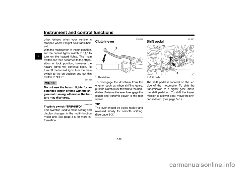
EAU12823
Clutch leverTo disengage the drivetrain from the
engine, such as when shifting gears,
pull the clutch lever toward to the han-
dlebar. Release the lever to engage the
clutch and transmit power to the rear
wheel.TIPThe lever should be pulled rapidly and
released slowly for smooth shifting.
(See page 5-3.)
EAU12876
Shift pe dalThe shift pedal is located on the left
side of the motorcycle. To shift the
transmission to a higher gear, move
the shift pedal up. To shift the trans-
mission to a lower gear, move the shift
pedal down. (See page 5-3.)
1. Clutch lever
1
1. Shift pedalZAUM1342
1
UB4TE0E0.book Page 13 Monday, December 9, 2019 3:53 PM