tow bar YAMAHA MT07 TRACER 2020 Owners Manual
[x] Cancel search | Manufacturer: YAMAHA, Model Year: 2020, Model line: MT07 TRACER, Model: YAMAHA MT07 TRACER 2020Pages: 98, PDF Size: 4.6 MB
Page 27 of 98

Instrument and control functions
3-12
3
EAU1234N
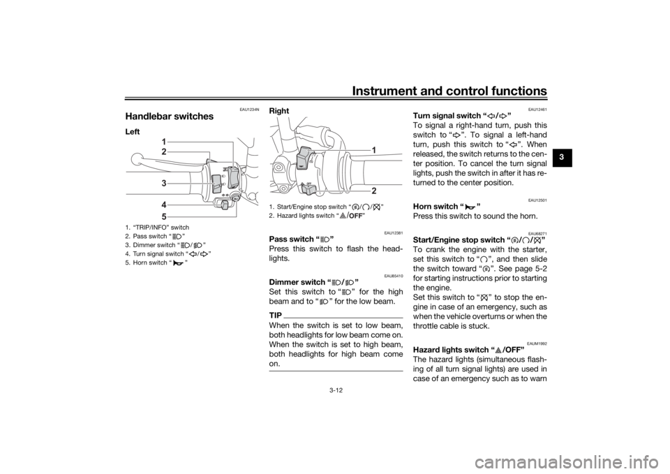
Han dle bar switchesLeft Ri
ght
EAU12381
Pass switch “ ”
Press this switch to flash the head-
lights.
EAU85410
Dimmer switch “ / ”
Set this switch to “ ” for the high
beam and to “ ” for the low beam.TIPWhen the switch is set to low beam,
both headlights for low beam come on.
When the switch is set to high beam,
both headlights for high beam come
on.
EAU12461
Turn si gnal switch “ / ”
To signal a right-hand turn, push this
switch to “ ”. To signal a left-hand
turn, push this switch to “ ”. When
released, the switch returns to the cen-
ter position. To cancel the turn signal
lights, push the switch in after it has re-
turned to the center position.
EAU12501
Horn switch “ ”
Press this switch to sound the horn.
EAU68271
Start/En gine stop switch “ / / ”
To crank the engine with the starter,
set this switch to “ ”, and then slide
the switch toward “ ”. See page 5-2
for starting instructions prior to starting
the engine.
Set this switch to “ ” to stop the en-
gine in case of an emergency, such as
when the vehicle overturns or when the
throttle cable is stuck.
EAUM1992
Hazar d lig hts switch “ /OFF”
The hazard lights (simultaneous flash-
ing of all turn signal lights) are used in
case of an emergency such as to warn
1. “TRIP/INFO” switch
2. Pass switch “ ”
3. Dimmer switch “ / ”
4. Turn signal switch “ / ”
5. Horn switch “ ”
34521
1. Start/Engine stop switch “ / / ”
2. Hazard lights switch “ ”
12
/
UB4TE0E0.book Page 12 Monday, December 9, 2019 3:53 PM
Page 28 of 98

Instrument and control functions
3-13
3 other drivers when your vehicle is
stopped where it might be a traffic haz-
ard.
With the main switch in the on position,
set the hazard lights switch to “ ” to
turn on the hazard lights. The main
switch can then be turned to the off po-
sition or lock position, however the
hazard lights will continue flash. To
turn off the hazard lighs, turn the main
switch to the on position and set this
switch to “OFF”.
NOTICE
ECA10062
Do not use the hazard
lights for an
exten ded len gth of time with the en-
g ine not runnin g, otherwise the bat-
tery may dischar ge.
EAUM3720
Trip/info switch “TRIP/INFO”
This switch is used to make setting and
display changes in the multi-function
meter unit. See page 3-6 for more in-
formation.
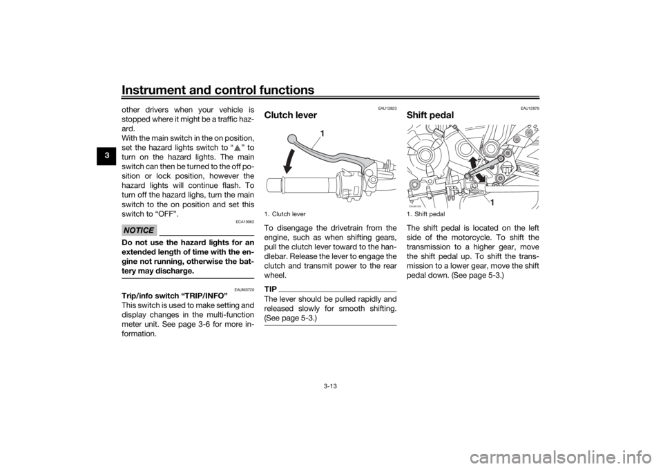
EAU12823
Clutch leverTo disengage the drivetrain from the
engine, such as when shifting gears,
pull the clutch lever toward to the han-
dlebar. Release the lever to engage the
clutch and transmit power to the rear
wheel.TIPThe lever should be pulled rapidly and
released slowly for smooth shifting.
(See page 5-3.)
EAU12876
Shift pe dalThe shift pedal is located on the left
side of the motorcycle. To shift the
transmission to a higher gear, move
the shift pedal up. To shift the trans-
mission to a lower gear, move the shift
pedal down. (See page 5-3.)
1. Clutch lever
1
1. Shift pedalZAUM1342
1
UB4TE0E0.book Page 13 Monday, December 9, 2019 3:53 PM
Page 29 of 98

Instrument and control functions
3-14
3
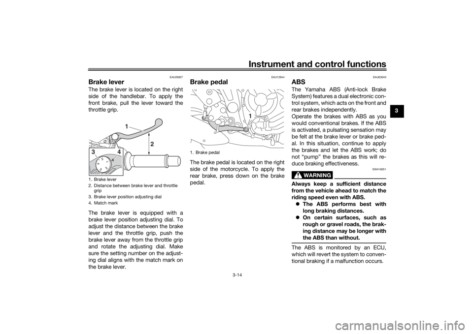
EAU26827
Brake leverThe brake lever is located on the right
side of the handlebar. To apply the
front brake, pull the lever toward the
throttle grip.
The brake lever is equipped with a
brake lever position adjusting dial. To
adjust the distance between the brake
lever and the throttle grip, push the
brake lever away from the throttle grip
and rotate the adjusting dial. Make
sure the setting number on the adjust-
ing dial aligns with the match mark on
the brake lever.
EAU12944
Brake ped alThe brake pedal is located on the right
side of the motorcycle. To apply the
rear brake, press down on the brake
pedal.
EAU63040
ABSThe Yamaha ABS (Anti-lock Brake
System) features a dual electronic con-
trol system, which acts on the front and
rear brakes independently.
Operate the brakes with ABS as you
would conventional brakes. If the ABS
is activated, a pulsating sensation may
be felt at the brake lever or brake ped-
al. In this situation, continue to apply
the brakes and let the ABS work; do
not “pump” the brakes as this will re-
duce braking effectiveness.
WARNING
EWA16051
Always keep a sufficient d istance
from the vehicle ahead to match the
ri din g speed even with ABS.
The ABS performs b est with
lon g b rakin g d istances.
On certain surfaces, such as
roug h or g ravel roa ds, the b rak-
in g d istance may be lon ger with
the ABS than without.The ABS is monitored by an ECU,
which will revert the system to conven-
tional braking if a malfunction occurs.
1. Brake lever
2. Distance between brake lever and throttle grip
3. Brake lever position adjusting dial
4. Match mark
1
2
43
1. Brake pedal
1
UB4TE0E0.book Page 14 Monday, December 9, 2019 3:53 PM