warning light YAMAHA MT07 TRACER 2020 Owners Manual
[x] Cancel search | Manufacturer: YAMAHA, Model Year: 2020, Model line: MT07 TRACER, Model: YAMAHA MT07 TRACER 2020Pages: 98, PDF Size: 4.6 MB
Page 6 of 98

Table of contentsSafety information ............................ 1-1
Description ....................................... 2-1
Left view ......................................... 2-1
Right view ....................................... 2-2
Controls and instruments ............... 2-3
Instrument an d control functions ... 3-1
Immobilizer system......................... 3-1
Main switch/steering lock............... 3-2
Indicator lights and warning lights............................................ 3-3
Multi-function meter unit ................ 3-6
Handlebar switches ...................... 3-12
Clutch lever .................................. 3-13
Shift pedal .................................... 3-13
Brake lever.................................... 3-14
Brake pedal .................................. 3-14
ABS .............................................. 3-14
Fuel tank cap ................................ 3-15
Fuel ............................................... 3-16
Fuel tank breather hose and overflow hose ............................ 3-18
Catalytic converter ....................... 3-18
Seat .............................................. 3-19
Helmet holding cable.................... 3-19
Storage compartment .................. 3-20
Windshield ................................... 3-20
Adjusting the front fork ................. 3-21
Adjusting the shock absorber assembly ................................... 3-22 Luggage strap holders .................. 3-24
Auxiliary DC connector ................. 3-24
Sidestand ...................................... 3-25
Ignition circuit cut-off system ....... 3-25
For your safety – pre-operation
checks ............................................... 4-1
Operation an d important ri din g
points ................................................. 5-1
Engine break-in ............................... 5-1
Starting the engine .......................... 5-2
Shifting ............................................ 5-3
Tips for reducing fuel
consumption ................................ 5-4
Parking ............................................ 5-4
Perio dic maintenance an d
a d justment ........................................ 6-1
Tool kit ............................................ 6-2
Periodic maintenance charts .......... 6-3
Periodic maintenance chart for the emission control system .............. 6-3
General maintenance and lubrication chart ........................... 6-5
Checking the spark plugs ............... 6-9
Canister ......................................... 6-10
Engine oil and oil filter cartridge.... 6-10
Why Yamalube .............................. 6-13
Coolant.......................................... 6-13 Replacing the air filter element and
cleaning the check hose ........... 6-15
Checking the throttle grip free play ............................................ 6-15
Valve clearance............................. 6-16
Tires .............................................. 6-16
Cast wheels .................................. 6-18
Adjusting the clutch lever free
play ............................................ 6-19
Checking the brake lever free play ............................................ 6-19
Brake light switches ..................... 6-20
Checking the front and rear brake pads .......................................... 6-20
Checking the brake fluid level ...... 6-21
Changing the brake fluid .............. 6-22
Drive chain slack........................... 6-23
Cleaning and lubricating the drive chain.......................................... 6-24
Checking and lubricating the
cables ........................................ 6-25
Checking and lubricating the throttle grip and cable ............... 6-25
Checking and lubricating the brake and shift pedals............... 6-26
Checking and lubricating the
brake and clutch levers ............. 6-26
Checking and lubricating the sidestand................................... 6-27
Lubricating the rear suspension ... 6-27UB4TE0E0.book Page 1 Monday, December 9, 2019 3:53 PM
Page 17 of 98
Instrument and control functions
3-2
3
EAU10474
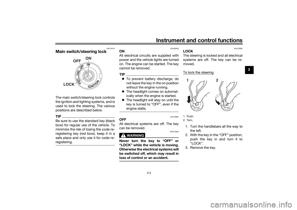
Main switch/steerin g lockThe main switch/steering lock controls
the ignition and lighting systems, and is
used to lock the steering. The various
positions are described below.TIPBe sure to use the standard key (black
bow) for regular use of the vehicle. To
minimize the risk of losing the code re-
registering key (red bow), keep it in a
safe place and only use it for code re-
registering.
EAU85050
ON
All electrical circuits are supplied with
power and the vehicle lights are turned
on. The engine can be started. The key
cannot be removed.TIP To prevent battery discharge, do
not leave the key in the on position
without the engine running.
The headlight comes on automat-
ically when the engine is started.
The headlight will stay on until the
key is turned to “OFF”, even if the
engine stalls.
EAU10662
OFF
All electrical systems are off. The key
can be removed.
WARNING
EWA10062
Never turn the key to “OFF” or
“LOCK” while the vehicle is movin g.
Otherwise the electrical systems will
b e switched off, which may result in
loss of control or an acci dent.
EAU73800
LOCK
The steering is locked and all electrical
systems are off. The key can be re-
moved.
To lock the steering1. Turn the handlebars all the way to
the left.
2. With the key in the “OFF” position, push the key in and turn it to
“LOCK”.
3. Remove the key.
ON
OFF
LOCK
1. Push.
2. Turn.12
UB4TE0E0.book Page 2 Monday, December 9, 2019 3:53 PM
Page 18 of 98
Instrument and control functions
3-3
3
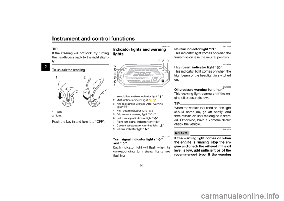
TIPIf the steering will not lock, try turning
the handlebars back to the right slight-
ly.To unlock the steeringPush the key in and turn it to “OFF”.
EAU4939J
In dicator li ghts an d warnin g
li g hts
EAU11032
Turn si gnal in dicator li ghts “ ”
an d“”
Each indicator light will flash when its
corresponding turn signal lights are
flashing.
EAU11061
Neutral in dicator li ght “ ”
This indicator light comes on when the
transmission is in the neutral position.
EAU11081
Hi gh beam in dicator li ght “ ”
This indicator light comes on when the
high beam of the headlight is switched
on.
EAU59963
Oil pressure warnin g li ght “ ”
This warning light comes on if the en-
gine oil pressure is low.TIPWhen the vehicle is turned on, the light
should come on, go off briefly, and
then remain on until the engine is start-
ed. Otherwise, have a Yamaha dealer
check the vehicle.NOTICE
ECA21211
If the warnin g li ght comes on when
the en gine is runnin g, stop the en-
g ine an d check the oil level. If the oil
level is low, a dd sufficient oil of the
recommen ded type. If the warnin g
1. Push.
2. Turn.12
1. Immobilizer system indicator light “ ”
2. Malfunction indicator light “ ”
3. Anti-lock Brake System (ABS) warning
light “ ”
4. High beam indicator light “ ”
5. Oil pressure warning light “ ”
6. Left turn signal indicator light “ ”
7. Right turn signal indicator light “ ”
8. Coolant temperature warning light “ ”
9. Neutral indicator light “ ”1 2
3
4
5
6
789
ABS
UB4TE0E0.book Page 3 Monday, December 9, 2019 3:53 PM
Page 19 of 98
Instrument and control functions
3-4
3
lig
ht remains on after addin g oil,
stop the en gine an d have a Yamaha
d ealer check the vehicle.
EAU11449
Coolant temperature warnin g
lig ht “ ”
This warning light comes on when the
engine is overheating. If this occurs,
stop the engine immediately and allow
the engine to cool. (See page 6-36.)
For vehicles with a radiator fan, the ra-
diator fan(s) automatically switch on or
off according to the coolant tempera-
ture.TIPWhen the vehicle is turned on, the light
will come on for a few seconds, and
then go off. If the light does not come
on, or if the light remains on, have a
Yamaha dealer check the vehicle. NOTICE
ECA10022
Do not continue to operate the en-
g ine if it is overheatin g.
EAU88330
Malfunction in dicator li ght
(MIL) “ ”
This light comes on or flashes if a prob-
lem is detected in the engine or other
vehicle control system. If this occurs,
have a Yamaha dealer check the on-
board diagnostic system. The electri-
cal circuit of the warning light can be
checked by vehicle power on. The light
should come on for a few seconds,
and then go off. If the light does not
come on initially when the vehicle pow-
er on, or if the light remains on, have a
Yamaha dealer check the vehicle.NOTICE
ECA26820
If the MIL starts flashin g, re duce en-
g ine spee d to prevent exhaust sys-
tem damag e.TIPThe engine is sensitively controlled for
the on-board diagnostic system to de-
tect deterioration and malfunction of
the emission control system. Due to
this specification, the MIL may come
on or flash for vehicle modifications,
lack of maintenance, or excessive or improper use of the motorcycle. To
prevent this, observe these precau-
tions.
Do not attempt to modify the soft-
ware of the engine control unit.
Do not add any electrical acces-
sories that interfere with engine
control.
Do not use aftermarket accesso-
ries or parts such as suspension,
spark plugs, injectors, exhaust
system, etc.
Do not change drivetrain specifi-
cations (chain, sprockets, wheels,
tires, etc.).
Do not remove or alter the O2 sen-
sor, air induction system, or ex-
haust parts (catalysts or EXUP,
etc.).
Maintain proper drive chain.
Maintain correct tire pressure.
Maintain proper brake pedal
height to prevent rear brake from
dragging.
Do not operate the vehicle in an
extreme manner. For example, re-
peated or excessive opening and
UB4TE0E0.book Page 4 Monday, December 9, 2019 3:53 PM
Page 20 of 98
Instrument and control functions
3-5
3 closing of the throttle, racing,
burnouts, wheelies, extended
half-clutch use, etc.
EAU69895
ABS warnin
g li ght “ ”
This warning light comes on when the
vehicle is first turned on, and goes off
after starting riding. If the warning light
comes on while riding, the anti-lock
brake system may not work correctly.
WARNING
EWA16043
If the ABS warnin g lig ht does not
turn off after reachin g 10 km/h (6
mi/h), or if the warnin g li ght comes
on while rid ing:
Use extra caution to avoi d pos-
si ble wheel lock d uring emer-
g ency brakin g.
Have a Yamaha dealer check
the vehicle as soon as possi ble.
EAUM3622
Immo bilizer system in dicator
li g ht “ ”
When the vehicle is turned off and 30
seconds have passed, the indicator
light will flash steadily to indicate the immobilizer system is enabled. After 24
hours have passed, the indicator light
will stop flashing, however the immobi-
lizer system is still enabled.
TIPWhen the vehicle is turned on, the light
will come on for a few seconds, and go
off. Otherwise, have a Yamaha dealer
check the vehicle.Trou
bleshootin g
If a problem is detected in the immobi-
lizer system, the light will flash in a pat-
tern. If the immobilizer system
indicator light flashes in the pattern,
slowly 5 times then quickly 2 times, this
could be caused by transponder inter-
ference. If this occurs, try the following. 1. Make sure there are no other im- mobilizer keys close to the main
switch. Other immobilizer system
keys may cause signal interfer-
ence and prevent the engine from
starting.
2. Use the code re-registering key to start the engine. 3. If the engine starts, turn it off, and
try starting the engine with the
standard keys.
4. If one or more of the standard keys do not start the engine, take
the vehicle and all keys to a
Yamaha dealer to have the stan-
dard keys re-registered.
ABS
UB4TE0E0.book Page 5 Monday, December 9, 2019 3:53 PM
Page 31 of 98
Instrument and control functions
3-16
3
TIPThe fuel tank cap cannot be closed un-
less the key is in the lock. In addition,
the key cannot be removed if the cap is
not properly closed and locked.
WARNING
EWA11092
Make sure that the fuel tank cap is
properly closed after filling fuel.
Leakin g fuel is a fire hazar d.
EAU13222
FuelMake sure there is sufficient gasoline in
the tank.
WARNING
EWA10882
Gasoline an d gasoline vapors are
extremely flammab le. To avoid fires
an d explosions an d to re duce the
risk of injury when refueling , follow
these instructions.1. Before refueling, turn off the en- gine and be sure that no one is sit-
ting on the vehicle. Never refuel
while smoking, or while in the vi-
cinity of sparks, open flames, or
other sources of ignition such as
the pilot lights of water heaters
and clothes dryers.
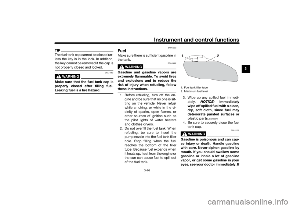
2. Do not overfill the fuel tank. When refueling, be sure to insert the
pump nozzle into the fuel tank filler
hole. Stop filling when the fuel
reaches the bottom of the filler
tube. Because fuel expands when
it heats up, heat from the engine or
the sun can cause fuel to spill out
of the fuel tank. 3. Wipe up any spilled fuel immedi-
ately. NOTICE: Immediately
wipe off spille d fuel with a clean,
d ry, soft cloth, since fuel may
d eteriorate painte d surfaces or
plastic parts.
[ECA10072]
4. Be sure to securely close the fuel tank cap.
WARNING
EWA15152
Gasoline is poisonous an d can cau-
se injury or death. Han dle gasoline
with care. Never siphon gasoline by
mouth. If you shoul d swallow some
g asoline or inhale a lot of g asoline
vapor, or g et some gasoline in your
eyes, see your d octor immediately. If1. Fuel tank filler tube
2. Maximum fuel level
2
1
UB4TE0E0.book Page 16 Monday, December 9, 2019 3:53 PM
Page 46 of 98
Operation and important rid ing points
5-2
5
EAU86620
Startin g the eng ineThe ignition circuit cut-off system will
enable starting when:
the transmission is in the neutral
position or
the transmission is in gear, the
sidestand is up, and the clutch le-
ver is pulled.
To start the engine1. Turn the main switch on and set the engine stop switch to the run
position.
2. Confirm the indicator and warning light(s) come on for a few sec-
onds, and the go off. (See page
3-3.)TIPDo not start the engine if the en-
gine trouble warning light remains
on.
The oil pressure warning light
should come on and stay on until
the engine is started.
The ABS warning light should
come on and stay on until the ve-
hicle reaches a speed of 10 km/h
(6 mi/h).
NOTICE
ECA24110
If a warnin g or in dicator li ght does
not work as d escribed a bove, have a
Yamaha dealer check the vehicle.3. Shift the transmission into the
neutral position.
4. Start the engine by pushing the start switch.
5. Release the start switch when the engine starts, or after 5 seconds.
Wait 10 seconds before pressing
the switch again to allow battery
voltage to restore.NOTICE
ECA11043
For maximum en gine life, never ac-
celerate har d when the en gine is
col d!
EAUM3632
TIPThis model is equipped with:
a lean angle sensor. This sensor
stops the engine in case of a vehi-
cle turnover. If this happens, the
engine trouble warning light will
come on, but this is not a malfunc-
tion. Turn the vehicle power off
and then back on again to cancel
the warning light. Failing to do so
will prevent the engine from start-
ing even though the engine will
crank when pushing the start
switch.
an engine auto-stop system. The
engine stops automatically if left
idling for 20 minutes. If the engine
stops, simply push the start
switch to restart the engine.
UB4TE0E0.book Page 2 Monday, December 9, 2019 3:53 PM
Page 48 of 98
Operation and important rid ing points
5-4
5 The neutral indicator light should
come on and then the clutch lever
can be released.
WARNING
EWA17380
Improper brakin g can cause
loss of control or traction. Al-
ways use b oth brakes an d apply
them smoothly.
Make sure that the motorcycle
and the en gine have sufficiently
slowe d b efore shiftin g to a low-
er gear. En gag in g a lower gear
when the vehicle or en gine
speed is too hi gh coul d make
the rear wheel lose traction or
the en gine to over-rev. This
coul d cause loss of control, an
acci dent an d injury. It coul d also
cause en gine or drive train dam-
a g e.
EAU16811
Tips for re ducin g fuel con-
sumptionFuel consumption depends largely on
your riding style. Consider the follow-
ing tips to reduce fuel consumption:
Shift up swiftly, and avoid high en-
gine speeds during acceleration.
Do not rev the engine while shift-
ing down, and avoid high engine
speeds with no load on the en-
gine.
Turn the engine off instead of let-
ting it idle for an extended length
of time (e.g., in traffic jams, at traf-
fic lights or at railroad crossings).
EAU17214
Parkin gWhen parking, stop the engine, and
then remove the key from the main
switch.
WARNING
EWA10312
Since the en gine an d exhaust
system can become very hot,
park in a place where pe destri-
ans or chil dren are not likely to
touch them an d b e burne d.
Do not park on a slope or on soft
groun d, otherwise the vehicle
may overturn, increasin g the
risk of a fuel leak an d fire.
Do not park near grass or other
flammab le materials which
mi ght catch fire.
UB4TE0E0.book Page 4 Monday, December 9, 2019 3:53 PM
Page 60 of 98

Periodic maintenance an d a djustment
6-12
6
8. Install the engine oil drain bolt andits new gasket, and then tighten
the bolt to the specified torque.
9. Refill with the specified amount of the recommended engine oil.
TIPBe sure to wipe off spilled oil on any
parts after the engine and exhaust sys-
tem have cooled down.NOTICE
ECA11621
In or der to prevent clutch slip-
pa ge (since the en gine oil also
lu bricates the clutch), do not
mix any chemical additives. Do
not use oils with a diesel speci-
fication of “CD” or oils of a hi gh-
er quality than specifie d. In
a ddition, do not use oils la beled
“ENERGY CONSERVING II” or
hi gher.
Make sure that no forei gn mate-
rial enters the crankcase.
10. Check the O-ring for damage, and replace it if necessary.
11. Install and tighten the engine oil filler cap.
12. Start the engine, and then let it idle for several minutes while checking
it for oil leakage. If oil is leaking,
immediately turn the engine off
and check for the cause.TIPAfter the engine is started, the engine
oil pressure warning light should go off.
1. Torque wrenchTightenin g torque:
Oil filter cartridge: 17 N·m (1.7 kgf·m, 13 lb·ft)
Ti ghtenin g torque:
Engine oil drain bolt:
43 N·m (4.3 kgf·m, 32 lb·ft)1
Recommen ded en gine oil:
See page 8-1.
Oil quantity: Without oil filter cartridge replace-
ment:2.30 L (2.43 US qt, 2.02 Imp.qt)
With oil filter cartridge replacement:
2.60 L (2.75 US qt, 2.29 Imp.qt)
1. Engine oil filler cap
2. O-ring
21
UB4TE0E0.book Page 12 Monday, December 9, 2019 3:53 PM
Page 79 of 98
Periodic maintenance and adjustment
6-31
6
EAU47175
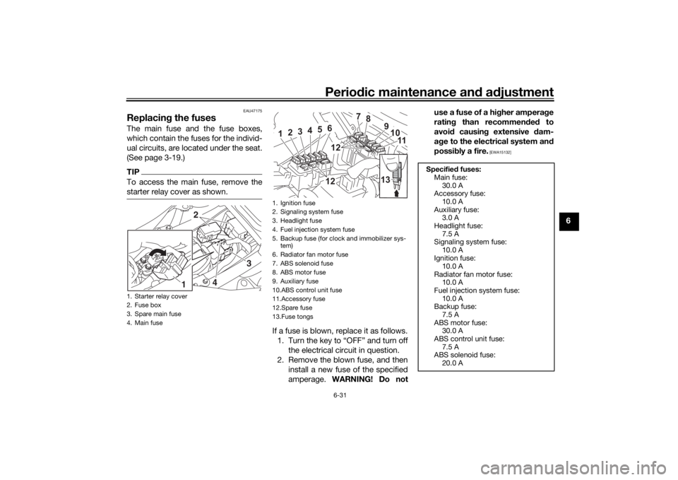
Replacing the fusesThe main fuse and the fuse boxes,
which contain the fuses for the individ-
ual circuits, are located under the seat.
(See page 3-19.)TIPTo access the main fuse, remove the
starter relay cover as shown.
If a fuse is blown, replace it as follows.1. Turn the key to “OFF” and turn off the electrical circuit in question.
2. Remove the blown fuse, and then install a new fuse of the specified
amperage. WARNING! Do not use a fuse of a higher amperage
rating than recommended to
avoid causing extensive dam-
age to the electrical system and
possibly a fire.
[EWA15132]
1. Starter relay cover
2. Fuse box
3. Spare main fuse
4. Main fuse
2
3
4
1
1. Ignition fuse
2. Signaling system fuse
3. Headlight fuse
4. Fuel injection system fuse
5. Backup fuse (for clock and immobilizer sys-
tem)
6. Radiator fan motor fuse
7. ABS solenoid fuse
8. ABS motor fuse
9. Auxiliary fuse
10.ABS control unit fuse
11.Accessory fuse
12.Spare fuse
13.Fuse tongs
7
8
10 11
1
2
3
4
5
61212 9
13
Specified fuses:
Main fuse: 30.0 A
Accessory fuse:
10.0 A
Auxiliary fuse: 3.0 A
Headlight fuse: 7.5 A
Signaling system fuse:
10.0 A
Ignition fuse: 10.0 A
Radiator fan motor fuse: 10.0 A
Fuel injection system fuse:
10.0 A
Backup fuse: 7.5 A
ABS motor fuse: 30.0 A
ABS control unit fuse:
7.5 A
ABS solenoid fuse: 20.0 A
UB4TE1E0.book Page 31 Monday, December 23, 2019 3:05 PM