sensor YAMAHA MT09 TRACER 2017 Owners Manual
[x] Cancel search | Manufacturer: YAMAHA, Model Year: 2017, Model line: MT09 TRACER, Model: YAMAHA MT09 TRACER 2017Pages: 114, PDF Size: 5.27 MB
Page 37 of 114

Instrument and control functions
3-22
1
234
5
6
7
8
9
10
11
12
TIP
The ABS performs a self-diagno-
sis test each time the vehicle first
starts off after the key is turned to
“ON” and the vehicle has traveled
at a speed of 10 km/h (6 mi/h) or
higher. During this test, a “clicking”
noise can be heard from the hy-
draulic control unit, and if the brake
lever or brake pedal is even slight-
ly applied, a vibration can be felt at
the lever and pedal, but these do
not indicate a malfunction.
This ABS has a test mode which
allows the owner to experience the
pulsation at the brake lever or
brake pedal when the ABS is oper-
ating. However, special tools are
required, so please consult yourYamaha dealer.
NOTICE
ECA20100
Be careful not to damage the wheel
sensor or wheel sensor rotor; other-
wise, improper performance of theABS will result.
EAU76313
Traction control systemThe traction control system (TCS)
helps maintain traction when accelerat-
ing on slippery surfaces, such as un-
paved or wet roads. If sensors detect
that the rear wheel is starting to slip (un-
controlled spinning), the traction control
system assists by regulating engine
power as needed until traction is re-
stored.
WARNING
EWA15432
The traction control system is not a
substitute for riding appropriately
for the conditions. Traction control
cannot prevent loss of traction due
to excessive speed when entering
turns, when accelerating hard at a
sharp lean angle, or while braking,
and cannot prevent front wheel slip-
ping. As with any motorcycle, ap-
proach surfaces that may be
slippery with caution and avoid es-pecially slippery surfaces.
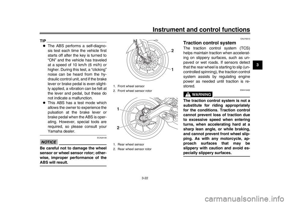
1. Front wheel sensor
2. Front wheel sensor rotor
1. Rear wheel sensor
2. Rear wheel sensor rotor
21
12
2PP-9-E3.book 22 ページ 2016年9月13日 火曜日 午前9時7分
Page 58 of 114

5-1
1
2
3
45
6
7
8
9
10
11
12
Operation and important riding points
EAU15952
Read the Owner’s Manual carefully to
become familiar with all controls. If
there is a control or function you do not
understand, ask your Yamaha dealer.
WARNING
EWA10272
Failure to familiarize yourself with
the controls can lead to loss of con-
trol, which could cause an accidentor injury.
EAUM3631
TIPThis model is equipped with:
a lean angle sensor to stop the en-
gine in case of a turnover. In this
case, the engine trouble warning
light will come on, but this is not a
malfunction. Turn the key to “OFF”
and then to “ON” to turn off the
warning light. Failing to do so will
prevent the engine from starting
even though the engine will crank
when pushing the start switch.
an engine auto-stop system. The
engine stops automatically if left
idling for 20 minutes. If the engine
stops, simply push the start switchto restart the engine.
EAU73430
Starting the engineIn order for the ignition circuit cut-off
system to enable starting, one of the
following conditions must be met:
The transmission is in the neutral
position.
The transmission is in gear with
the clutch lever pulled and the sid-
estand up.
See page 3-37 for more informa-
tion.
1. Turn the key to “ON” and make sure that the start/engine stop
switch is set to “ ”.
The following warning lights and
indicator light should come on for a
few seconds, then go off.
Oil level warning light
Coolant temperature warning
light
Engine trouble warning light
Immobilizer system indicator
light
NOTICE
ECA17671
If the above warning lights or indica-
tor light do not come on initially
when the key is turned to “ON”, or if
2PP-9-E3.book 1 ページ 2016年9月13日 火曜日 午前9時7分
Page 110 of 114

Consumer information
9-2
1
2
3
4
5
6
7
89
10
11
12
EAU26461
Model label
The model label is affixed to the loca-
tion shown. Record the information on
this label in the space provided. This in-
formation will be needed when ordering
spare parts from a Yamaha dealer.
EAU69910
Diagnostic connectorThe diagnostic connector is located as
shown.
EAU74701
Vehicle data recordingThis model’s ECU stores certain vehi-
cle data to assist in the diagnosis of
malfunctions and for research and de-
velopment purposes. This data will be
uploaded only when a special Yamaha
diagnostic tool is attached to the vehi-
cle, such as when maintenance checks
or service procedures are performed.
Although the sensors and recorded
data will vary by model, the main data
points are:
Vehicle status and engine perfor-
mance data
Fuel-injection and emission-relat-
ed data
Yamaha will not disclose this data to a
third party except:
With the consent of the vehicle
owner
Where obligated by law
For use by Yamaha in litigation
For general Yamaha-conducted
research purposes when the data
is not related to an individual vehi-
cle nor owner
1. Model label
1
1. Diagnostic connector
1
2PP-9-E3.book 2 ページ 2016年9月13日 火曜日 午前9時7分