stop start YAMAHA MT09 TRACER 2017 Owners Manual
[x] Cancel search | Manufacturer: YAMAHA, Model Year: 2017, Model line: MT09 TRACER, Model: YAMAHA MT09 TRACER 2017Pages: 114, PDF Size: 5.27 MB
Page 23 of 114
Instrument and control functions
3-8
1
234
5
6
7
8
9
10
11
12
High-rpm zone: 11250 r/min and
above
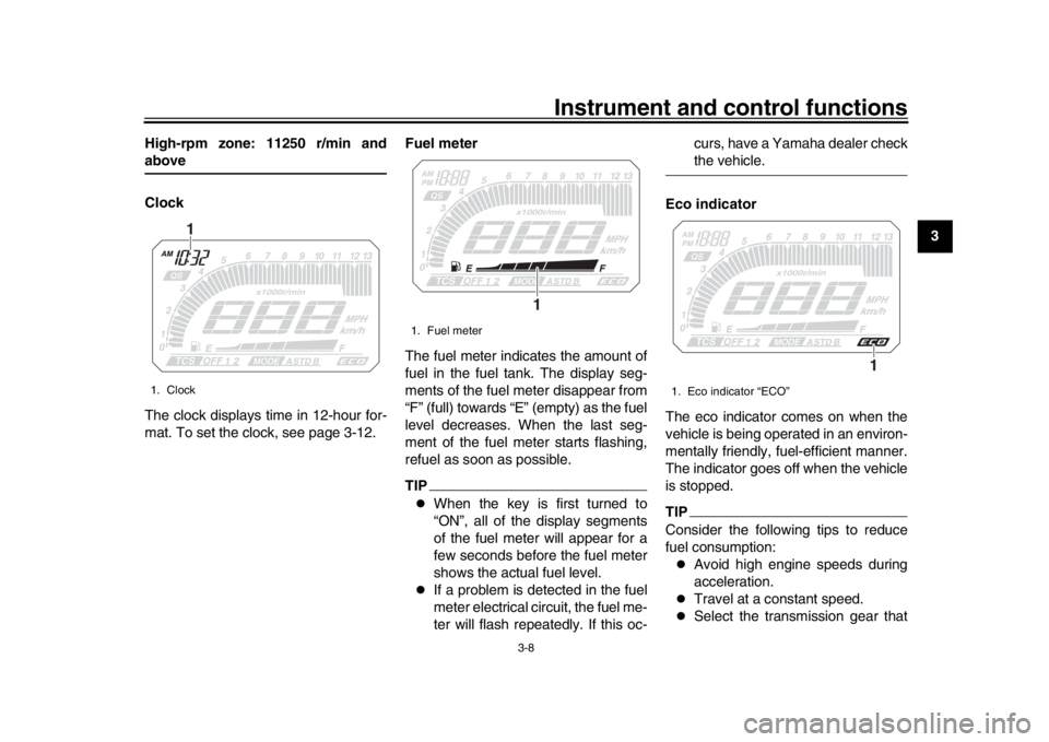
Clock
The clock displays time in 12-hour for-
mat. To set the clock, see page 3-12.
Fuel meter
The fuel meter indicates the amount of
fuel in the fuel tank. The display seg-
ments of the fuel meter disappear from
“F” (full) towards “E” (empty) as the fuel
level decreases. When the last seg-
ment of the fuel meter starts flashing,
refuel as soon as possible.
TIP
When the key is first turned to
“ON”, all of the display segments
of the fuel meter will appear for a
few seconds before the fuel meter
shows the actual fuel level.
If a problem is detected in the fuel
meter electrical circuit, the fuel me-
ter will flash repeatedly. If this oc-curs, have a Yamaha dealer check
the vehicle.
Eco indicator
The eco indicator comes on when the
vehicle is being operated in an environ-
mentally friendly, fuel-efficient manner.
The indicator goes off when the vehicle
is stopped.
TIPConsider the following tips to reduce
fuel consumption:
Avoid high engine speeds during
acceleration.
Travel at a constant speed.
Select the transmission gear that
1. Clock
1
1. Fuel meter
1
1. Eco indicator “ECO”
1
2PP-9-E3.book 8 ページ 2016年9月13日 火曜日 午前9時7分
Page 33 of 114
Instrument and control functions
3-18
1
234
5
6
7
8
9
10
11
12
This mode allows the rider to enjoy
smooth and sporty drivability from the
low-speed range to the high-speed
range.
Mode “A”
Mode “A” offers a sportier engine re-
sponse in the low- to mid-speed range
compared to mode “STD”.
Mode “B”
Mode “B” offers response that is some-
what less sharp compared to mode
“STD” for riding situations that require
especially sensitive throttle operation.
EAU1234M
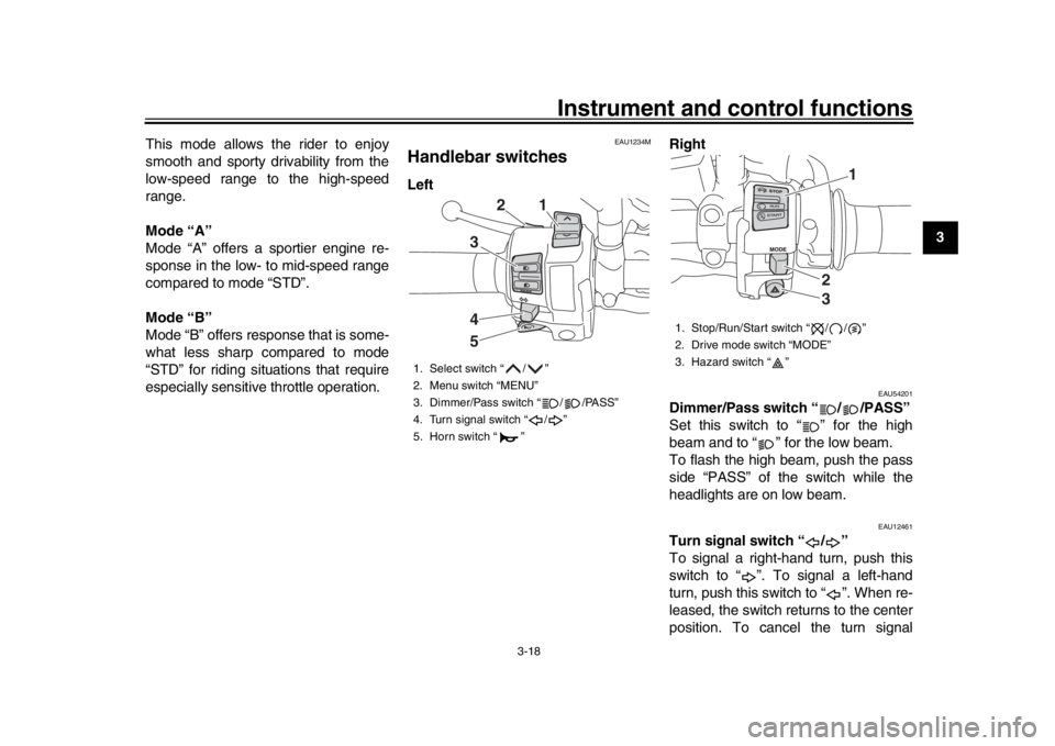
Handlebar switchesLeft
Right
EAU54201
Dimmer/Pass switch “ / /PASS”
Set this switch to “ ” for the high
beam and to “ ” for the low beam.
To flash the high beam, push the pass
side “PASS” of the switch while the
headlights are on low beam.
EAU12461
Turn signal switch “ / ”
To signal a right-hand turn, push this
switch to “ ”. To signal a left-hand
turn, push this switch to “ ”. When re-
leased, the switch returns to the center
position. To cancel the turn signal
1. Select switch “ / ”
2. Menu switch “MENU”
3. Dimmer/Pass switch “ / /PASS”
4. Turn signal switch “ / ”
5. Horn switch “ ”
2
1
345
1. Stop/Run/Start switch “ / / ”
2. Drive mode switch “MODE”
3. Hazard switch “ ”
1
23
2PP-9-E3.book 18 ページ 2016年9月13日 火曜日 午前9時7分
Page 34 of 114
Instrument and control functions
3-19
1
23
4
5
6
7
8
9
10
11
12 lights, push the switch in after it has re-
turned to the center position.
EAU12501
Horn switch “ ”
Press this switch to sound the horn.
EAU54212
Stop/Run/Start switch “ / / ”
To crank the engine with the starter, set
this switch to “ ”, and then push the
switch down towards “ ”. See page
5-1 for starting instructions prior to
starting the engine.
Set this switch to “ ” to stop the engine
in case of an emergency, such as when
the vehicle overturns or when the throt-
tle cable is stuck.
EAU12735
Hazard switch “ ”
With the key in the “ON” or “ ” posi-
tion, use this switch to turn on the haz-
ard lights (simultaneous flashing of all
turn signal lights).
The hazard lights are used in case of
an emergency or to warn other drivers
when your vehicle is stopped where it
might be a traffic hazard.
NOTICE
ECA10062
Do not use the hazard lights for an
extended length of time with the en-
gine not running, otherwise the bat-tery may discharge.
EAU59011
Menu switch “MENU”
This switch is used to perform selec-
tions in the setting mode display of the
multi-function meter unit.
See Multi-function meter unit on page
3-6 for detailed information.
EAU59001
Select switch “ / ”
This switch is used to perform selec-
tions in the information display and set-
ting mode display of the multi-function
meter unit.
See Multi-function meter unit on page
3-6 for detailed information.
EAU77020
Drive mode switch “MODE”
WARNING
EWA15341
Do not change the D-mode while the
vehicle is moving.
Using this switch changes the drive
mode to “STD”, “A”, or “B” in the follow-
ing order:
STD
A B STD
The throttle grip must be completely
closed in order to change the drive
mode. (See page 3-17 for an explana-
tion of each drive mode.)TIP
The current drive mode is saved
when the key is turned to “OFF”.
The selected mode is shown on
the drive mode display. (See page3-9.)
2PP-9-E3.book 19 ページ 2016年9月13日 火曜日 午前9時7分
Page 53 of 114

Instrument and control functions
3-38
1
234
5
6
7
8
9
10
11
12
With the engine turned off:
1. Move the sidestand down.
2. Make sure that the start/engine stop switch is set to “ ”.
3. Turn the key on.
4. Shift the transmission into the neutral position.
5. Push the “ ” side of the start/engine stop switch.
Does the engine start?
With the engine still running:
6. Move the sidestand up.
7. Keep the clutch lever pulled.
8. Shift the transmission into gear.
9. Move the sidestand down.
Does the engine stall?
After the engine has stalled:
10. Move the sidestand up.
11. Keep the clutch lever pulled.
12. Push the “ ” side of the start/engine stop switch.
Does the engine start?
The system is OK. The motorcycle can be ridden.
YES NO YES NO YES NO
The neutral switch may not be working correctly.
The motorcycle should not be ridden until
checked by a Yamaha dealer.
The clutch switch may not be working correctly.
The motorcycle should not be ridden until
checked by a Yamaha dealer.The sidestand switch may not be working correctly.
The motorcycle should not be ridden until
checked by a Yamaha dealer. The vehicle must be placed on the center-
stand during this inspection.If a malfunction is noted, have a Yamaha
dealer check the system before riding.
WARNING
2PP-9-E3.book 38 ページ 2016年9月13日 火曜日 午前9時7分
Page 58 of 114
5-1
1
2
3
45
6
7
8
9
10
11
12
Operation and important riding points
EAU15952
Read the Owner’s Manual carefully to
become familiar with all controls. If
there is a control or function you do not
understand, ask your Yamaha dealer.
WARNING
EWA10272
Failure to familiarize yourself with
the controls can lead to loss of con-
trol, which could cause an accidentor injury.
EAUM3631
TIPThis model is equipped with:
a lean angle sensor to stop the en-
gine in case of a turnover. In this
case, the engine trouble warning
light will come on, but this is not a
malfunction. Turn the key to “OFF”
and then to “ON” to turn off the
warning light. Failing to do so will
prevent the engine from starting
even though the engine will crank
when pushing the start switch.
an engine auto-stop system. The
engine stops automatically if left
idling for 20 minutes. If the engine
stops, simply push the start switchto restart the engine.
EAU73430
Starting the engineIn order for the ignition circuit cut-off
system to enable starting, one of the
following conditions must be met:
The transmission is in the neutral
position.
The transmission is in gear with
the clutch lever pulled and the sid-
estand up.
See page 3-37 for more informa-
tion.
1. Turn the key to “ON” and make sure that the start/engine stop
switch is set to “ ”.
The following warning lights and
indicator light should come on for a
few seconds, then go off.
Oil level warning light
Coolant temperature warning
light
Engine trouble warning light
Immobilizer system indicator
light
NOTICE
ECA17671
If the above warning lights or indica-
tor light do not come on initially
when the key is turned to “ON”, or if
2PP-9-E3.book 1 ページ 2016年9月13日 火曜日 午前9時7分
Page 59 of 114

Operation and important riding points
5-2
1
2
3
456
7
8
9
10
11
12
a warning or indicator light remains
on, see page 3-4 for the correspond-
ing warning and indicator light cir-
cuit check.
The ABS warning light should
come on when the key is turned to
“ON”, and then go off after travel-
ing at a speed of 10 km/h (6 mi/h)
or higher.NOTICE
ECA17682
If the ABS warning light does not
come on and then go off as ex-
plained above, see page 3-4 for thewarning light circuit check.2. Shift the transmission into the neu- tral position. The neutral indicator
light should come on. If not, ask a
Yamaha dealer to check the elec-
trical circuit.
3. Start the engine by sliding the switch toward “ ”.
If the engine fails to start, release
the start/engine stop switch, wait a
few seconds, and then try again.
Each starting attempt should be as
short as possible to preserve the
battery. Do not crank the engine more than 10 seconds on any one
attempt.
NOTICE
ECA11043
For maximum engine life, never ac-
celerate hard when the engine iscold!
EAU16673
ShiftingShifting gears lets you control the
amount of engine power available for
starting off, accelerating, climbing hills,
etc.
The gear positions are shown in the il-
lustration.TIPTo shift the transmission into the neu-
tral position, press the shift pedal down
repeatedly until it reaches the end of itstravel, and then slightly raise it.1. Shift pedal
2. Neutral position
1
N
2 3
4
5 6
1
2
2PP-9-E3.book 2 ページ 2016年9月13日 火曜日 午前9時7分
Page 101 of 114
Periodic maintenance and adjustment6-40
1
2
3
4
567
8
9
10
11
12
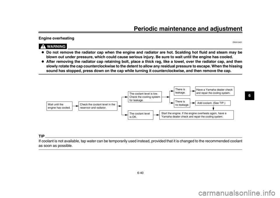
Engine overheating
WARNING
EWA10401
Do not remove the radiator cap when the engine and radiator are hot. Scalding hot fluid and steam may be
blown out under pressure, which could cause serious injury. Be sure to wait until the engine has cooled.
After removing the radiator cap retaining bolt, place a thick rag, like a towel, over the radiator cap, and then
slowly rotate the cap counterclockwise to the detent
to allow any residual pressure to escape. When the hissingsound has stopped, press down on the cap while turning it counterclockwise, and then remove the cap.
TIPIf coolant is not available, tap water can be temporarily used instead, provided that it is changed to the recommended coolantas soon as possible.
Wait until the
engine has cooled.
Check the coolant level in the
reservoir and radiator.
The coolant level
is OK.The coolant level is low.
Check the cooling system
for leakage.
Have a Yamaha dealer checkand repair the cooling system.Add coolant. (See TIP.)
Start the engine. If the engine overheats again,
have a
Yamaha dealer check
and repair the cooling system.
There is
leakage.
There is
no leakage.
2PP-9-E3.book 40 ページ 2016年9月13日 火曜日 午前9時7分
Page 111 of 114

10-1
1
2
3
4
5
6
7
8
91011
12
Index
AABS ...................................................... 3-21
ABS warning light ................................... 3-4
Air filter element.................................... 6-17
Auxiliary DC connector ......................... 3-39
Auxiliary DC jack .................................. 3-39
Auxiliary lights....................................... 6-35BBattery .................................................. 6-31
Brake and clutch levers, checking and lubricating .................................... 6-28
Brake and shift pedals, checking and lubricating .................................... 6-28
Brake fluid, changing ............................ 6-24
Brake fluid level, checking .................... 6-23
Brake lever ........................................... 3-20
Brake lever free play, checking ............ 6-21
Brake light switches .............................. 6-22
Brake pedal .......................................... 3-21
Brake/tail light ....................................... 6-36CCables, checking and lubricating .......... 6-27
Canister ................................................ 6-11
Care ........................................................ 7-1
Catalytic converter ................................ 3-27
Centerstand and sidestand, checking and lubricating ..................... 6-29
Clutch lever........................................... 3-20
Clutch lever free play, adjusting ........... 6-21
Coolant ................................................. 6-14DData recording, vehicle ........................... 9-2
Diagnostic connecto r .............................. 9-2
Dimmer/Pass switch ............................. 3-18 D-mode (drive mode) ............................ 3-17
Drive chain, cleaning
and lubricating .... 6-26
Drive chain slack ................................... 6-25
EEngine break-in ....................................... 5-3
Engine idling speed, checking............... 6-17
Engine oil and oil filter cartridge ............ 6-11
Engine serial number ..............................9-1
Engine trouble warning light .................... 3-4FFront and rear brake pads, checking .... 6-22
Front fork, adjusting .............................. 3-33
Front fork, checking............................... 6-30
Fuel ....................................................... 3-25
Fuel consumption, tips for reducing ........5-3
Fuel tank cap......................................... 3-24
Fuel tank overflow hose ........................ 3-27
Fuses, replacing .................................... 6-33HHandlebar position, adjusting ................ 3-33
Handlebar switches ............................... 3-18
Hazard switch........................................ 3-19
Headlight beams, adjusting ................... 3-33
Headlights ............................................. 6-35
Helmet holder ........................................ 3-31
High beam indicator light .........................3-4
Horn switch ........................................... 3-19IIdentification numbers .............................9-1
Ignition circuit cut-off system ................. 3-37
Immobilizer system ................................. 3-1
Immobilizer system indicator light ........... 3-5
Indicator lights and warning lights ........... 3-4
LLicense plate light bul b, replacing......... 6-37
Luggage strap holders .......................... 3-36MMain switch/steering lock ........................ 3-2
Maintenance and lubrication, periodic .... 6-5
Maintenance, emission control system ... 6-3
Matte color, caution ................................ 7-1
Menu switch .......................................... 3-19
Model label ............................................. 9-2
Multi-function meter unit ......................... 3-6NNeutral indicator light .............................. 3-4OOil level warning light .............................. 3-4PPanel, removing and installing ................ 6-9
Parking.................................................... 5-4
Part locations .......................................... 2-1RRider seat height, adjusting .................. 3-29SSafety information ................................... 1-1
Seats..................................................... 3-28
Select switch ......................................... 3-19
Shifting .................................................... 5-2
Shift pedal ............................................. 3-20
Shock absorber assembly, adjusting .... 3-35
Sidestand .............................................. 3-37
Spark plugs, checking ........................... 6-10
Specifications.......................................... 8-1
Starting the engine.................................. 5-1
Steering, checking ................................ 6-31
Stop/Run/Start switch ........................... 3-19
2PP-9-E3.book 1 ページ 2016年9月13日 火曜日 午前9時7分