clock YAMAHA NIKEN 2018 Owners Manual
[x] Cancel search | Manufacturer: YAMAHA, Model Year: 2018, Model line: NIKEN, Model: YAMAHA NIKEN 2018Pages: 106, PDF Size: 9.44 MB
Page 19 of 106
Instrument and control functions
3-4
3
Ri
ght
EAU73921
Dimmer/Pass switch “ / /PASS”
Set this switch to “ ” for the high
beam and to “ ” for the low beam.
To flash the high beam, push the pass
side “PASS” of the switch while the
headlights are on low beam.
EAU66040
Turn si gnal switch “ / ”
To signal a right-hand turn, push this
switch to “ ”. To signal a left-hand
turn, push this switch to “ ”. When
released, the switch returns to the cen- ter position. To cancel the turn signal
lights, push the switch in after it has re-
turned to the center position.
EAU66030
Horn switch “ ”
Press this switch to sound the horn.
EAU66060
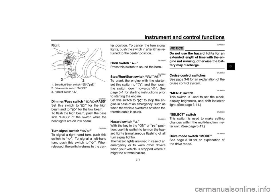
Stop/Run/Start switch “ / / ”
To crank the engine with the starter,
set this switch to “ ”, and then push
the switch down towards “ ”. See
page 5-1 for starting instructions prior
to starting the engine.
Set this switch to “ ” to stop the en-
gine in case of an emergency, such as
when the vehicle overturns or when the
throttle cable is stuck.
EAU66010
Hazar
d switch “ ”
With the key in the “ON” or “ ” posi-
tion, use this switch to turn on the haz-
ard lights (simultaneous flashing of all
turn signal lights).
The hazard lights are used in case of an
emergency or to warn other drivers
when your vehicle is stopped where it
might be a traffic hazard.
NOTICE
ECA10062
Do not use the hazar d lig hts for an
exten ded len gth of time with the en-
g ine not runnin g, otherwise the bat-
tery may d ischarge.
EAU84250
Cruise control switches
See page 3-8 for an explanation of the
cruise control system.
EAU84520
“MENU” switch
This switch is used to set the clock,
display brightness, and shift indicator
light. (See page 3-11.)
EAU84530
“SELECT” switch
This switch is used to make setting
changes within the multi-function me-
ter unit. (See page 3-11.)
EAU84260
Drive mo de switch “MODE”
See page 3-18 for an explanation of
the drive mode.
1. Stop/Run/Start switch “ / / ”
2. Drive mode switch “MODE”
3. Hazard switch “ ”
1
3
2
UBD5E0E0.book Page 4 Wednesday, April 25, 2018 2:23 PM
Page 26 of 106
Instrument and control functions
3-11
3
EAU84540
Multi-function meter unit
WARNING
EWA12423
Be sure to stop the vehicle before
makin g any settin g chan ges to the
multi-function meter unit. Chan gin g
settin gs while ri din g can d istract the
operator an d increase the risk of an
acci dent.
The multi-function meter unit is
equipped with the following:
speedometer
tachometer
clock
fuel meter
eco indicator
transmission gear display
drive mode display
TCS display
QS indicator
multi-function display
brightness and shift light control
modeTIPThe multi-function meter unit can
be set to kilometers or miles. To
switch between kilometers and
miles, set the multi-function dis-
play to the odometer, and then
push the “RESET” button for one
second.
“ ” does not function.
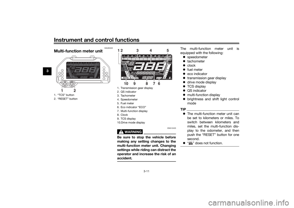
1. “TCS” button
2. “RESET” button
1
2
1. Transmission gear display
2. QS indicator
3. Tachometer
4. Speedometer
5. Fuel meter
6. Eco indicator “ECO”
7. Multi-function display
8. Clock
9. TCS display
10.Drive mode display
3
4
5
12
6
7
8
9
10
UBD5E0E0.book Page 11 Wednesday, April 25, 2018 2:23 PM
Page 27 of 106
Instrument and control functions
3-12
3
Spee
dometer
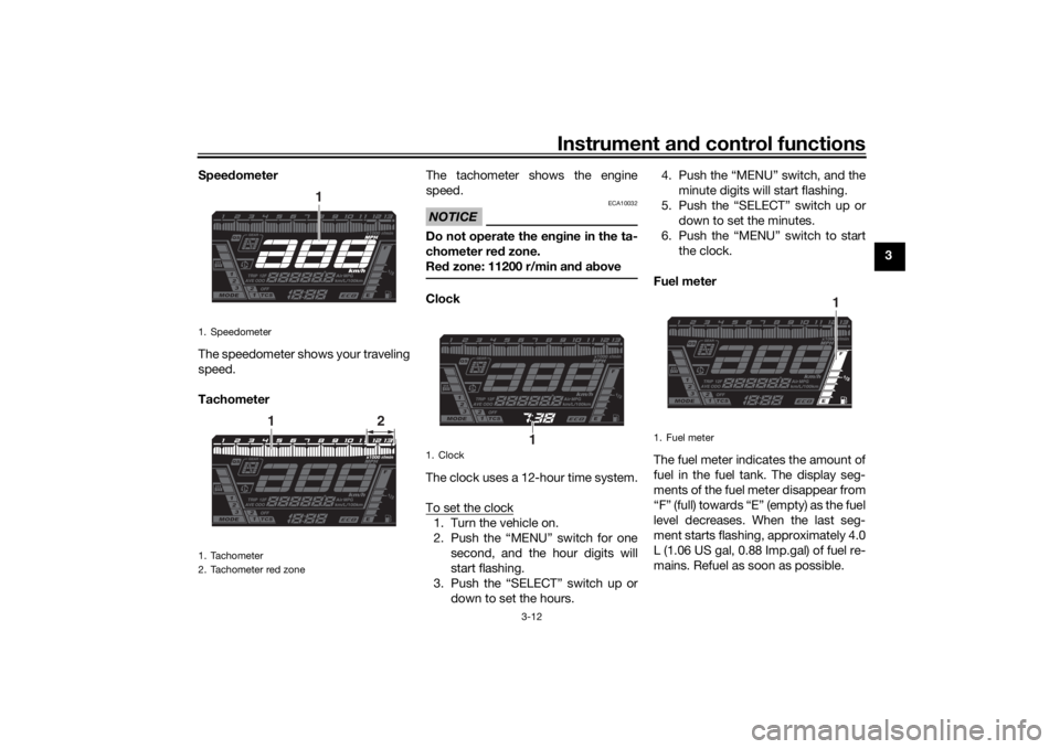
The speedometer shows your traveling
speed.
Tachometer The tachometer shows the engine
speed.
NOTICE
ECA10032
Do not operate the en
gine in the ta-
chometer red zone.
Re d zone: 11200 r/min an d a boveClock
The clock uses a 12-hour time system.
To set the clock1. Turn the vehicle on.
2. Push the “MENU” switch for one
second, and the hour digits will
start flashing.
3. Push the “SELECT” switch up or down to set the hours. 4. Push the “MENU” switch, and the
minute digits will start flashing.
5. Push the “SELECT” switch up or down to set the minutes.
6. Push the “MENU” switch to start the clock.
Fuel meter
The fuel meter indicates the amount of
fuel in the fuel tank. The display seg-
ments of the fuel meter disappear from
“F” (full) towards “E” (empty) as the fuel
level decreases. When the last seg-
ment starts flashing, approximately 4.0
L (1.06 US gal, 0.88 Imp.gal) of fuel re-
mains. Refuel as soon as possible.
1. Speedometer
1. Tachometer
2. Tachometer red zone
1
1
2
1. Clock
1
1. Fuel meter
1
UBD5E0E0.book Page 12 Wednesday, April 25, 2018 2:23 PM
Page 38 of 106
Instrument and control functions
3-23
3
excessive rear wheel spin is de-
tected while riding.
a wheel is rotated by external forc-
es with the vehicle power on (such
as when performing mainte-
nance).
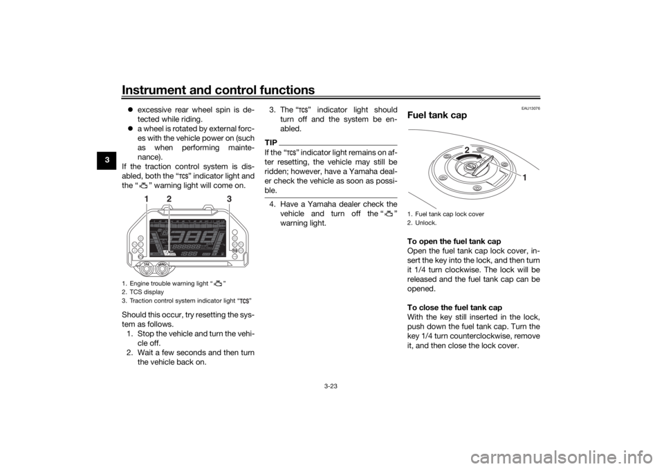
If the traction control system is dis-
abled, both the “ ” indicator light and
the “ ” warning light will come on.
Should this occur, try resetting the sys-
tem as follows. 1. Stop the vehicle and turn the vehi- cle off.
2. Wait a few seconds and then turn the vehicle back on. 3. The “ ” indicator light should
turn off and the system be en-
abled.
TIPIf the “ ” indicator light remains on af-
ter resetting, the vehicle may still be
ridden; however, have a Yamaha deal-
er check the vehicle as soon as possi-
ble.4. Have a Yamaha dealer check thevehicle and turn off the “ ”
warning light.
EAU13076
Fuel tank capTo open the fuel tank cap
Open the fuel tank cap lock cover, in-
sert the key into the lock, and then turn
it 1/4 turn clockwise. The lock will be
released and the fuel tank cap can be
opened.
To close the fuel tank cap
With the key still inserted in the lock,
push down the fuel tank cap. Turn the
key 1/4 turn counterclockwise, remove
it, and then close the lock cover.
1. Engine trouble warning light “ ”
2. TCS display
3. Traction control system indicator light “ ”
3
2
1
1. Fuel tank cap lock cover
2. Unlock.
1
2
UBD5E0E0.book Page 23 Wednesday, April 25, 2018 2:23 PM
Page 42 of 106
Instrument and control functions
3-27
3
NOTICE
ECA10702
Use only unlea ded g asoline. The use
of lead ed g asoline will cause unre-
pairab le damag e to the catalytic
converter.
EAU84580
SeatsPassen ger seat
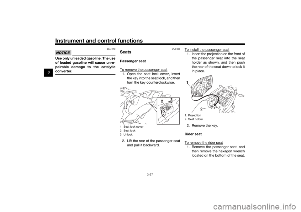
To remove the passenger seat1. Open the seat lock cover, insert the key into the seat lock, and then
turn the key counterclockwise.
2. Lift the rear of the passenger seat and pull it backward. To install the passenger seat
1. Insert the projection on the front of
the passenger seat into the seat
holder as shown, and then push
the rear of the seat down to lock it
in place.
2. Remove the key.
Ri der seat
To remove the rider seat1. Remove the passenger seat, and then remove the hexagon wrench
located on the bottom of the seat.
1. Seat lock cover
2. Seat lock
3. Unlock.
3
2
1
1. Projection
2. Seat holder1
2
UBD5E0E0.book Page 27 Wednesday, April 25, 2018 2:23 PM
Page 89 of 106
Periodic maintenance an d a djustment
6-31
6
EAU84650
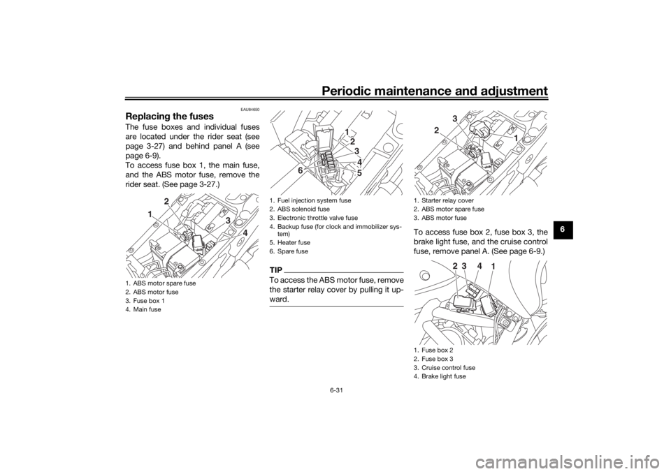
Replacin g the fusesThe fuse boxes and individual fuses
are located under the rider seat (see
page 3-27) and behind panel A (see
page 6-9).
To access fuse box 1, the main fuse,
and the ABS motor fuse, remove the
rider seat. (See page 3-27.)
TIPTo access the ABS motor fuse, remove
the starter relay cover by pulling it up-
ward.
To access fuse box 2, fuse box 3, the
brake light fuse, and the cruise control
fuse, remove panel A. (See page 6-9.)
1. ABS motor spare fuse
2. ABS motor fuse
3. Fuse box 1
4. Main fuse
1 2
34
1. Fuel injection system fuse
2. ABS solenoid fuse
3. Electronic throttle valve fuse
4. Backup fuse (for clock and immobilizer sys-tem)
5. Heater fuse
6. Spare fuse
1234
65
1. Starter relay cover
2. ABS motor spare fuse
3. ABS motor fuse
1. Fuse box 2
2. Fuse box 3
3. Cruise control fuse
4. Brake light fuse
2 3
1
2
3
41
UBD5E0E0.book Page 31 Wednesday, April 25, 2018 2:23 PM
Page 94 of 106
Periodic maintenance an d a djustment
6-36
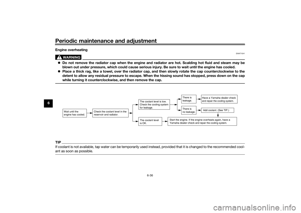
6 En
gine overheatin g
WARNING
EWAT1041
Do not remove the ra diator cap when the en gine an d ra diator are hot. Scal din g hot flui d an d steam may be
b lown out un der pressure, which coul d cause serious injury. Be sure to wait until the en gine has coole d.
Place a thick ra g, like a towel, over the ra diator cap, an d then slowly rotate the cap counterclockwise to the
d etent to allow any resi dual pressure to escape. When the hissin g soun d has stoppe d, press d own on the cap
while turnin g it counterclockwise, an d then remove the cap.TIPIf coolant is not available, tap water can be temporarily used instead, provided that it is changed to the recommended cool-
ant as soon as possible.
Wait until the
engine has cooled.
Check the coolant level in the
reservoir and radiator.
The coolant level
is OK.The coolant level is low.
Check the cooling system
for leakage.
Have a Yamaha dealer checkand repair the cooling system.Add coolant. (See TIP.)
Start the engine. If the engine overheats again,
have a
Yamaha dealer check
and repair the cooling system.
There is
leakage.
There is
no leakage.
UBD5E0E0.book Page 36 Wednesday, April 25, 2018 2:23 PM