clutch YAMAHA NIKEN GT 2019 Owners Manual
[x] Cancel search | Manufacturer: YAMAHA, Model Year: 2019, Model line: NIKEN GT, Model: YAMAHA NIKEN GT 2019Pages: 108, PDF Size: 9.98 MB
Page 6 of 108

Table of contentsSafety information ............................ 1-1
Description ....................................... 2-1
Left view ......................................... 2-1
Right view ....................................... 2-2
Controls and instruments ............... 2-3
Instrument an d control functions ... 3-1
Immobilizer system......................... 3-1
Main switch/steering lock............... 3-2
Handlebar switches ........................ 3-3
Indicator lights and warning lights............................................ 3-5
Cruise control system..................... 3-8
Multi-function meter unit .............. 3-11
D-mode (drive mode).................... 3-19
Clutch lever .................................. 3-19
Shift pedal .................................... 3-20
Quick shift system ........................ 3-20
Brake lever.................................... 3-21
Brake pedal .................................. 3-21
ABS .............................................. 3-21
Traction control system ................ 3-22
Fuel tank cap ................................ 3-24
Fuel ............................................... 3-25
Fuel tank overflow hose ............... 3-27
Catalytic converter ....................... 3-27
Seats ............................................ 3-28
Helmet holding cable.................... 3-29
Storage compartment .................. 3-30
Rear view mirrors.......................... 3-31 Adjusting the front fork ................. 3-31
Adjusting the shock absorber
assembly.................................... 3-32
Auxiliary DC jacks ......................... 3-34
Sidestand ...................................... 3-35
Ignition circuit cut-off system ....... 3-35
For your safety – pre-operation
checks ............................................... 4-1
Operation an d important ri din g
points ................................................. 5-1
Starting the engine .......................... 5-1
Shifting ............................................ 5-2
Tips for reducing fuel consumption ................................ 5-4
Engine break-in ............................... 5-4
Parking ............................................ 5-5
Perio dic maintenance an d
a d justment ........................................ 6-1
Tool kit ............................................ 6-2
Periodic maintenance charts .......... 6-3
Periodic maintenance chart for the emission control system .............. 6-3
General maintenance and
lubrication chart ........................... 6-5
Removing and installing the panel ............................................ 6-9
Checking the spark plugs ............. 6-10
Canister ......................................... 6-11 Engine oil ...................................... 6-11
Why Yamalube.............................. 6-13
Coolant ......................................... 6-14
Air filter element ............................ 6-15
Checking the engine idling
speed ........................................ 6-15
Checking the throttle grip free play ............................................ 6-16
Valve clearance............................. 6-16
Tires .............................................. 6-16
Cast wheels .................................. 6-19
Adjusting the clutch lever free play ............................................ 6-19
Checking the brake lever free
play ............................................ 6-20
Brake light switches ..................... 6-20
Checking the front and rear brake pads ................................ 6-21
Checking the brake fluid level ...... 6-22
Changing the brake fluid .............. 6-23
Drive chain slack........................... 6-23
Cleaning and lubricating the drive chain ................................. 6-25
Checking and lubricating the cables ........................................ 6-25
Checking and lubricating the
throttle grip and cable ............... 6-26
Checking and lubricating the brake and shift pedals............... 6-26
Checking and lubricating the brake and clutch levers ............. 6-27UB5BE0E0.book Page 1 Friday, September 7, 2018 10:34 AM
Page 15 of 108
Description
2-3
2
EAU10431
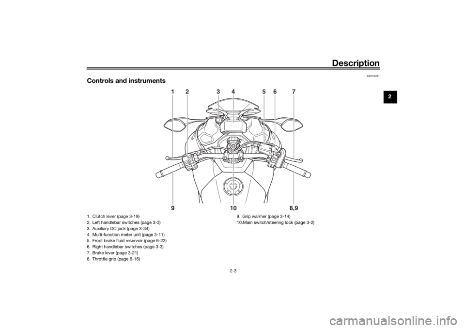
Controls and instruments
1
2
7
6
5
3
4
8,9
9
10
1. Clutch lever (page 3-19)
2. Left handlebar switches (page 3-3)
3. Auxiliary DC jack (page 3-34)
4. Multi-function meter unit (page 3-11)
5. Front brake fluid reservoir (page 6-22)
6. Right handlebar switches (page 3-3)
7. Brake lever (page 3-21)
8. Throttle grip (page 6-16) 9. Grip warmer (page 3-14)
10.Main switch/steering lock (page 3-2)
UB5BE0E0.book Page 3 Friday, September 7, 2018 10:34 AM
Page 25 of 108
Instrument and control functions
3-10
3
Apply the front or rear brake.
Squeeze the clutch lever.
Use the shift pedal.
Push the power switch to turn off the
cruise control system. The “ ” indica-
tor light and the “SET” indicator light
will go off.
TIPTraveling speed decreases as soon as
the cruise control system is deactivat-
ed; unless the throttle grip is turned.Usin g the resume function
Push the “RES+” side of the cruise
control setting switch to reactivate the
cruise control system. The traveling
speed will return to the previously set
cruising speed. The “SET” indicator
light will come on.
WARNING
EWA16351
It is d angerous to use the resume
function when the previously set
cruisin g speed is too hi gh for current
con ditions.
TIPPushing the power switch while the
system is operating will turn the sys-
tem off completely and erase the previ-
ously set cruising speed. You will not
be able to use the resume function until
a new cruising speed has been set.Automatic deactivation of the cruisecontrol systemThe cruise control system for this mod-
el is electronically controlled and is
linked with the other control systems.
The cruise control system will auto-
matically become deactivated under
the following conditions:
The cruise control system is not
able to maintain the set cruising
speed.
Wheel slip or wheel spin is detect-
ed. (If the traction control system
has not been turned off, the trac-
tion control system will work.)
The start/engine stop switch is set
to the “ ” position.
The engine stalls.
The sidestand is lowered. When traveling with a set cruising
speed, if the cruise control system is
deactivated under the above condi-
tions, the “ ” indicator light will go off
and the “SET” indicator light will flash
for 4 seconds, and then go off.
When not traveling with a set cruising
speed, if the start/engine stop switch is
set to the “ ” position, the engine
stalls, or the sidestand is lowered, then
the “ ” indicator light will go off (the
“SET” indicator light will not flash).
If the cruise control system is automat-
ically deactivated, please stop and
confirm that your vehicle is in good op-
erating condition.
Before using the cruise control system
again, activate it using the power
switch.
TIPIn some cases, the cruise control sys-
tem may not be able to maintain the set
cruising speed when the vehicle is
traveling uphill or downhill.
When the vehicle is traveling up-
hill, the actual traveling speed may
become lower than the set cruis-
UB5BE0E0.book Page 10 Friday, September 7, 2018 10:34 AM
Page 34 of 108
Instrument and control functions
3-19
3
EAU84550
D-mo de ( drive mo de)D-mode is an electronically controlled
engine performance system.
WARNING
EWA18440
Do not chan ge the d rive mo de while
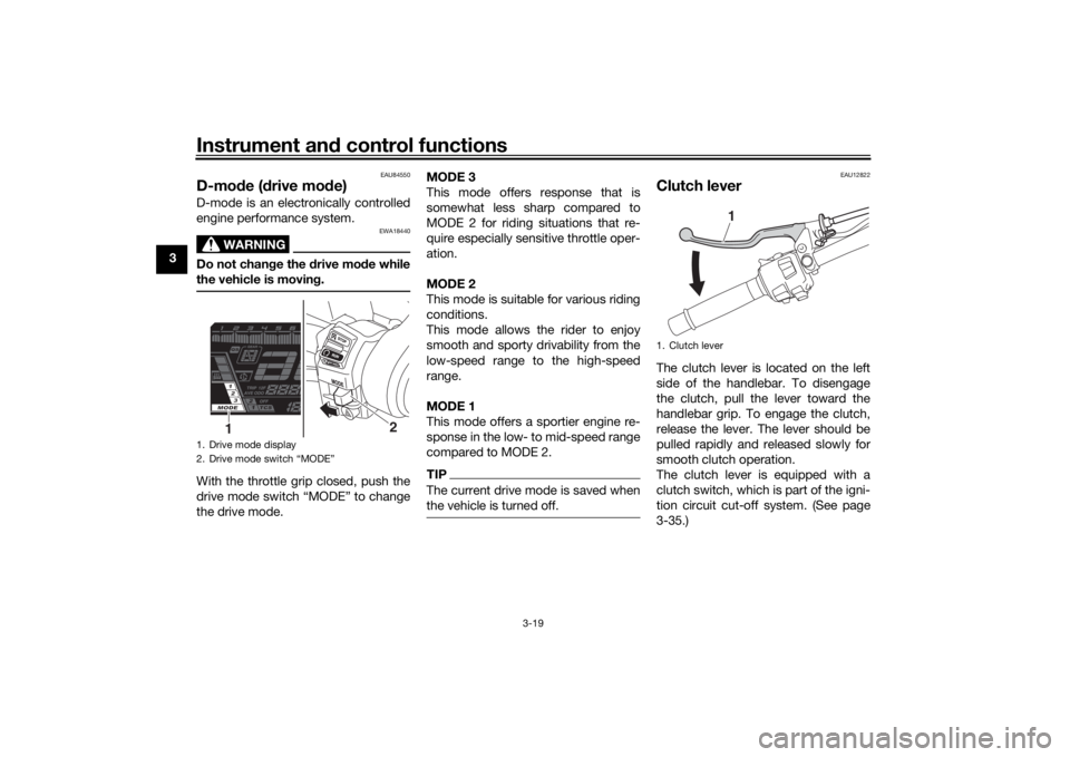
the vehicle is movin g.With the throttle grip closed, push the
drive mode switch “MODE” to change
the drive mode. MODE 3
This mode offers response that is
somewhat less sharp compared to
MODE 2 for riding situations that re-
quire especially sensitive throttle oper-
ation.
MODE 2
This mode is suitable for various riding
conditions.
This mode allows the rider to enjoy
smooth and sporty drivability from the
low-speed range to the high-speed
range.
MODE 1
This mode offers a sportier engine re-
sponse in the low- to mid-speed range
compared to MODE 2.
TIPThe current drive mode is saved when
the vehicle is turned off.
EAU12822
Clutch leverThe clutch lever is located on the left
side of the handlebar. To disengage
the clutch, pull the lever toward the
handlebar grip. To engage the clutch,
release the lever. The lever should be
pulled rapidly and released slowly for
smooth clutch operation.
The clutch lever is equipped with a
clutch switch, which is part of the igni-
tion circuit cut-off system. (See page
3-35.)
1. Drive mode display
2. Drive mode switch “MODE”
2
1
1. Clutch lever
1
UB5BE0E0.book Page 19 Friday, September 7, 2018 10:34 AM
Page 35 of 108
Instrument and control functions
3-20
3
EAU84321
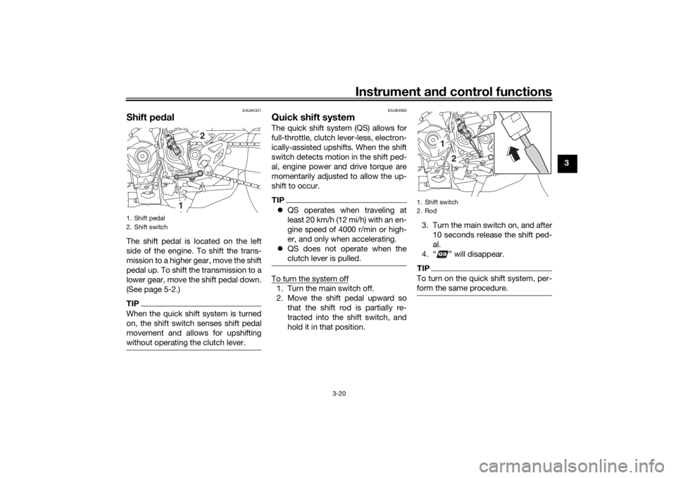
Shift pe dalThe shift pedal is located on the left
side of the engine. To shift the trans-
mission to a higher gear, move the shift
pedal up. To shift the transmission to a
lower gear, move the shift pedal down.
(See page 5-2.)TIPWhen the quick shift system is turned
on, the shift switch senses shift pedal
movement and allows for upshifting
without operating the clutch lever.
EAU84560
Quick shift systemThe quick shift system (QS) allows for
full-throttle, clutch lever-less, electron-
ically-assisted upshifts. When the shift
switch detects motion in the shift ped-
al, engine power and drive torque are
momentarily adjusted to allow the up-
shift to occur.TIP QS operates when traveling at
least 20 km/h (12 mi/h) with an en-
gine speed of 4000 r/min or high-
er, and only when accelerating.
QS does not operate when the
clutch lever is pulled.To turn the system off1. Turn the main switch off.
2. Move the shift pedal upward so
that the shift rod is partially re-
tracted into the shift switch, and
hold it in that position. 3. Turn the main switch on, and after
10 seconds release the shift ped-
al.
4. “ ” will disappear.
TIPTo turn on the quick shift system, per-
form the same procedure.
1. Shift pedal
2. Shift switch
2
1
1. Shift switch
2. Rod
1
2
UB5BE0E0.book Page 20 Friday, September 7, 2018 10:34 AM
Page 50 of 108
Instrument and control functions
3-35
3
EAU15306
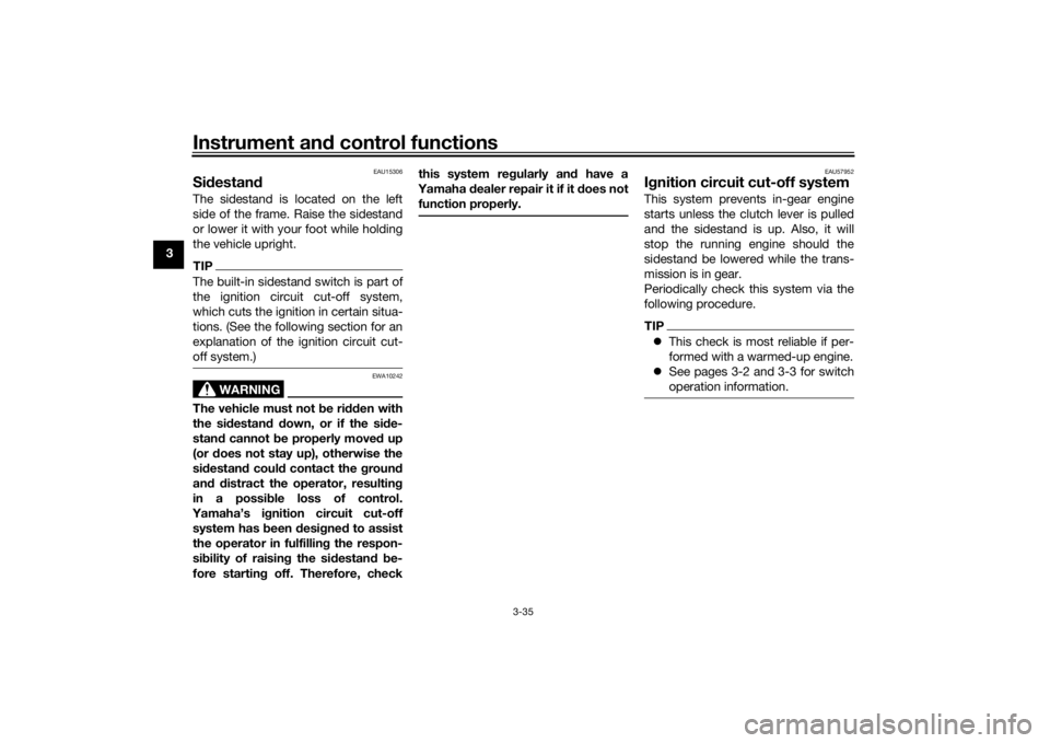
Si destan dThe sidestand is located on the left
side of the frame. Raise the sidestand
or lower it with your foot while holding
the vehicle upright.TIPThe built-in sidestand switch is part of
the ignition circuit cut-off system,
which cuts the ignition in certain situa-
tions. (See the following section for an
explanation of the ignition circuit cut-
off system.)
WARNING
EWA10242
The vehicle must not be ri dden with
the si destan d d own, or if the si de-
stan d cannot b e properly move d up
(or does not stay up), otherwise the
si destan d coul d contact the groun d
an d d istract the operator, resultin g
in a possi ble loss of control.
Yamaha’s ig nition circuit cut-off
system has been desi gne d to assist
the operator in fulfillin g the respon-
si bility of raisin g the si destan d b e-
fore startin g off. Therefore, check this system re
gularly an d have a
Yamaha dealer repair it if it does not
function properly.
EAU57952
I g nition circuit cut-off systemThis system prevents in-gear engine
starts unless the clutch lever is pulled
and the sidestand is up. Also, it will
stop the running engine should the
sidestand be lowered while the trans-
mission is in gear.
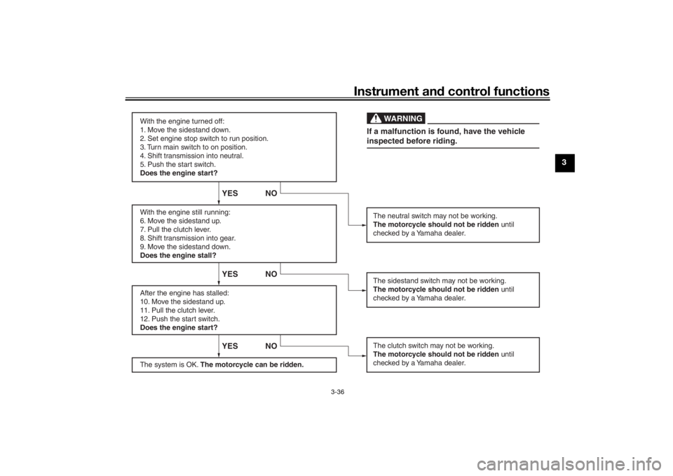
Periodically check this system via the
following procedure.TIP This check is most reliable if per-
formed with a warmed-up engine.
See pages 3-2 and 3-3 for switch
operation information.
UB5BE0E0.book Page 35 Friday, September 7, 2018 10:34 AM
Page 51 of 108
Instrument and control functions
3-36
3
With the engine turned off:
1. Move the sidestand down.
2. Set engine stop switch to run position.
3. Turn main switch to on position.
4. Shift transmission into neutral.
5. Push the start switch.
Does the engine start?
With the engine still running:
6. Move the sidestand up.
7. Pull the clutch lever.
8. Shift transmission into gear.
9. Move the sidestand down.
Does the engine stall?
After the engine has stalled:
10. Move the sidestand up.
11. Pull the clutch lever.
12. Push the start switch.
Does the engine start?
The system is OK. The motorcycle can be ridden.
YES NO YES NO YES NO
The neutral switch may not be working.
The motorcycle should not be ridden until
checked by a Yamaha dealer.
The clutch switch may not be working.
The motorcycle should not be ridden until
checked by a Yamaha dealer.The sidestand switch may not be working.
The motorcycle should not be ridden until
checked by a Yamaha dealer.If a malfunction is found, have the vehicle
inspected before riding.
WARNING
UB5BE0E0.book Page 36 Friday, September 7, 2018 10:34 AM
Page 53 of 108

For your safety – pre-operation checks
4-2
4
Rear brake • Check operation.
• If soft or spongy, have Yamaha dealer bleed hydraulic system.
• Check brake pads for wear.
• Replace if necessary.
• Check fluid level in reservoir.
• If necessary, add specified brake fluid to specified level.
• Check hydraulic system for leakage. 6-21, 6-22
Clutch • Check operation.
• Lubricate cable if necessary.
• Check lever free play.
• Adjust if necessary.
6-19
Throttle grip • Make sure that operation is smooth.
• Check throttle grip free play.
• If necessary, have Yamaha dealer adjust throttle grip free play and lubricate ca-
ble and grip housing. 6-16, 6-26
Control ca bles • Make sure that operation is smooth.
• Lubricate if necessary. 6-25
Drive chain • Check chain slack.
• Adjust if necessary.
• Check chain condition.
• Lubricate if necessary.
6-23, 6-25
Wheels an d tires • Check for damage.
• Check tire condition and tread depth.
• Check air pressure.
• Correct if necessary.
6-16, 6-19
Brake an d shift pe dals • Make sure that operation is smooth.
• Lubricate pedal pivoting points if necessary. 6-26
Brake an d clutch levers • Make sure that operation is smooth.
• Lubricate lever pivoting points if necessary.
6-27
Centerstan d, si destan d • Make sure that operation is smooth.
• Lubricate pivots if necessary.
6-27
ITEM CHECKS PAGE
UB5BE0E0.book Page 2 Friday, September 7, 2018 10:34 AM
Page 55 of 108
Operation and important ri din g points
5-1
5
EAU15952
Read the Owner’s Manual carefully to
become familiar with all controls. If
there is a control or function you do not
understand, ask your Yamaha dealer.
WARNING
EWA10272
Failure to familiarize yourself with
the controls can lead to loss of con-
trol, which coul d cause an acci dent
or injury.
EAUM3632
TIPThis model is equipped with: a lean angle sensor. This sensor
stops the engine in case of a vehi-
cle turnover. If this happens, the
engine trouble warning light will
come on, but this is not a malfunc-
tion. Turn the vehicle power off
and then back on again to cancel
the warning light. Failing to do so
will prevent the engine from start-
ing even though the engine will
crank when pushing the start
switch.
an engine auto-stop system. The
engine stops automatically if left
idling for 20 minutes. If the engine
stops, simply push the start
switch to restart the engine.
EAU84620
Startin g the en gineUnder normal conditions, shift the
transmission into neutral before start-
ing the engine. To start the engine with
the transmission in gear, the sidestand
must be up and the clutch lever pulled.
To start the engine1. Set the engine stop switch to “ ”.
2. Turn the main switch to “ ”.
3. Confirm the following lights per-
form a circuit check. Coolant temperature warning
light
Oil level warning light
Engine trouble warning light
ABS warning light
Traction control system indi-
cator light
Cruise control indicator lights
Shift indicator light
Immobilizer system indicator
lightTIP The ABS warning light should go
off after reaching a speed of 10
km/h (6 mi/h) or higher.
UB5BE0E0.book Page 1 Friday, September 7, 2018 10:34 AM
Page 56 of 108
Operation and important rid ing points
5-2
5
The neutral position indicator light
should be on when the transmis-
sion is in neutral.
NOTICE
ECA24110
If a warnin g or in dicator li ght does
not work as d escribed a bove, have a
Yamaha dealer check the vehicle.4. Push the start switch “ ”.
Release the start switch when the
engine starts, or after 5 seconds.
Wait 10 seconds before pressing
the switch again to allow battery
voltage to restore.NOTICE
ECA11043
For maximum en gine life, never ac-
celerate har d when the en gine is
col d!
EAU84370
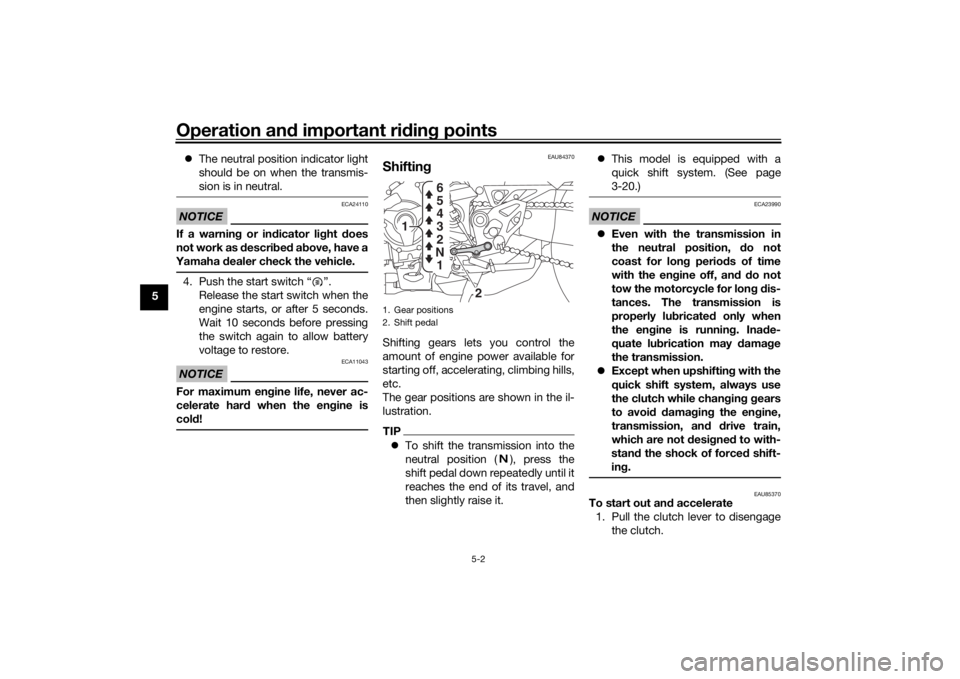
Shiftin gShifting gears lets you control the
amount of engine power available for
starting off, accelerating, climbing hills,
etc.
The gear positions are shown in the il-
lustration.TIPTo shift the transmission into the
neutral position ( ), press the
shift pedal down repeatedly until it
reaches the end of its travel, and
then slightly raise it.
This model is equipped with a
quick shift system. (See page
3-20.)
NOTICE
ECA23990
Even with the transmission in
the neutral position, do not
coast for lon g period s of time
with the eng ine off, and d o not
tow the motorcycle for lon g d is-
tances. The transmission is
properly lu bricated only when
the en gine is runnin g. Ina de-
quate lu brication may damag e
the transmission.
Except when upshiftin g with the
quick shift system, always use
the clutch while chan gin g g ears
to avoi d d amag ing the en gine,
transmission, an d drive train,
which are not desi gne d to with-
stan d the shock of forced shift-
in g.
EAU85370
To start out an d accelerate
1. Pull the clutch lever to disengage the clutch.
1. Gear positions
2. Shift pedal
2
1
1
N 2 3 4
5
6
UB5BE0E0.book Page 2 Friday, September 7, 2018 10:34 AM