ABS YAMAHA NMAX 125 2017 Owners Manual
[x] Cancel search | Manufacturer: YAMAHA, Model Year: 2017, Model line: NMAX 125, Model: YAMAHA NMAX 125 2017Pages: 94, PDF Size: 3.7 MB
Page 5 of 94

Table of contents
Safety information ............................1-1
Further safe-riding points ................1-5
Description ........................................2-1
Left view ..........................................2-1
Right view........................................2-2
Controls and instruments ................2-3
Instrument an d control functions ....3-1
Main switch/steering lock ...............3-1
Keyhole shutter ...............................3-2
Indicator lights and warning lights ............................................3-3
Multi-function meter unit .................3-4
Handlebar switches.........................3-9
Front brake lever ...........................3-10
Rear brake lever ............................3-11
ABS ...............................................3-11
Fuel tank cap.................................3-12
Fuel................................................3-13
Fuel tank overflow hose ................3-15
Catalytic converter ........................3-15
Seat ...............................................3-16
Storage compartments .................3-16
Sidestand ......................................3-17
Ignition circuit cut-off system........3-18
For your safety – pre-operation
checks ...............................................4-1
Operation an d important ri din g
points .................................................5-1
Starting the engine ..........................5-1
Starting off.......................................5-2
Acceleration and deceleration.........5-3
Braking ............................................5-3
Tips for reducing fuel consumption ................................5-4
Engine break-in ...............................5-4
Parking ............................................5-5
Perio dic maintenance an d
a d justment ........................................6-1
Owner’s tool kit ...............................6-2
Periodic maintenance chart for the emission control system ........6-3 General maintenance and
lubrication chart........................... 6-4
Removing and installing panels ...... 6-7
Checking the spark plug ................. 6-9
Engine oil and oil strainer.............. 6-10
Final transmission oil .................... 6-12
Coolant ......................................... 6-13
Air filter and V-belt case air filter elements ............................ 6-17
Checking the throttle grip free play ..................................... 6-19
Valve clearance ............................. 6-20
Tires .............................................. 6-20
Cast wheels .................................. 6-22
Checking the front and rear brake lever free play .................. 6-23
Checking the front and rear
brake pads................................. 6-24
Checking the brake fluid level....... 6-25
Changing the brake fluid............... 6-26
Checking the V-belt ...................... 6-26
Checking and lubricating the cables ........................................ 6-27
Checking and lubricating the throttle grip and cable ............... 6-27
Lubricating the front and rear
brake levers ............................... 6-28
Checking and lubricating the centerstand and sidestand ........ 6-28
Checking the front fork ................. 6-29
Checking the steering ................... 6-29
Checking the wheel bearings ....... 6-30
Battery .......................................... 6-30
Replacing the fuses ...................... 6-32
Headlight....................................... 6-33
Replacing an auxiliary light bulb ... 6-34
Brake light ..................................... 6-35
Replacing the taillight bulb ........... 6-35
Replacing a front turn signal light bulb .................................... 6-37
Replacing a rear turn signal
light bulb .................................... 6-38
Troubleshooting ............................ 6-39
Troubleshooting charts ................. 6-40
UBV3E0E0.book Page 1 Monday, September 26, 2016 3:42 PM
Page 17 of 94
Instrument and control functions
3-3
3
EAU4939B
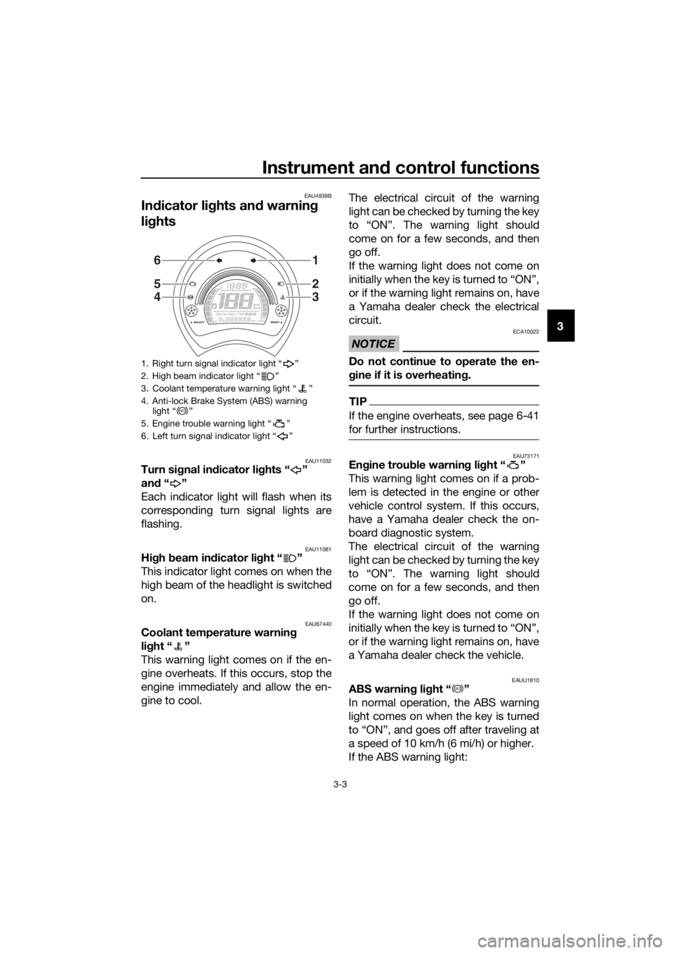
In dicator li ghts an d warnin g
li g hts
EAU11032Turn si gnal in dicator li ghts “ ”
an d“”
Each indicator light will flash when its
corresponding turn signal lights are
flashing.
EAU11081Hi gh beam in dicator li ght “ ”
This indicator light comes on when the
high beam of the headlight is switched
on.
EAU67440Coolant temperature warnin g
li g ht “ ”
This warning light comes on if the en-
gine overheats. If this occurs, stop the
engine immediately and allow the en-
gine to cool. The electrical circuit of the warning
light can be checked by turning the key
to “ON”. The warning light should
come on for a few seconds, and then
go off.
If the warning light does not come on
initially when the key is turned to “ON”,
or if the warning light remains on, have
a Yamaha dealer check the electrical
circuit.
NOTICE
ECA10022
Do not continue to operate the en-
g
ine if it is overheatin g.
TIP
If the engine overheats, see page 6-41
for further instructions.
EAU73171En gine trou ble warnin g li ght “ ”
This warning light comes on if a prob-
lem is detected in the engine or other
vehicle control system. If this occurs,
have a Yamaha dealer check the on-
board diagnostic system.
The electrical circuit of the warning
light can be checked by turning the key
to “ON”. The warning light should
come on for a few seconds, and then
go off.
If the warning light does not come on
initially when the key is turned to “ON”,
or if the warning light remains on, have
a Yamaha dealer check the vehicle.
EAUU1810ABS warnin g lig ht “ ”
In normal operation, the ABS warning
light comes on when the key is turned
to “ON”, and goes off after traveling at
a speed of 10 km/h (6 mi/h) or higher.
If the ABS warning light:
1. Right turn signal indicator light “ ”
2. High beam indicator light “ ”
3. Coolant temperature warning light “ ”
4. Anti-lock Brake System (ABS) warning light “ ”
5. Engine trouble warning light “ ”
6. Left turn signal indicator light “ ”
6
5
4
1
2
3
ABS
ABS
UBV3E0E0.book Page 3 Monday, September 26, 2016 3:42 PM
Page 18 of 94
Instrument and control functions
3-4
3
does not come on when the key is
turned to “ON”
comes on or flashes while riding
does not go off after traveling at a
speed of 10 km/h (6 mi/h) or high-
er
The ABS may not work correctly. If any
of the above occurs, have a Yamaha
dealer check the system as soon as
possible. (See page 3-11 for an expla-
nation of the ABS.)
WARNING
EWA16041
If the ABS warnin g li ght does not go
off after travelin g at a speed of 10
km/h (6 mi/h) or hi gher, or if the
warnin g li ght comes on or flashes
while ri din g, the brake system re-
verts to conventional brakin g. If ei-
ther of the a bove occurs, or if the
warnin g li ght does not come on at
all, use extra caution to avoi d possi-
b le wheel lock during emer gency
b rakin g. Have a Yamaha dealer
check the brake system an d electri-
cal circuits as soon as possi ble.
TIP
The ABS warning light may come on
while accelerating the engine with the
vehicle on its centerstand, but this
does not indicate a malfunction.
EAUN0983
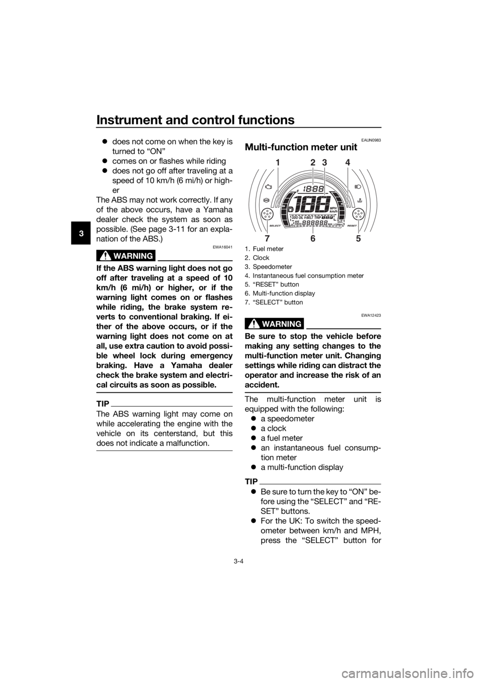
Multi-function meter unit
WARNING
EWA12423
Be sure to stop the vehicle before
makin g any settin g chan ges to the
multi-function meter unit. Chang ing
settin gs while ri din g can d istract the
operator an d increase the risk of an
acci dent.
The multi-function meter unit is
equipped with the following:
a speedometer
a clock
a fuel meter
an instantaneous fuel consump-
tion meter
a multi-function display
TIP
B e s u r e t o t u r n t h e k e y t o “ O N ” b e -
fore using the “SELECT” and “RE-
SET” buttons.
For the UK: To switch the speed-
ometer between km/h and MPH,
press the “SELECT” button for
1. Fuel meter
2. Clock
3. Speedometer
4. Instantaneous fuel consumption meter
5. “RESET” button
6. Multi-function display
7. “SELECT” button
2314
675
UBV3E0E0.book Page 4 Monday, September 26, 2016 3:42 PM
Page 25 of 94
Instrument and control functions
3-11
3
EAU12952
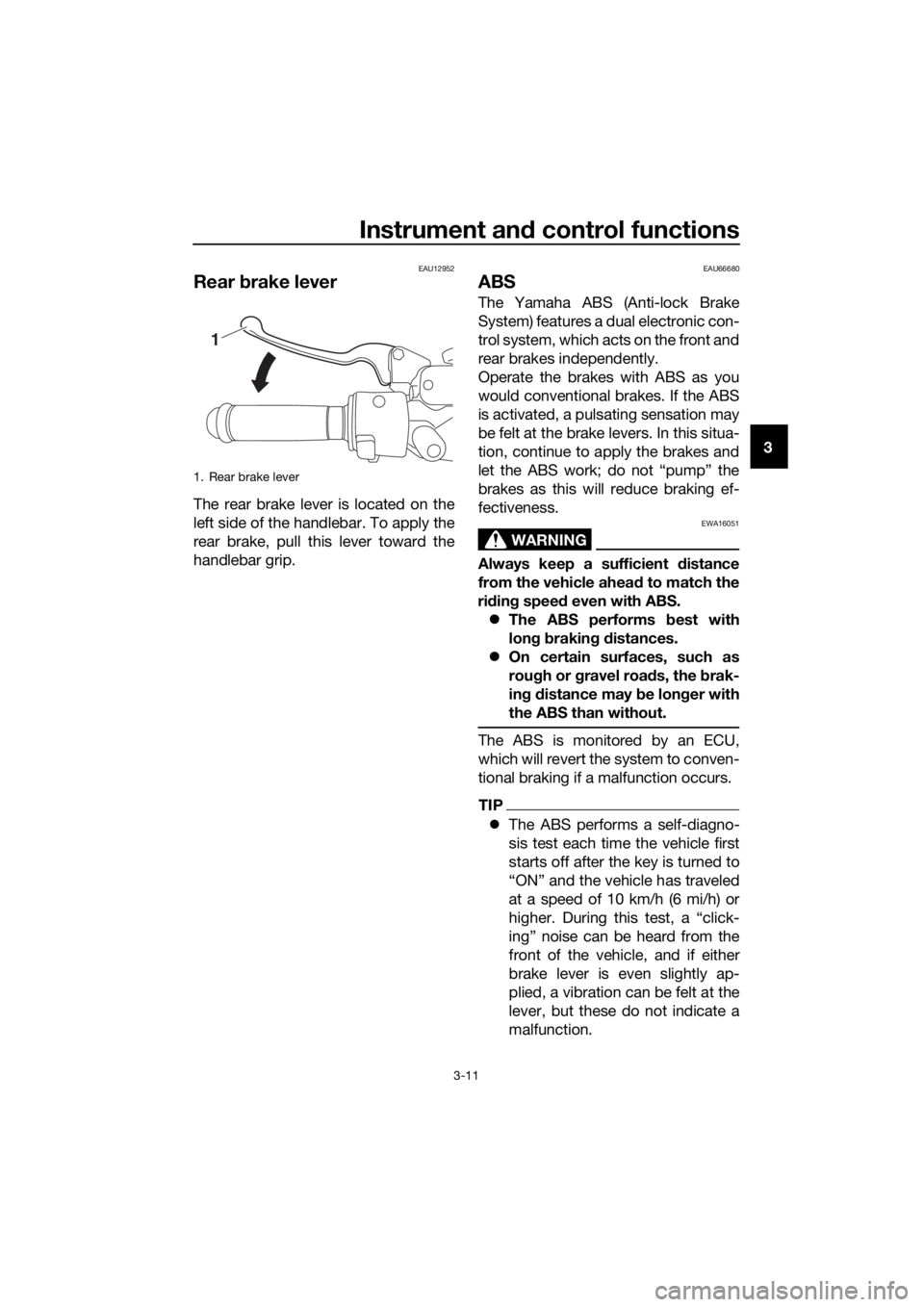
Rear brake lever
The rear brake lever is located on the
left side of the handlebar. To apply the
rear brake, pull this lever toward the
handlebar grip.
EAU66680
ABS
The Yamaha ABS (Anti-lock Brake
System) features a dual electronic con-
trol system, which acts on the front and
rear brakes independently.
Operate the brakes with ABS as you
would conventional brakes. If the ABS
is activated, a pulsating sensation may
be felt at the brake levers. In this situa-
tion, continue to apply the brakes and
let the ABS work; do not “pump” the
brakes as this will reduce braking ef-
fectiveness.
WARNING
EWA16051
Always keep a sufficient distance
from the vehicle ahea d to match the
ri din g speed even with ABS.
The ABS performs best with
lon g b rakin g d istances.
On certain surfaces, such as
rou gh or g ravel roa ds, the b rak-
in g d istance may be lon ger with
the ABS than without.
The ABS is monitored by an ECU,
which will revert the system to conven-
tional braking if a malfunction occurs.
TIP
The ABS performs a self-diagno-
sis test each time the vehicle first
starts off after the key is turned to
“ON” and the vehicle has traveled
at a speed of 10 km/h (6 mi/h) or
higher. During this test, a “click-
ing” noise can be heard from the
front of the vehicle, and if either
brake lever is even slightly ap-
plied, a vibration can be felt at the
lever, but these do not indicate a
malfunction.
1. Rear brake lever
1
UBV3E0E0.book Page 11 Monday, September 26, 2016 3:42 PM
Page 26 of 94
Instrument and control functions
3-12
3
This ABS has a test mode which
allows the owner to experience
the pulsation at the brake levers
when the ABS is operating. How-
ever, special tools are required, so
please consult your Yamaha deal-
er.
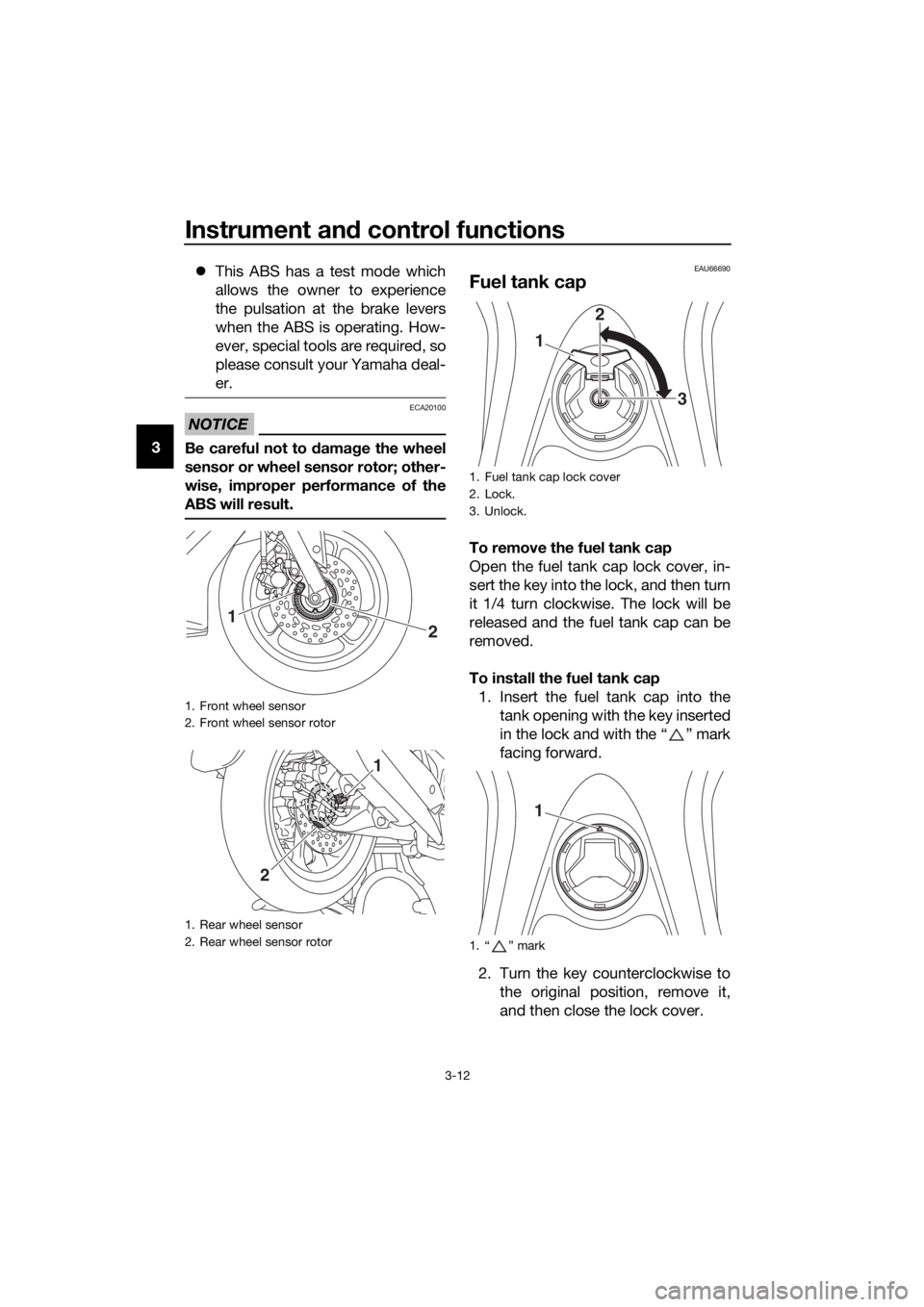
NOTICE
ECA20100
Be careful not to damag e the wheel
sensor or wheel sensor rotor; other-
wise, improper performance of the
ABS will result.
EAU66690
Fuel tank cap
To remove the fuel tank cap
Open the fuel tank cap lock cover, in-
sert the key into the lock, and then turn
it 1/4 turn clockwise. The lock will be
released and the fuel tank cap can be
removed.
To install the fuel tank cap 1. Insert the fuel tank cap into the tank opening with the key inserted
in the lock and with the “ ” mark
facing forward.
2. Turn the key counterclockwise to the original position, remove it,
and then close the lock cover.
1. Front wheel sensor
2. Front wheel sensor rotor
1. Rear wheel sensor
2. Rear wheel sensor rotor
2
1
1
2
1. Fuel tank cap lock cover
2. Lock.
3. Unlock.
1. “ ” mark
1 2
3
1
UBV3E0E0.book Page 12 Monday, September 26, 2016 3:42 PM
Page 36 of 94
Operation and important rid ing points
5-1
5
EAU15952
Read the Owner’s Manual carefully to
become familiar with all controls. If
there is a control or function you do not
understand, ask your Yamaha dealer.
WARNING
EWA10272
Failure to familiarize yourself with
the controls can lea d to loss of con-
trol, which coul d cause an acci dent
or injury.
EAU66721
Startin g the eng ine
NOTICE
ECA10251
See pag e 5-4 for en gine break-in in-
structions prior to operatin g the ve-
hicle for the first time.
In order for the ignition circuit cut-off
system to enable starting, the side-
stand must be up. See page 3-18 for more information. 1. Turn the main switch on. The engine trouble warning
light and the coolant temper-
ature warning light should
come on for a few seconds,
then go off.
The ABS warning light should
come on and stay on until the
vehicle reaches a traveling
speed of 10 km/h (6 mi/h).
NOTICE
ECA15486
If a warnin g li ght does not come on
initially when the main switch is
turne d on, or if a warnin g li ght re-
mains on, see pa ge 3-3 for the corre-
spon din g warnin g li ght circuit
check.
2. Close the throttle completely.
3. While applying the front or rear brake, push the start switch.
If the engine does not start, re-
lease the start switch, wait a few
seconds, and then try again. Each
starting attempt should be as
short as possible to preserve the
battery. Do not crank the engine
more than 10 seconds on any one
attempt.
UBV3E0E0.book Page 1 Monday, September 26, 2016 3:42 PM
Page 65 of 94
Periodic maintenance an d a djustment
6-25
6
EAU40262
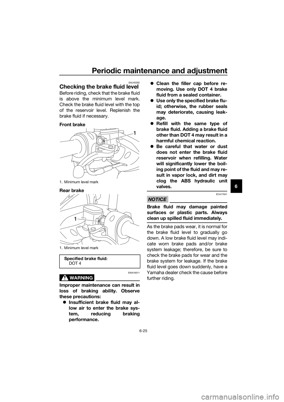
Checkin g the brake flui d level
Before riding, check that the brake fluid
is above the minimum level mark.
Check the brake fluid level with the top
of the reservoir level. Replenish the
brake fluid if necessary.
Front brake
Rear brake
WARNING
EWA16011
Improper maintenance can result in
loss of brakin g a bility. O bserve
these precautions: Insufficient brake flui d may al-
low air to enter the brake sys-
tem, re ducing brakin g
performance.
Clean the filler cap before re-
moving . Use only DOT 4 b rake
flui d from a seale d container.
Use only the specifie d b rake flu-
i d ; otherwise, the ru bber seals
may deteriorate, causin g leak-
a g e.
Refill with the same type of
brake flui d. A ddin g a brake flui d
other than DOT 4 may result in a
harmful chemical reaction.
Be careful that water or dust
d oes not enter the brake flui d
reservoir when refilling . Water
will si gnificantly lower the boil-
in g point of the flui d an d may re-
sult in vapor lock, an d d ir
t may
clo g the ABS hy draulic unit
valves.
NOTICE
ECA17641
Brake flui d may d amage painte d
surfaces or plastic parts. Always
clean up spille d flui d imme diately.
As the brake pads wear, it is normal for
the brake fluid level to gradually go
down. A low brake fluid level may indi-
cate worn brake pads and/or brake
system leakage; therefore, be sure to
check the brake pads for wear and the
brake system for leakage. If the brake
fluid level goes down suddenly, have a
Yamaha dealer check the cause before further riding.
1. Minimum level mark
1. Minimum level mark
Specified b rake flui d:
DOT 4
1
1
UBV3E0E0.book Page 25 Monday, September 26, 2016 3:42 PM
Page 72 of 94
Periodic maintenance an d a djustment
6-32
6
EAU66793
Replacin g the fuses
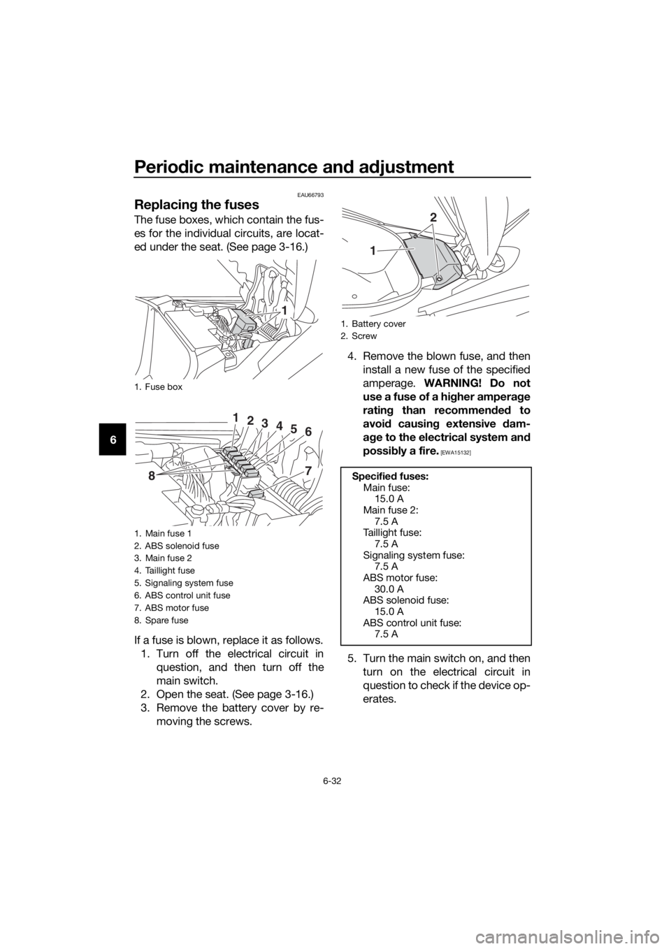
The fuse boxes, which contain the fus-
es for the individual circuits, are locat-
ed under the seat. (See page 3-16.)
If a fuse is blown, replace it as follows.
1. Turn off the electrical circuit in question, and then turn off the
main switch.
2. Open the seat. (See page 3-16.)
3. Remove the battery cover by re- moving the screws. 4. Remove the blown fuse, and then
install a new fuse of the specified
amperage. WARNING! Do not
use a fuse of a hi gher ampera ge
ratin g than recommen ded to
avoi d causin g extensive dam-
a g e to the electrical system an d
possi bly a fire.
[EWA15132]
5. Turn the main switch on, and then
turn on the electrical circuit in
question to check if the device op-
erates.
1. Fuse box
1. Main fuse 1
2. ABS solenoid fuse
3. Main fuse 2
4. Taillight fuse
5. Signaling system fuse
6. ABS control unit fuse
7. ABS motor fuse
8. Spare fuse
1
123456
78
1. Battery cover
2. Screw
Specified fuses:
Main fuse: 15.0 A
Main fuse 2:
7.5 A
Taillight fuse: 7.5 A
Signaling system fuse: 7.5 A
ABS motor fuse:
30.0 A
ABS solenoid fuse: 15.0 A
ABS control unit fuse: 7.5 A
1
2
UBV3E0E0.book Page 32 Monday, September 26, 2016 3:42 PM
Page 84 of 94
Scooter care and stora ge
7-3
7 Cleaning the windshield
Avoid using any alkaline or strong acid
cleaner, gasoline, brake fluid, or any
other solvent. Clean the windshield
with a cloth or sponge dampened with
a neutral detergent, and after cleaning,
thoroughly wash it off with water. For
additional cleaning, use Yamaha Wind-
shield Cleaner or other quality cleaner.
Some cleaning compounds for plastics
may leave scratches on surfaces of the
windshield. Before using them, make a
test by polishing an area which does
not affect your visibility.
After cleanin
g
1. Dry the scooter with a chamois or an absorbing cloth.
2. Use a chrome polish to shine chrome, aluminum and stainless-
steel parts, including the exhaust
system. (Even the thermally in-
duced discoloring of stainless-
steel exhaust systems can be re-
moved through polishing.)
3. To prevent corrosion, it is recom- mended to apply a corrosion pro-
tection spray on all metal,
including chrome- and nickel-plat-
ed, surfaces.
4. Use spray oil as a universal clean- er to remove any remaining dirt.
5. Touch up minor paint damage caused by stones, etc.
6. Wax all painted surfaces.
7. Let the scooter dry completely be- fore storing or covering it.
WARNING
EWA10943
Contaminants on the brakes or tires
can cause loss of control.
Make sure that there is no oil or
wax on the brakes or tires. If
necessary, clean the brake
d iscs an d b rake linin gs with a
re gular brake disc cleaner or
acetone, an d wash the tires with
warm water an d a mil d d eter-
g ent.
Before operatin g the scooter
test its brakin g performance
an d cornerin g b ehavior.
NOTICE
ECAU0022
Apply spray oil an d wax spar-
in gly an d make sure to wipe off
any excess.
Never apply oil or wax to any
rubber parts, plastic parts or
hea dlig ht, tailli ght and meter
lenses, but treat them with a
suita ble care prod uct.
Avoi d using abrasive polishin g
compoun ds as they will wear
away the paint.
TIP
Consult a Yamaha dealer for ad-
vice on what products to use.
Washing, rainy weather or humid
climates can cause the headlight
lens to fog. Turning the headlight
on for a short period of time will
help remove the moisture from the
lens.
UBV3E0E0.book Page 3 Monday, September 26, 2016 3:42 PM
Page 88 of 94

Specifications
8-2
8
Caster angle:26.0 °
Trail: 92 mm (3.6 in)
Front tire:
Type:Tubeless
Size: 110/70-13M/C 48P
Manufacturer/model:
DUNLOP/SCOOTSMART
Rear tire:
Type: Tubeless
Size: 130/70-13M/C 57P
Manufacturer/model:
DUNLOP/SCOOTSMART
Loa din g:
Maximum load:
168 kg (370 lb)
(Total weight of rider, passenger, cargo
and accessories)
Tire air pressure (measure d on col d
tires):
1 person:
Front:150 kPa (1.50 kgf/cm², 22 psi)
Rear:
rsons:2 pe Front:
150
kPa (1.50 kgf/cm², 22 psi)
Rear:
Front wheel:
Wheel type:
Cast wheel
Rim size: 13M/C x MT3.00
Rear wheel:
Wheel type:
Cast wheel
Rim size: 13M/C x MT3.50
Front brake:
Type:
Hydraulic single disc brake
Specified brake fluid: DOT 4
Rear brake:
Type:
Hydraulic single disc brake
Specified brake fluid:
DOT 4
Front suspension:
Type:Telescopic fork
Spring:
Coil spring
Shock absorber: Hydraulic damper
Wheel travel: 100 mm (3.9 in)
Rear suspension:
Type:
Unit swing
Spring: Coil spring
Shock absorber: Hydraulic damper
Wheel travel:
90 mm (3.5 in)
Electrical system:
System voltage:12 V
Ignition system:
TCI
Charging system: AC magneto
Battery:
Model:
YTZ7V
Voltage, capacity: 12 V, 6.0 Ah (10 HR)
Bul b watta ge:
Headlight:
LED
Brake/tail light: LED/10.0 W
Front turn signal light: 10.0 W
Rear turn signal light:
10.0 W
Auxiliary light: 5.0 W
Meter lighting: LED
High beam indicator light:
LED
UBV3E0E0.book Page 2 Monday, September 26, 2016 3:42 PM
250 kPa (2.50 kgf/cm², 36 psi)
250 kPa (2.50 kgf/cm², 36 psi)