clock YAMAHA NMAX 125 2017 Owners Manual
[x] Cancel search | Manufacturer: YAMAHA, Model Year: 2017, Model line: NMAX 125, Model: YAMAHA NMAX 125 2017Pages: 94, PDF Size: 3.7 MB
Page 18 of 94
Instrument and control functions
3-4
3
does not come on when the key is
turned to “ON”
comes on or flashes while riding
does not go off after traveling at a
speed of 10 km/h (6 mi/h) or high-
er
The ABS may not work correctly. If any
of the above occurs, have a Yamaha
dealer check the system as soon as
possible. (See page 3-11 for an expla-
nation of the ABS.)
WARNING
EWA16041
If the ABS warnin g li ght does not go
off after travelin g at a speed of 10
km/h (6 mi/h) or hi gher, or if the
warnin g li ght comes on or flashes
while ri din g, the brake system re-
verts to conventional brakin g. If ei-
ther of the a bove occurs, or if the
warnin g li ght does not come on at
all, use extra caution to avoi d possi-
b le wheel lock during emer gency
b rakin g. Have a Yamaha dealer
check the brake system an d electri-
cal circuits as soon as possi ble.
TIP
The ABS warning light may come on
while accelerating the engine with the
vehicle on its centerstand, but this
does not indicate a malfunction.
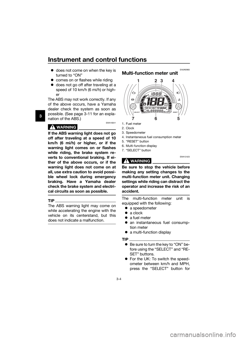
EAUN0983
Multi-function meter unit
WARNING
EWA12423
Be sure to stop the vehicle before
makin g any settin g chan ges to the
multi-function meter unit. Chang ing
settin gs while ri din g can d istract the
operator an d increase the risk of an
acci dent.
The multi-function meter unit is
equipped with the following:
a speedometer
a clock
a fuel meter
an instantaneous fuel consump-
tion meter
a multi-function display
TIP
B e s u r e t o t u r n t h e k e y t o “ O N ” b e -
fore using the “SELECT” and “RE-
SET” buttons.
For the UK: To switch the speed-
ometer between km/h and MPH,
press the “SELECT” button for
1. Fuel meter
2. Clock
3. Speedometer
4. Instantaneous fuel consumption meter
5. “RESET” button
6. Multi-function display
7. “SELECT” button
2314
675
UBV3E0E0.book Page 4 Monday, September 26, 2016 3:42 PM
Page 19 of 94
Instrument and control functions
3-5
3
one second when the multi-func-
tion meter is in odometer mode,
tripmeter 1, or tripmeter 2 mode .
Speed
ometer
The speedometer shows the vehicle’s
traveling speed.
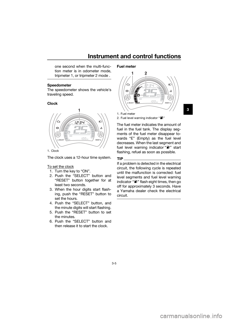
Clock
The clock uses a 12-hour time system.
To set the clock
1. Turn the key to “ON”.
2. Push the “SELECT” button and “RESET” button together for at
least two seconds.
3. When the hour digits start flash- ing, push the “RESET” button to
set the hours.
4. Push the “SELECT” button, and
the minute digits will start flashing.
5. Push the “RESET” button to set the minutes.
6. Push the “SELECT” button and then release it to start the clock. Fuel meter
The fuel meter indicates the amount of
fuel in the fuel tank. The display seg-
ments of the fuel meter disappear to-
wards “E” (Empty) as the fuel level
decreases. When the last segment and
fuel level warning indicator “ ” start
flashing, refuel as soon as possible.
TIP
If a problem is detected in the electrical
circuit, the following cycle is repeated
until the malfunction is corrected: fuel
level segments and fuel level warning
indicator “ ” flash eight times, then go
off for approximately 3 seconds. Have
a Yamaha dealer check the electrical
circuit.
1. Clock
11. Fuel meter
2. Fuel level warning indicator “ ”
12
UBV3E0E0.book Page 5 Monday, September 26, 2016 3:42 PM
Page 26 of 94
Instrument and control functions
3-12
3
This ABS has a test mode which
allows the owner to experience
the pulsation at the brake levers
when the ABS is operating. How-
ever, special tools are required, so
please consult your Yamaha deal-
er.
NOTICE
ECA20100
Be careful not to damag e the wheel
sensor or wheel sensor rotor; other-
wise, improper performance of the
ABS will result.
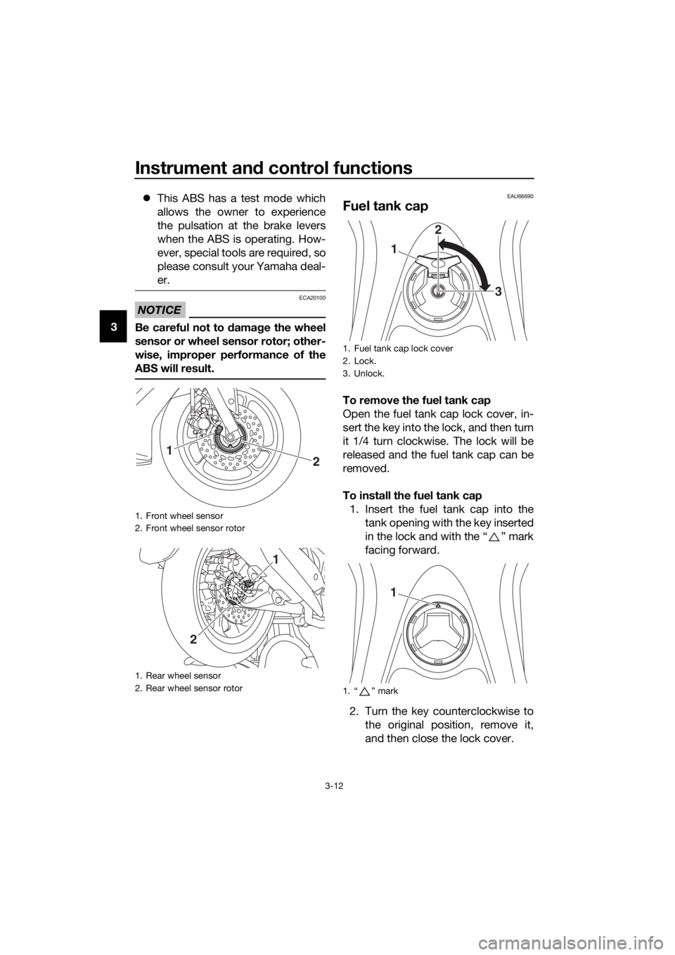
EAU66690
Fuel tank cap
To remove the fuel tank cap
Open the fuel tank cap lock cover, in-
sert the key into the lock, and then turn
it 1/4 turn clockwise. The lock will be
released and the fuel tank cap can be
removed.
To install the fuel tank cap 1. Insert the fuel tank cap into the tank opening with the key inserted
in the lock and with the “ ” mark
facing forward.
2. Turn the key counterclockwise to the original position, remove it,
and then close the lock cover.
1. Front wheel sensor
2. Front wheel sensor rotor
1. Rear wheel sensor
2. Rear wheel sensor rotor
2
1
1
2
1. Fuel tank cap lock cover
2. Lock.
3. Unlock.
1. “ ” mark
1 2
3
1
UBV3E0E0.book Page 12 Monday, September 26, 2016 3:42 PM
Page 30 of 94
Instrument and control functions
3-16
3
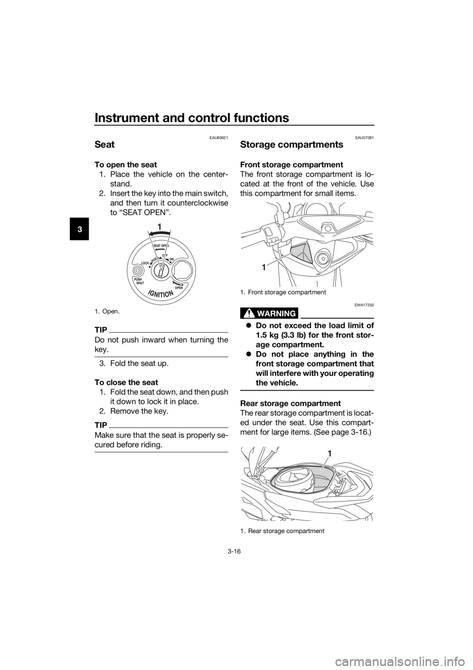
EAU60621
Seat
To open the seat
1. Place the vehicle on the center- stand.
2. Insert the key into the main switch, and then turn it counterclockwise
to “SEAT OPEN”.
TIP
Do not push inward when turning the
key.
3. Fold the seat up.
To close the seat 1. Fold the seat down, and then push it down to lock it in place.
2. Remove the key.
TIP
Make sure that the seat is properly se-
cured before riding.
EAU57081
Stora ge compartments
Front stora ge compartment
The front storage compartment is lo-
cated at the front of the vehicle. Use
this compartment for small items.
WARNING
EWA17250
Do not exceed the load limit of
1.5 k g (3.3 l b) for the front stor-
a g e compartment.
Do not place anythin g in the
front storag e compartment that
will interfere with your operatin g
the vehicle.
Rear stora ge compartment
The rear storage compartment is locat-
ed under the seat. Use this compart-
ment for large items. (See page 3-16.)
1. Open.
1
1. Front storage compartment
1. Rear storage compartment
1
1
UBV3E0E0.book Page 16 Monday, September 26, 2016 3:42 PM
Page 74 of 94
Periodic maintenance an d a djustment
6-34
6
EAU67290
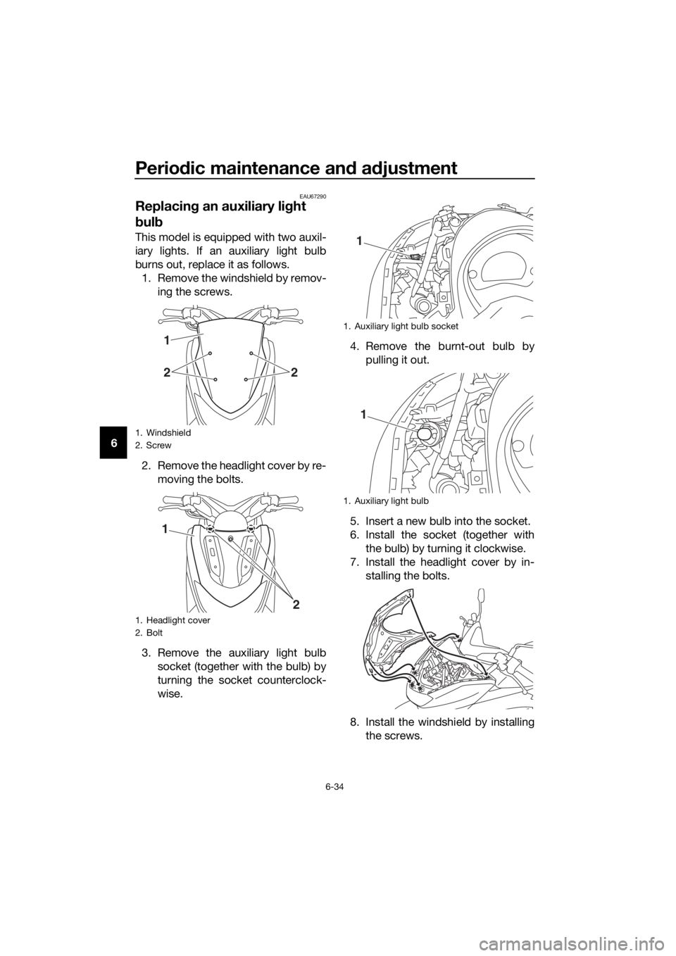
Replacin g an auxiliary lig ht
b ul b
This model is equipped with two auxil-
iary lights. If an auxiliary light bulb
burns out, replace it as follows.
1. Remove the windshield by remov- ing the screws.
2. Remove the headlight cover by re- moving the bolts.
3. Remove the auxiliary light bulb socket (together with the bulb) by
turning the socket counterclock-
wise. 4. Remove the burnt-out bulb by
pulling it out.
5. Insert a new bulb into the socket.
6. Install the socket (together with the bulb) by turning it clockwise.
7. Install the headlight cover by in- stalling the bolts.
8. Install the windshield by installing the screws.
1. Windshield
2. Screw
1. Headlight cover
2. Bolt
22
1
2
1
1. Auxiliary light bulb socket
1. Auxiliary light bulb
1
1
UBV3E0E0.book Page 34 Monday, September 26, 2016 3:42 PM
Page 76 of 94
Periodic maintenance an d a djustment
6-36
6
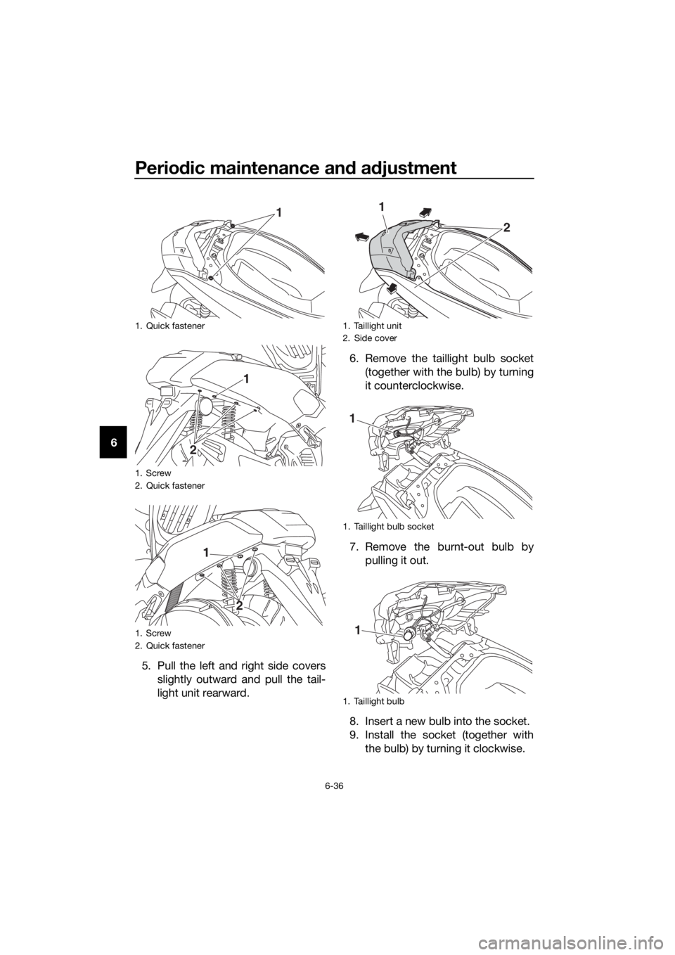
5. Pull the left and right side coversslightly outward and pull the tail-
light unit rearward. 6. Remove the taillight bulb socket
(together with the bulb) by turning
it counterclockwise.
7. Remove the burnt-out bulb by pulling it out.
8. Insert a new bulb into the socket.
9. Install the socket (together with the bulb) by turning it clockwise.
1. Quick fastener
1. Screw
2. Quick fastener
1. Screw
2. Quick fastener
1
2 1
1
2
1. Taillight unit
2. Side cover
1. Taillight bulb socket
1. Taillight bulb
1
2
1
1
UBV3E0E0.book Page 36 Monday, September 26, 2016 3:42 PM
Page 77 of 94
Periodic maintenance an d a djustment
6-37
6
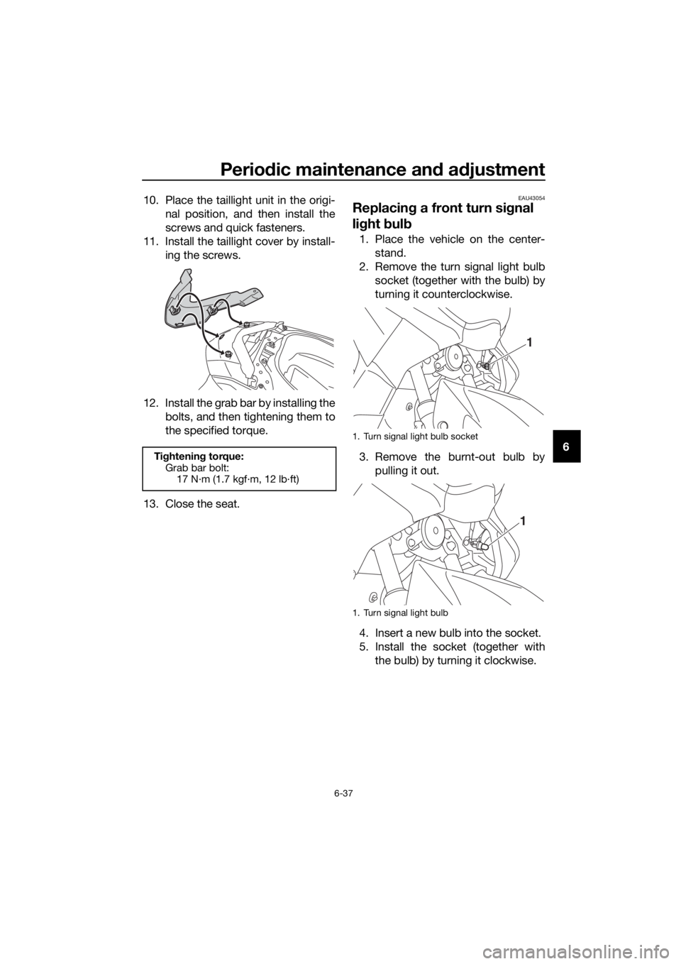
10. Place the taillight unit in the origi-
nal position, and then install the
screws and quick fasteners.
11. Install the taillight cover by install- ing the screws.
12. Install the grab bar by installing the bolts, and then tightening them to
the specified torque.
13. Close the seat.
EAU43054
Replacin g a front turn si gnal
lig ht bul b
1. Place the vehicle on the center-
stand.
2. Remove the turn signal light bulb socket (together with the bulb) by
turning it counterclockwise.
3. Remove the burnt-out bulb by pulling it out.
4. Insert a new bulb into the socket.
5. Install the socket (together with the bulb) by turning it clockwise.
Tightening torque:
Grab bar bolt: 17 N·m (1.7 kgf·m, 12 lb·ft)
1. Turn signal light bulb socket
1. Turn signal light bulb
1
1
UBV3E0E0.book Page 37 Monday, September 26, 2016 3:42 PM
Page 78 of 94
Periodic maintenance an d a djustment
6-38
6
EAU67320
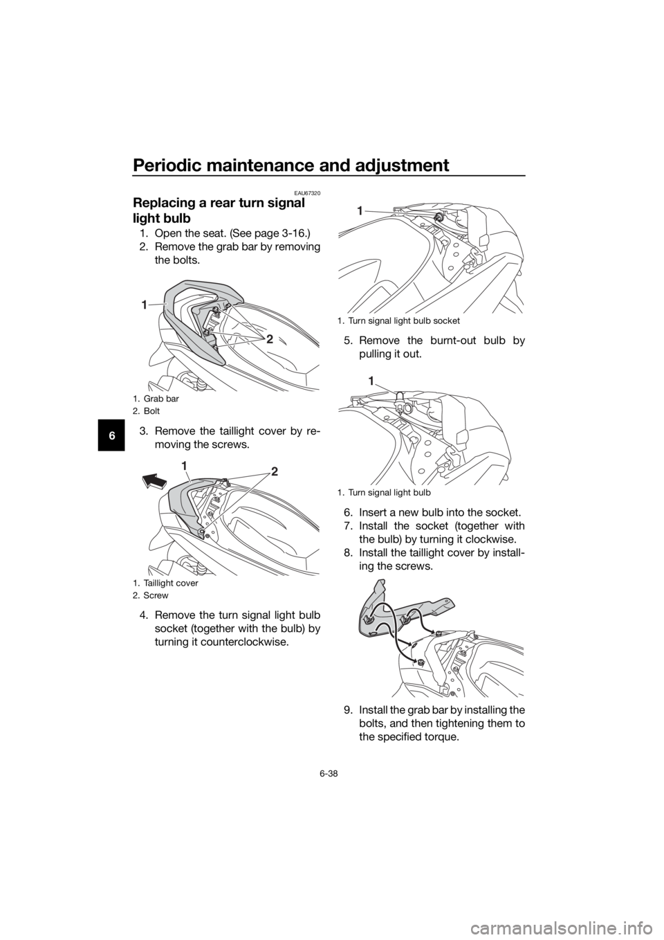
Replacin g a rear turn si gnal
li g ht bul b
1. Open the seat. (See page 3-16.)
2. Remove the grab bar by removing
the bolts.
3. Remove the taillight cover by re- moving the screws.
4. Remove the turn signal light bulb socket (together with the bulb) by
turning it counterclockwise. 5. Remove the burnt-out bulb by
pulling it out.
6. Insert a new bulb into the socket.
7. Install the socket (together with the bulb) by turning it clockwise.
8. Install the taillight cover by install- ing the screws.
9. Install the grab bar by installing the bolts, and then tightening them to
the specified torque.
1. Grab bar
2. Bolt
1. Taillight cover
2. Screw
1
2
12
1. Turn signal light bulb socket
1. Turn signal light bulb
1
1
UBV3E0E0.book Page 38 Monday, September 26, 2016 3:42 PM
Page 81 of 94
Periodic maintenance an d a djustment
6-41
6
En
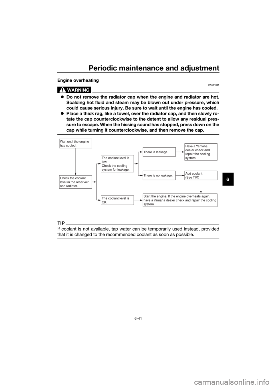
gine overheatin g
WARNING
EWAT1041
Do not remove the rad iator cap when the engine an d ra diator are hot.
Scal din g hot flui d an d steam may b e blown out un der pressure, which
coul d cause serious injury. Be sure to wait until the en gine has coole d.
Place a thick ra g, like a towel, over the rad iator cap, and then slowly ro-
tate the cap counterclockwise to the d etent to allow any residual pres-
sure to escape. When the hissin g soun d has stoppe d, press d own on the
cap while turnin g it counterclockwise, an d then remove the cap.
TIP
If coolant is not available, tap water can be temporarily used instead, provided
that it is changed to the recommended coolant as soon as possible.
Wait until the engine
has cooled.
Check the coolant
level in the reservoir
and radiator.Add coolant.
(See TIP.)
The coolant level is
OK.
There is no leakage.
There is leakage.
The coolant level is
low.
Check the cooling
system for leakage.
Have a Yamaha
dealer check and
repair the cooling
system.
Start the engine. If the engine overheats again,
have a Yamaha dealer check and repair the cooling
system.
UBV3E0E0.book Page 41 Monday, September 26, 2016 3:42 PM