warning YAMAHA NMAX 2015 Owner's Manual
[x] Cancel search | Manufacturer: YAMAHA, Model Year: 2015, Model line: NMAX, Model: YAMAHA NMAX 2015Pages: 90, PDF Size: 3.56 MB
Page 38 of 90
Operation and important rid ing points
5-2
5
EAU45093
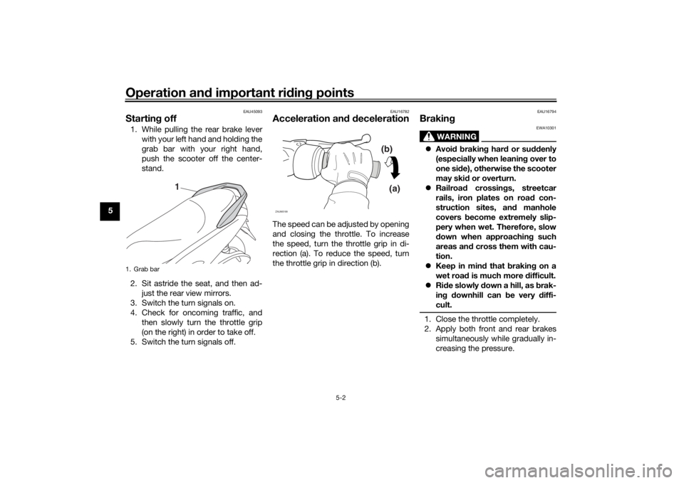
Startin g off1. While pulling the rear brake lever
with your left hand and holding the
grab bar with your right hand,
push the scooter off the center-
stand.
2. Sit astride the seat, and then ad- just the rear view mirrors.
3. Switch the turn signals on.
4. Check for oncoming traffic, and then slowly turn the throttle grip
(on the right) in order to take off.
5. Switch the turn signals off.
EAU16782
Acceleration an d d ecelerationThe speed can be adjusted by opening
and closing the throttle. To increase
the speed, turn the throttle grip in di-
rection (a). To reduce the speed, turn
the throttle grip in direction (b).
EAU16794
Brakin g
WARNING
EWA10301
Avoi d b rakin g har d or su ddenly
(especially when leanin g over to
one si de), otherwise the scooter
may skid or overturn.
Railroa d crossin gs, streetcar
rails, iron plates on roa d con-
struction sites, an d manhole
covers become extremely slip-
pery when wet. Therefore, slow
d own when approachin g such
areas an d cross them with cau-
tion.
Keep in min d that b raking on a
wet road is much more difficult.
Ride slowly d own a hill, as brak-
in g d ownhill can be very d iffi-
cult.1. Close the throttle completely.
2. Apply both front and rear brakes simultaneously while gradually in-
creasing the pressure.
1. Grab bar
1
(b)
(a)
ZAUM0199
U2DSE0E0.book Page 2 Thursday, March 19, 2015 10:34 AM
Page 40 of 90
Operation and important rid ing points
5-4
5
EAU17214
Parkin gWhen parking, stop the engine, and
then remove the key from the main
switch.
WARNING
EWA10312
Since the en gine an d exhaust
system can become very hot,
park in a place where pe destri-
ans or chil dren are not likely to
touch them and b e burne d.
Do not park on a slope or on soft
groun d, otherwise the vehicle
may overturn, increasin g the
risk of a fuel leak an d fire.
Do not park near g rass or other
flammab le materials which
mi ght catch fire.
U2DSE0E0.book Page 4 Thursday, March 19, 2015 10:34 AM
Page 41 of 90
Periodic maintenance an d a djustment
6-1
6
EAU17246
Periodic inspection, adjustment, and
lubrication will keep your vehicle in the
safest and most efficient condition
possible. Safety is an obligation of the
vehicle owner/operator. The most im-
portant points of vehicle inspection,
adjustment, and lubrication are ex-
plained on the following pages.
The intervals given in the periodic
maintenance charts should be simply
considered as a general guide under
normal riding conditions. However, de-
pending on the weather, terrain, geo-
graphical location, and individual use,
the maintenance intervals may need to
be shortened.
WARNING
EWA10322
Failure to properly maintain the vehi-
cle or performin g maintenance ac-
tivities incorrectly may increase
your risk of injury or death during
service or while usin g the vehicle. If
you are not familiar with vehicle ser-
vice, have a Yamaha d ealer perform
service.
WARNING
EWA15123
Turn off the en gine when performin g
maintenance unless otherwise
specified .
A runnin g en gine has movin g
parts that can catch on b ody
parts or clothin g an d electrical
parts that can cause shocks or
fires.
Runnin g the eng ine while ser-
vicin g can lead to eye injury,
b urns, fire, or car bon monoxi de
poisonin g – possi bly lea din g to
d eath. See pag e 1-3 for more in-
formation a bout car bon monox-
i d e.
WARNING
EWA15461
Brake discs, calipers, drums, an d
linin gs can b ecome very hot during
use. To avoi d possi ble burns, let
b rake components cool before
touching them.
EAU39692
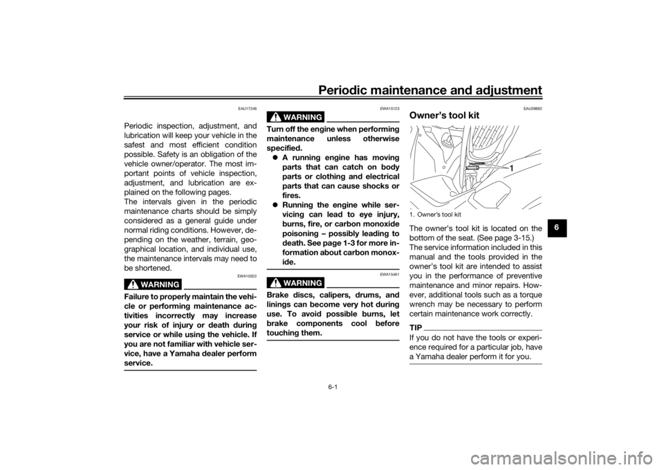
Owner’s tool kitThe owner’s tool kit is located on the
bottom of the seat. (See page 3-15.)
The service information included in this
manual and the tools provided in the
owner’s tool kit are intended to assist
you in the performance of preventive
maintenance and minor repairs. How-
ever, additional tools such as a torque
wrench may be necessary to perform
certain maintenance work correctly.TIPIf you do not have the tools or experi-
ence required for a particular job, have
a Yamaha dealer perform it for you.1. Owner’s tool kit
1
U2DSE0E0.book Page 1 Thursday, March 19, 2015 10:34 AM
Page 50 of 90
Periodic maintenance an d a djustment
6-10
6 4. Install the panels.
EAU66991
En
gine oil an d oil strainerThe engine oil level should be checked
before each ride. In addition, the oil
must be changed and the oil strainer
cleaned at the intervals specified in the
periodic maintenance and lubrication
chart.
To check the en gine oil level
1. Place the vehicle on the center- stand. A slight tilt to the side can
result in a false reading.
2. Start the engine, warm it up for several minutes, and then turn it
off.
3. Wait a few minutes until the oil set- tles, remove the engine oil filler
cap, wipe the engine oil dipstick
clean, insert it back into the oil fill-
er hole (without screwing it in), and
then remove it again to check the
oil level. WARNING! The muffler
an d muffler protector become
very hot d uring use. To avoi d
possi ble burns, let the muffler
an d protector cool before re-
movin g the oil filler cap.
[EWA17810]
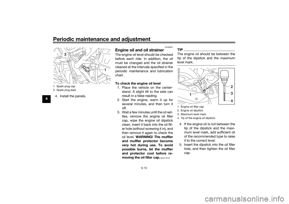
TIPThe engine oil should be between the
tip of the dipstick and the maximum
level mark.4. If the engine oil is not between the
tip of the dipstick and the maxi-
mum level mark, add sufficient oil
of the recommended type to raise
it to the correct level.
5. Insert the dipstick into the oil filler hole, and then tighten the oil filler
cap.
1. Spark plug cap
2. Spark plug lead
1
2
1. Engine oil filler cap
2. Engine oil dipstick
3. Maximum level mark
4. Tip of the engine oil dipstick
1
234
U2DSE0E0.book Page 10 Thursday, March 19, 2015 10:34 AM
Page 53 of 90
Periodic maintenance an d a djustment
6-13
6
6. Install the final transmission oil
drain bolt and its new gasket, and
then tighten the bolt to the speci-
fied torque.
7. Refill with the specified amount of the recommended final transmis-
sion oil. WARNING! Make sure
that no forei gn material enters
the final transmission case.
Make sure that no oil gets on
the tire or wheel.
[EWA11312]
8. Install the final transmission oil fill- er cap and its new O-ring, and
then tighten the oil filler cap.
9. Check the final transmission case for oil leakage. If oil is leaking,
check for the cause.
EAU20071
CoolantThe coolant level should be checked
before each ride. In addition, the cool-
ant must be changed at the intervals
specified in the periodic maintenance
and lubrication chart.
EAUN1090
To check the coolant level1. Place the vehicle on the center- stand.TIPThe coolant level must be
checked on a cold engine since
the level varies with engine tem-
perature.
Make sure that the vehicle is posi-
tioned straight up when checking
the coolant level. A slight tilt to the
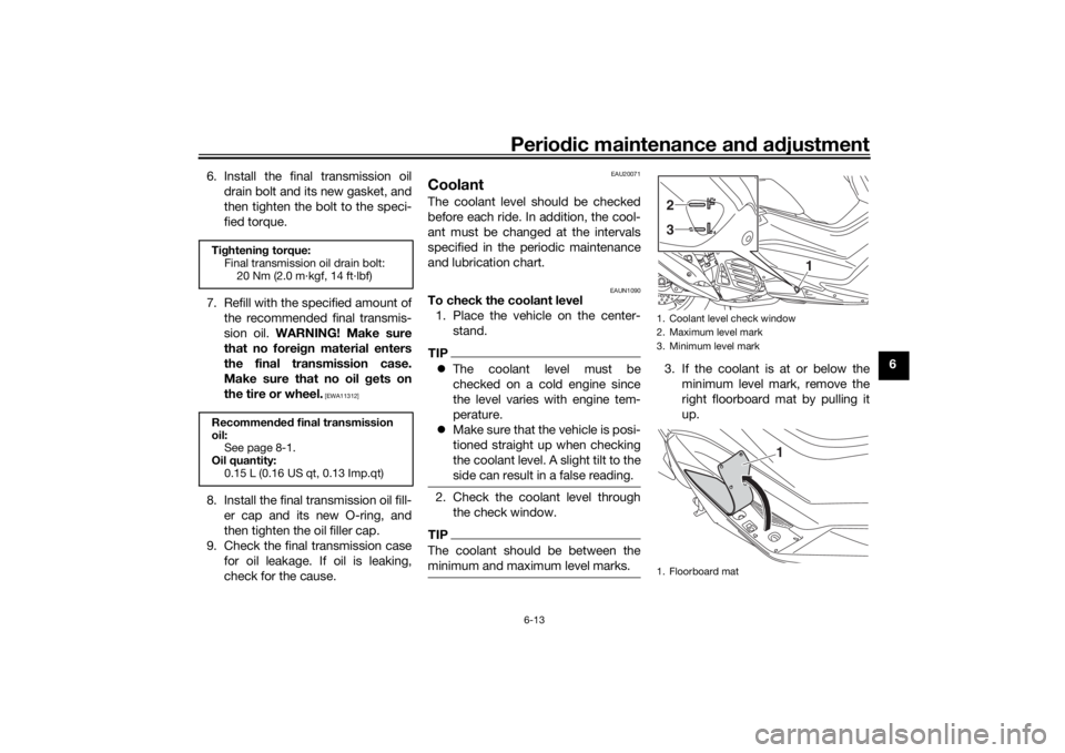
side can result in a false reading.2. Check the coolant level through
the check window.TIPThe coolant should be between the
minimum and maximum level marks.
3. If the coolant is at or below theminimum level mark, remove the
right floorboard mat by pulling it
up.
Tightenin g torque:
Final transmission oil drain bolt: 20 Nm (2.0 m·kgf, 14 ft·lbf)
Recommen ded final transmission
oil: See page 8-1.
Oil quantity: 0.15 L (0.16 US qt, 0.13 Imp.qt)
1. Coolant level check window
2. Maximum level mark
3. Minimum level mark
1. Floorboard mat
1
23
1
U2DSE0E0.book Page 13 Thursday, March 19, 2015 10:34 AM
Page 54 of 90
Periodic maintenance an d a djustment
6-14
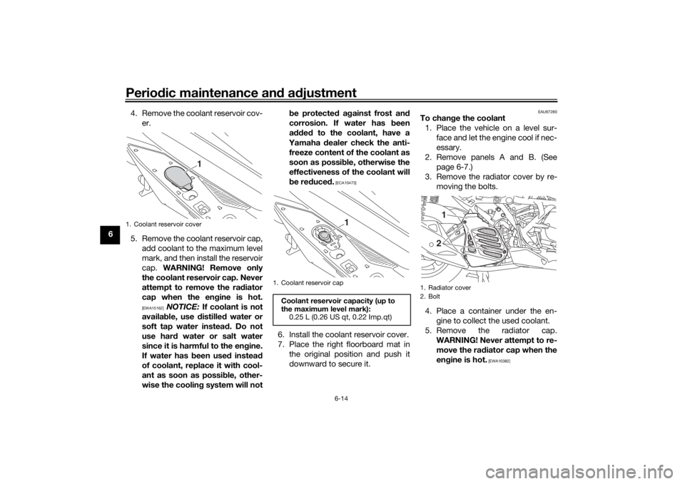
6 4. Remove the coolant reservoir cov-
er.
5. Remove the coolant reservoir cap, add coolant to the maximum level
mark, and then install the reservoir
cap. WARNING! Remove only
the coolant reservoir cap. Never
attempt to remove the ra diator
cap when the en gine is hot.
[EWA15162]
NOTICE: If coolant is not
availa ble, use distille d water or
soft tap water instea d. Do not
use har d water or salt water
since it is harmful to the en gine.
If water has been used instead
of coolant, replace it with cool-
ant as soon as possi ble, other-
wise the coolin g system will not b
e protecte d a gainst frost an d
corrosion. If water has been
a dde d to the coolant, have a
Yamaha dealer check the anti-
freeze content of the coolant as
soon as possi ble, otherwise the
effectiveness of the coolant will
b e re duce d.
[ECA10473]
6. Install the coolant reservoir cover.
7. Place the right floorboard mat in
the original position and push it
downward to secure it.
EAU67280
To chan ge the coolant
1. Place the vehicle on a level sur- face and let the engine cool if nec-
essary.
2. Remove panels A and B. (See page 6-7.)
3. Remove the radiator cover by re- moving the bolts.
4. Place a container under the en- gine to collect the used coolant.
5. Remove the radiator cap. WARNING! Never attempt to re-
move the ra diator cap when the
en gine is hot.
[EWA10382]
1. Coolant reservoir cover
1
1. Coolant reservoir capCoolant reservoir capacity (up to
the maximum level mark):
0.25 L (0.26 US qt, 0.22 Imp.qt)
1
1. Radiator cover
2. Bolt
1
2
U2DSE0E0.book Page 14 Thursday, March 19, 2015 10:34 AM
Page 57 of 90
![YAMAHA NMAX 2015 Owners Manual Periodic maintenance an d a djustment
6-17
6
b
e operated without the air filter
element installed , otherwise the
piston(s) an d/or cylin der(s) may
b ecome excessively worn.
[ECA10482]
5. Install t YAMAHA NMAX 2015 Owners Manual Periodic maintenance an d a djustment
6-17
6
b
e operated without the air filter
element installed , otherwise the
piston(s) an d/or cylin der(s) may
b ecome excessively worn.
[ECA10482]
5. Install t](/img/51/51058/w960_51058-56.png)
Periodic maintenance an d a djustment
6-17
6
b
e operated without the air filter
element installed , otherwise the
piston(s) an d/or cylin der(s) may
b ecome excessively worn.
[ECA10482]
5. Install the air filter case cover by
installing the screws.
Cleanin g the air filter check hose
1. Check the hose on the rear side of the air filter case for accumulated
dirt or water.
2. If dirt or water is visible, remove the hose from the clamp, clean it,
and then install it. Cleanin
g the V- belt case air filter el-
ement 1. Place the vehicle on the center- stand.
2. Remove the screws, and then pull the V-belt case air filter element
cover outward and away from the
V-belt case.
3. Pull the V-belt case air filter ele- ment out, and then clean it with
solvent. After cleaning, remove
the remaining solvent by squeez-
ing the element. WARNING! Use
only a ded icated parts cleanin g
solvent. To avoi d the risk of fire
or explosion, do not use gaso-
line or solvents with a low flash point.
[EWA10432]
NOTICE: To avoi d
d ama gin g the air filter element,
hand le it g ently an d carefully,
an d d o not twist it.
[ECA10522]
4. Apply oil of the recommended
type to the entire surface of the
sponge material, and then
squeeze the excess oil out.
1. Air filter check hose
1
1. V-belt case air filter element cover
2. Screw
2
2
1
1. V-belt case air filter element
1
U2DSE0E0.book Page 17 Thursday, March 19, 2015 10:34 AM
Page 59 of 90
Periodic maintenance an d a djustment
6-19
6
EAU21402
Valve clearanceThe valve clearance changes with use,
resulting in improper air-fuel mixture
and/or engine noise. To prevent this
from occurring, the valve clearance
must be adjusted by a Yamaha dealer
at the intervals specified in the periodic
maintenance and lubrication chart.
EAUN0701
TiresTires are the only contact between the
vehicle and the road. Safety in all con-
ditions of riding depends on a relatively
small area of road contact. Therefore, it
is essential to maintain the tires in good
condition at all times and replace them
at the appropriate time with the speci-
fied tires.
Tire air pressure
The tire air pressure should be
checked and, if necessary, adjusted
before each ride.
WARNING
EWA10504
Operation of this vehicle with im-
proper tire pressure may cause se-
vere injury or d eath from loss of
control. The tire air pressure must b e
checked and a djuste d on col d
tires (i.e., when the temperature
of the tires equals the am bient
temperature).
The tire air pressure must b e
a d juste d in accor dance with the
ri din g speed and with the total wei
ght of ri der, passen ger, car-
g o, an d accessories approve d
for this mo del.
WARNING
EWA10512
Never overloa d your vehicle. Opera-
tion of an overloa ded vehicle coul d
cause an acci dent.
Tire air pressure (measure d on col d
tires): Front (1 person):150 kPa (1.50 kgf/cm2, 22 psi)
Rear (1 person): 250 kPa (2.50 kgf/cm2, 36 psi)
Front (2 persons):
150 kPa (1.50 kgf/cm2, 22 psi)
Rear (2 persons): 250 kPa (2.50 kgf/cm2, 36 psi)
Maximum loa d*:
168 kg (370 lb)
* Total weight of rider, passenger, car-
go and accessories
U2DSE0E0.book Page 19 Thursday, March 19, 2015 10:34 AM
Page 60 of 90
Periodic maintenance an d a djustment
6-20
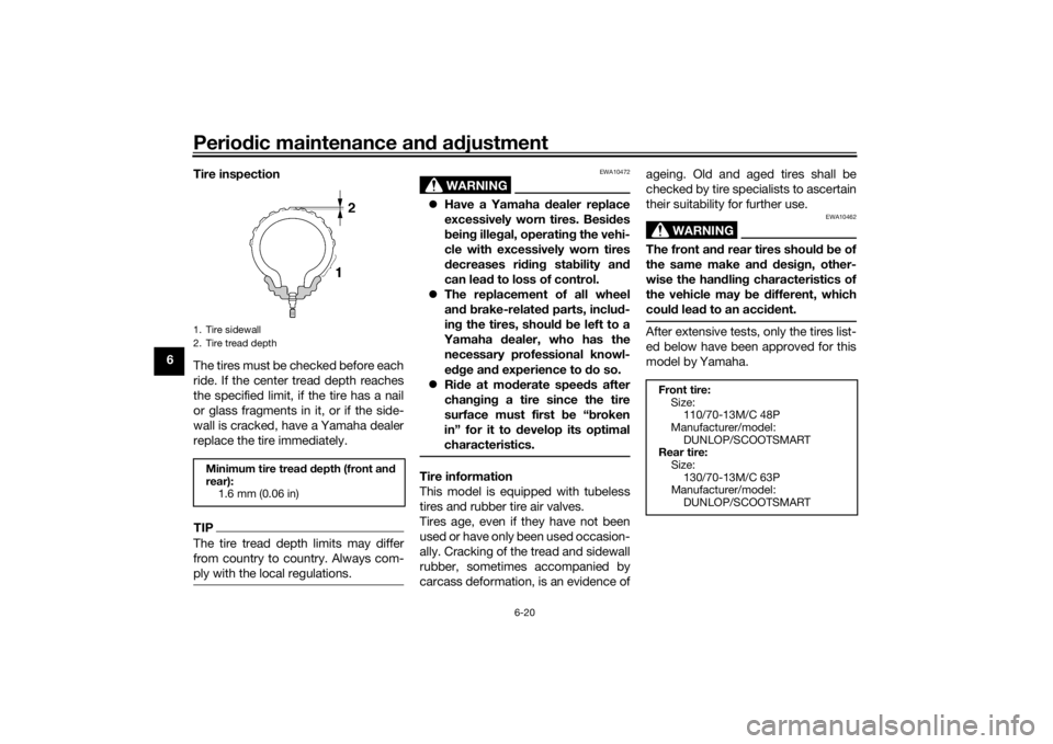
6 Tire inspection
The tires must be checked before each
ride. If the center tread depth reaches
the specified limit, if the tire has a nail
or glass fragments in it, or if the side-
wall is cracked, have a Yamaha dealer
replace the tire immediately.
TIPThe tire tread depth limits may differ
from country to country. Always com-
ply with the local regulations.
WARNING
EWA10472
Have a Yamaha dealer replace
excessively worn tires. Besi des
b ein g ille gal, operatin g the vehi-
cle with excessively worn tires
d ecreases ri din g sta bility an d
can lead to loss of control.
The replacement of all wheel
and b rake-relate d parts, inclu d-
in g the tires, shoul d b e left to a
Yamaha dealer, who has the
necessary professional knowl-
e dge an d experience to d o so.
Ride at mo derate speed s after
chan gin g a tire since the tire
surface must first be “ broken
in” for it to develop its optimal
characteristics.Tire information
This model is equipped with tubeless
tires and rubber tire air valves.
Tires age, even if they have not been
used or have only been used occasion-
ally. Cracking of the tread and sidewall
rubber, sometimes accompanied by
carcass deformation, is an evidence of ageing. Old and aged tires shall be
checked by tire specialists to ascertain
their suitability for further use.
WARNING
EWA10462
The front an
d rear tires shoul d b e of
the same make an d d esi gn, other-
wise the han dlin g characteristics of
the vehicle may b e different, which
coul d lea d to an acci dent.After extensive tests, only the tires list-
ed below have been approved for this
model by Yamaha.
1. Tire sidewall
2. Tire tread depthMinimum tire trea d d epth (front an d
rear): 1.6 mm (0.06 in)
Front tire:Size:110/70-13M/C 48P
Manufacturer/model: DUNLOP/SCOOTSMART
Rear tire:
Size:130/70-13M/C 63P
Manufacturer/model:
DUNLOP/SCOOTSMART
U2DSE0E0.book Page 20 Thursday, March 19, 2015 10:34 AM
Page 61 of 90
Periodic maintenance an d a djustment
6-21
6
EAU21963
Cast wheelsTo maximize the performance, durabil-
ity, and safe operation of your vehicle,
note the following points regarding the
specified wheels.
The wheel rims should be
checked for cracks, bends, warp-
age or other damage before each
ride. If any damage is found, have
a Yamaha dealer replace the
wheel. Do not attempt even the
smallest repair to the wheel. A de-
formed or cracked wheel must be
replaced.
The wheel should be balanced
whenever either the tire or wheel
has been changed or replaced. An
unbalanced wheel can result in
poor performance, adverse han-
dling characteristics, and a short-
ened tire life.
EAU50861
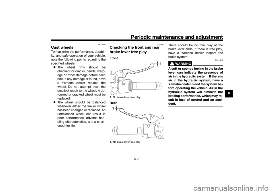
Checkin g the front an d rear
b rake lever free playFront
Rear There should be no free play at the
brake lever ends. If there is free play,
have a Yamaha dealer inspect the
brake system.
WARNING
EWA14212
A soft or spon
gy feelin g in the b rake
lever can in dicate the presence of
air in the hy draulic system. If there is
air in the hy draulic system, have a
Yamaha dealer blee d the system be-
fore operatin g the vehicle. Air in the
hy draulic system will diminish the
b rakin g performance, which may re-
sult in loss of control an d an acci-
d ent.
1. No brake lever free play
1. No brake lever free play
1
1
U2DSE0E0.book Page 21 Thursday, March 19, 2015 10:34 AM