check engine YAMAHA PW50 2016 User Guide
[x] Cancel search | Manufacturer: YAMAHA, Model Year: 2016, Model line: PW50, Model: YAMAHA PW50 2016Pages: 80, PDF Size: 1.84 MB
Page 53 of 80

Periodic maintenance an d a djustment
7-12
7
EAU39931
A djustin g the car buretor
The carburetor is an important part of
the engine and requires very sophisti-
cated adjustment. Therefore, most
carburetor adjustments should be left
to a Yamaha dealer, who has the nec-
essary professional knowledge and ex-
perience. The adjustment described in
the following section, however, may be
serviced by the owner as part of rou-
tine maintenance.
NOTICE
ECA10551
The car buretor has been set an d ex-
tensively teste d at the Yamaha fac-
tory. Chan gin g these settin gs
without sufficient technical knowl-
e dge may result in poor perfor-
mance of or damag e to the en gine.
EAU21363
A djustin g the en gine i dlin g
spee d
The engine idling speed must be
checked and, if necessary, adjusted as
follows at the intervals specified in the
periodic maintenance and lubrication
chart.
TIP
A diagnostic tachometer is needed to
make this adjustment.
1. Attach the tachometer to the
spark plug lead.
2. Start the engine and warm it up for several minutes at 1000–2000
r/min while occasionally revving it
to 4000–5000 r/min.
TIP
The engine is warm when it quickly re-
sponds to the throttle.
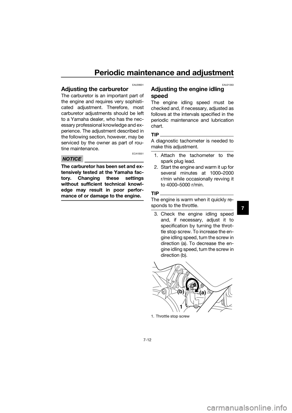
3. Check the engine idling speedand, if necessary, adjust it to
specification by turning the throt-
tle stop screw. To increase the en-
gine idling speed, turn the screw in
direction (a). To decrease the en-
gine idling speed, turn the screw in
direction (b).
1. Throttle stop screw
1 (a)
(b)
U2SA82E0.book Page 12 Monday, June 8, 2015 1:09 PM
Page 60 of 80

Periodic maintenance an d a djustment
7-19
7
EAU23115
Checkin g an d lu bricatin g the
throttle grip an d ca ble
The operation of the throttle grip
should be checked before each ride. In
addition, the cable should be lubricat-
ed by a Yamaha dealer at the intervals
specified in the periodic maintenance
chart.
The throttle cable is equipped with a
rubber cover. Make sure that the cover
is securely installed. Even though the
cover is installed correctly, it does not
completely protect the cable from wa-
ter entry. Therefore, use care not to
pour water directly onto the cover or
cable when washing the vehicle. If the
cable or cover becomes dirty, wipe
clean with a moist cloth.
EAU23121
A djustin g the Autolu be pump
The Autolube pump is a vital and so-
phisticated component of the engine,
which must be adjusted by a Yamaha
dealer at the intervals specified in the
periodic maintenance and lubrication
chart.
U2SA82E0.book Page 19 Monday, June 8, 2015 1:09 PM
Page 68 of 80

Periodic maintenance an d a djustment
7-27
7
EAU68120
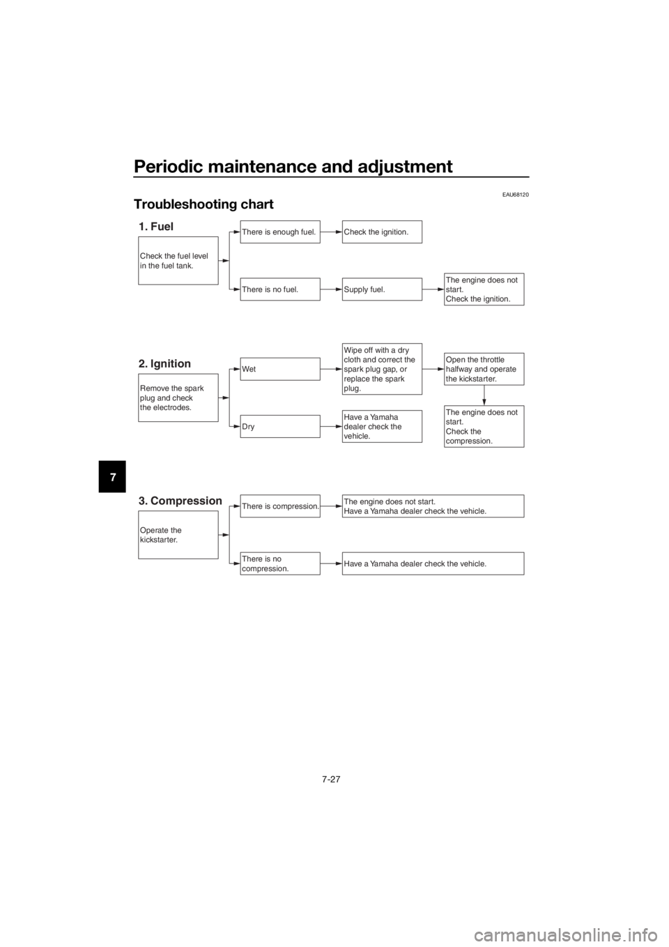
Trou bleshootin g chart
1. FuelThere is enough fuel.
There is no fuel.
Check the ignition.
Supply fuel.The engine does not
start.
Check the ignition.
Open the throttle
halfway and operate
the kickstarter.Wipe off with a dry
cloth and correct the
spark plug gap, or
replace the spark
plug.
2. IgnitionWet
Dry
There is compression.
There is no
compression.
The engine does not start.
Have a Yamaha dealer check the vehicle.
Have a Yamaha dealer check the vehicle.
The engine does not
start.
Check the
compression.Have a Yamaha
dealer check the
vehicle.
Remove the spark
plug and check
the electrodes.
Operate the
kickstarter.
Check the fuel level
in the fuel tank.
3. Compression
U2SA82E0.book Page 27 Monday, June 8, 2015 1:09 PM
Page 72 of 80

Motorcycle care and stora ge
8-4
8 5. Perform the following steps to
protect the cylinder, piston rings,
etc. from corrosion.a. Remove the spark plug cap and spark plug.
b. Pour a teaspoonful of engine oil into the spark plug bore.
c. Install the spark plug cap onto the spark plug, and then place
the spark plug on the cylinder
head so that the electrodes are
grounded. (This will limit spark-
ing during the next step.)
d. Turn the engine over several times with the starter. (This will
coat the cylinder wall with oil.)
e. Remove the spark plug cap from the spark plug, and then
install the spark plug and the
spark plug cap. WARNING! To
prevent damag e or injury
from sparkin g, make sure to
g roun d the spark plu g elec-
tro des while turnin g the en-
g ine over. [EWA10952]
6. Lubricate all control cables and
the pivoting points of all levers as
well as of the centerstand.
7. Check and, if necessary, correct the tire air pressure, and then lift
the motorcycle so that both of its
wheels are off the ground. Alterna-
tively, turn the wheels a little every
month in order to prevent the tires
from becoming degraded in one
spot.
8. Cover the muffler outlet with a plastic bag to prevent moisture
from entering it.
TIP
Make any necessary repairs before
storing the motorcycle.
U2SA82E0.book Page 4 Monday, June 8, 2015 1:09 PM
Page 78 of 80

11-1
11
Index
A
Acceleration and deceleration ................ 6-3
Air filter element, cleaning .................... 7-10
Autolube pump, adjusting..................... 7-19
B
Brake lever, front .................................... 4-2
Brake lever, rear...................................... 4-3
Brake levers, lubricating ....................... 7-20
Brake shoes, checking ......................... 7-17
Braking.................................................... 6-3
C
Cable lock (for Europe) ........................... 4-9
Cables, checking and lubricating ......... 7-18
Carburetor, adjusting ............................ 7-12
Care ........................................................ 8-1
Centerstand, checking and
lubricating ........................................... 7-20
E
Engine break-in....................................... 6-4
Engine idling speed .............................. 7-12
Engine oil ................................................ 4-6
Engine serial number ............................ 10-1
Engine, starting a warm .......................... 6-2
Engine stop switch ................................. 4-1
F
Front and rear brake lever free play, adjusting ............................................. 7-16
Front fork, checking .............................. 7-21
Fuel ......................................................... 4-4
Fuel cock ................................................ 4-7
Fuel tank breather hose .......................... 4-6
Fuel tank cap .......................................... 4-3
H
Handlebar switch .................................... 4-1
I
Identification numbers .......................... 10-1
K
Kickstarter............................................... 4-8
L
Labels, location....................................... 1-1
M
Maintenance and lubrication, periodic ... 7-4
Maintenance, emission control system .................................................. 7-3
Matte color, caution ................................ 8-1
Middle and final gear cases .................... 7-9
Model label ........................................... 10-1
P
Parking .................................................... 6-4
Part locations .......................................... 3-1 Power reduction plate, removing ........... 7-7
S
Safety information .................................. 2-1
Seat ........................................................ 4-8
Spark arrester, cleaning ....................... 7-11
Spark plug, checking ............................. 7-6
Specifications ......................................... 9-1
Speed limiter and power reduction
plate ..................................................... 4-1
Starter (choke) lever ............................... 4-7
Starting and warming up a cold engine .................................................. 6-1
Starting off.............................................. 6-2
Steering, checking................................ 7-21
Storage ................................................... 8-3
T
Throttle grip and cable, checking and
lubricating .......................................... 7-19
Throttle grip free play, checking........... 7-13
Tires ...................................................... 7-14
Tool kit.................................................... 7-2
Transmission oil ..................................... 7-8
Troubleshooting ................................... 7-26
Troubleshooting chart .......................... 7-27
V
Vehicle Emission Control Information label (For Canada) .............................. 10-2
Vehicle identification number ............... 10-1
W
Wheel bearings, checking .................... 7-22
Wheel (front) ......................................... 7-22
Wheel (rear) .......................................... 7-24
Wheels .................................................. 7-16
U2SA82E0.book Page 1 Monday, June 8, 2015 1:09 PM