air filter YAMAHA PW50 2016 Owners Manual
[x] Cancel search | Manufacturer: YAMAHA, Model Year: 2016, Model line: PW50, Model: YAMAHA PW50 2016Pages: 80, PDF Size: 1.84 MB
Page 8 of 80

Table of contents
Location of important la bels ........... 1-1
Safety information ............................ 2-1
Description ....................................... 3-1
Left view ......................................... 3-1
Right view ....................................... 3-2
Controls and instruments ............... 3-3
Instrument an d control functions ... 4-1
Handlebar switch............................ 4-1
Speed limiter and power reduction
plate ............................................ 4-1
Front brake lever ............................ 4-2
Rear brake lever ............................. 4-3
Fuel tank cap .................................. 4-3
Fuel ................................................. 4-4
Fuel tank breather hose.................. 4-6
2-stroke engine oil .......................... 4-6
Fuel cock ........................................ 4-7
Starter (choke) lever ...................... 4-7
Kickstarter ...................................... 4-8
Seat ................................................ 4-8
Cable lock (for Europe) ................... 4-9
For your safety – pre-operation
checks ............................................... 5-1
Operation an d important ri din g
points ................................................ 6-1
Starting and warming up a cold engine ......................................... 6-1
Starting a warm engine .................. 6-2
Starting off ...................................... 6-2
Acceleration and deceleration ........ 6-3
Braking ........................................... 6-3
Engine break-in .............................. 6-4
Parking ........................................... 6-4
Perio dic maintenance an d
a d justment ........................................ 7-1
Owner’s tool kit .............................. 7-2
Periodic maintenance chart for the emission control system ............. 7-3
General maintenance and
lubrication chart .......................... 7-4 Checking the spark plug ................. 7-6
Removing the power reduction
plate ............................................. 7-7
Transmission oil .............................. 7-8
Middle and final gear cases ............ 7-9
Cleaning the air filter element ....... 7-10
Cleaning the spark arrester ........... 7-11
Adjusting the carburetor ............... 7-12
Adjusting the engine idling speed ......................................... 7-12
Checking the throttle grip free
play ............................................ 7-13
Tires .............................................. 7-14
Panel wheels ................................. 7-16
Adjusting the front and rear brake lever free play ............................ 7-16
Checking the front and rear brake
shoes ......................................... 7-17
Checking and lubricating the cables ........................................ 7-18
Checking and lubricating the throttle grip and cable ............... 7-19
Adjusting the Autolube pump ....... 7-19
Lubricating the front and rear
brake levers ............................... 7-20
Checking and lubricating the
centerstand ................................ 7-20
Checking the front fork ................. 7-21
Checking the steering ................... 7-21
Checking the wheel bearings ........ 7-22
Front wheel ................................... 7-22
Rear wheel .................................... 7-24
Troubleshooting ............................ 7-26
Troubleshooting chart ................... 7-27
Motorcycle care an d stora ge .......... 8-1
Matte color caution ......................... 8-1
Care................................................. 8-1
Storage............................................ 8-3
Specifications ................................... 9-1
Consumer information ................... 10-1
Identification numbers .................. 10-1
In dex .
............................................... 11-1
U2SA82E0.book Page 1 Monday, June 8, 2015 1:09 PM
Page 23 of 80

Description
3-1
3
EAU63371
Left view
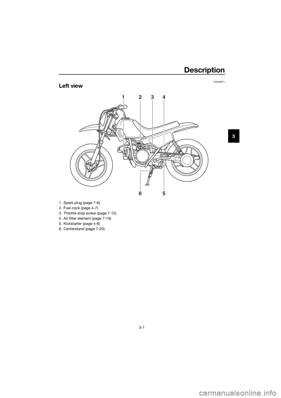
1234
56
1. Spark plug (page 7-6)
2. Fuel cock (page 4-7)
3. Throttle stop screw (page 7-12)
4. Air filter element (page 7-10)
5. Kickstarter (page 4-8)
6. Centerstand (page 7-20)
U2SA82E0.book Page 1 Monday, June 8, 2015 1:09 PM
Page 32 of 80

Instrument and control functions
4-7
4
EAU40702
Fuel cock
The fuel cock supplies fuel from the
tank to the carburetor while filtering it
also.
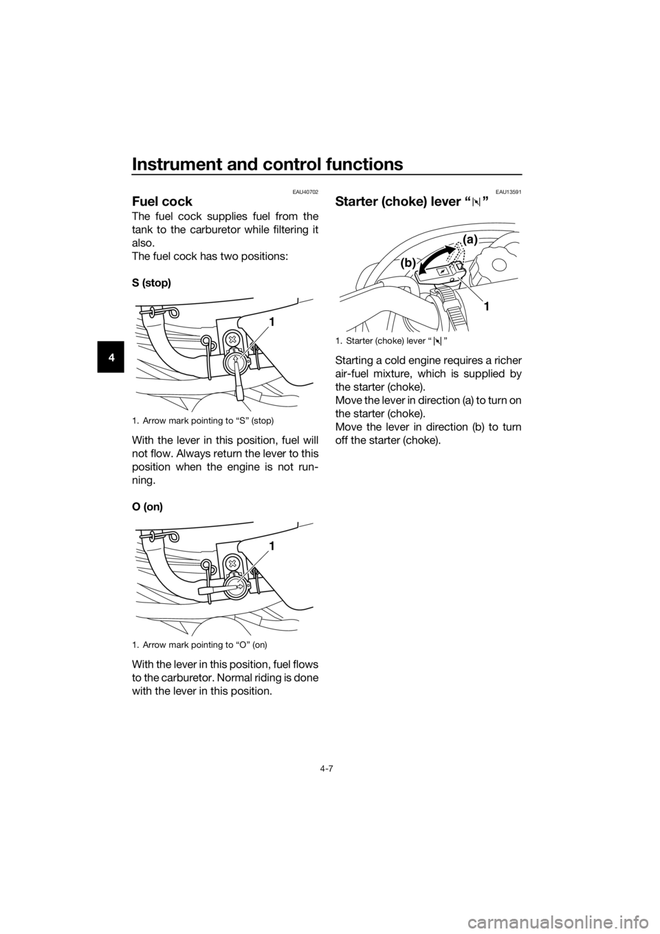
The fuel cock has two positions:
S (stop)
With the lever in this position, fuel will
not flow. Always return the lever to this
position when the engine is not run-
ning.
O (on)
With the lever in this position, fuel flows
to the carburetor. Normal riding is done
with the lever in this position.
EAU13591
Starter (choke) lever “ ”
Starting a cold engine requires a richer
air-fuel mixture, which is supplied by
the starter (choke).
Move the lever in direction (a) to turn on
the starter (choke).
Move the lever in direction (b) to turn
off the starter (choke).
1. Arrow mark pointing to “S” (stop)
1. Arrow mark pointing to “O” (on)
1
1
1. Starter (choke) lever “ ”
1
(a)
(b)
U2SA82E0.book Page 7 Monday, June 8, 2015 1:09 PM
Page 44 of 80

Periodic maintenance an d a djustment
7-3
7
EAU69180
Perio dic maintenance chart for the emission control system
TIP
Items marked with an asterisk should be performed by a Yamaha dealer as they
require special tools, data and technical skills.
4 *Carburetor Check engine idling speed and
starter operation.
Adjust if necessary.
Clean.
5 *Cylinder head and
exhaust system Check for leakage.
√
Tighten if necessary.
Decarbonize if necessary.
6
*Spark arrester Clean.√
NO. ITEM CHECK OR MAINTENANCE JOB
1 month3 months
6 months
6 months12 months
1
*Fuel line Check fuel hoses for cracks or
damage.√√√ √
√√√ √
√√
√
√
√√
√
√
√√
√ Replace if necessary.
2Spark plug Check condition.
Adjust gap and clean.
Replace if necessary.
3Air filter element
Clean with solvent.
Replace if necessary.
THEREAFTER
EVERYINITIAL
U2SA82E0.book Page 3 Monday, June 8, 2015 1:09 PM
Page 46 of 80

Periodic maintenance an d a djustment
7-5
7TIP
The air filter needs more frequent service if you are riding in unusually wet or dusty
areas.
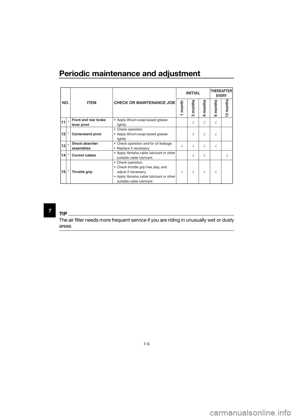
11 *Front and rear brake
lever pivot Apply lithium-soap-based grease
lightly.
12 *Centerstand pivot Check operation.
13
*Shock absorber
assemblies Check operation and for oil leakage.
14
*Control cables Apply Yamaha cable lubricant or other
suitable cable lubricant.
15 *Throttle grip Check operation.
Check throttle grip free play, and
adjust if necessary.
Apply Yamaha cable lubricant or other suitable cable lubricant.
Replace if necessary. Apply lithium-soap-based grease
lightly.
NO. ITEM CHECK OR MAINTENANCE JOB
1 month3 months
6 months
6 months12 months
√√√ √
√√√ √√√
√
√√
√
√
√√
THEREAFTER
EVERYINITIAL
U2SA82E0.book Page 5 Monday, June 8, 2015 1:09 PM
Page 51 of 80

Periodic maintenance an d a djustment
7-10
7
EAU40904
Cleanin g the air filter element
The air filter element should be cleaned
at the intervals specified in the periodic
maintenance and lubrication chart.
Clean or, if necessary, replace the air
filter element more frequently if you are
riding in unusually wet or dusty areas.
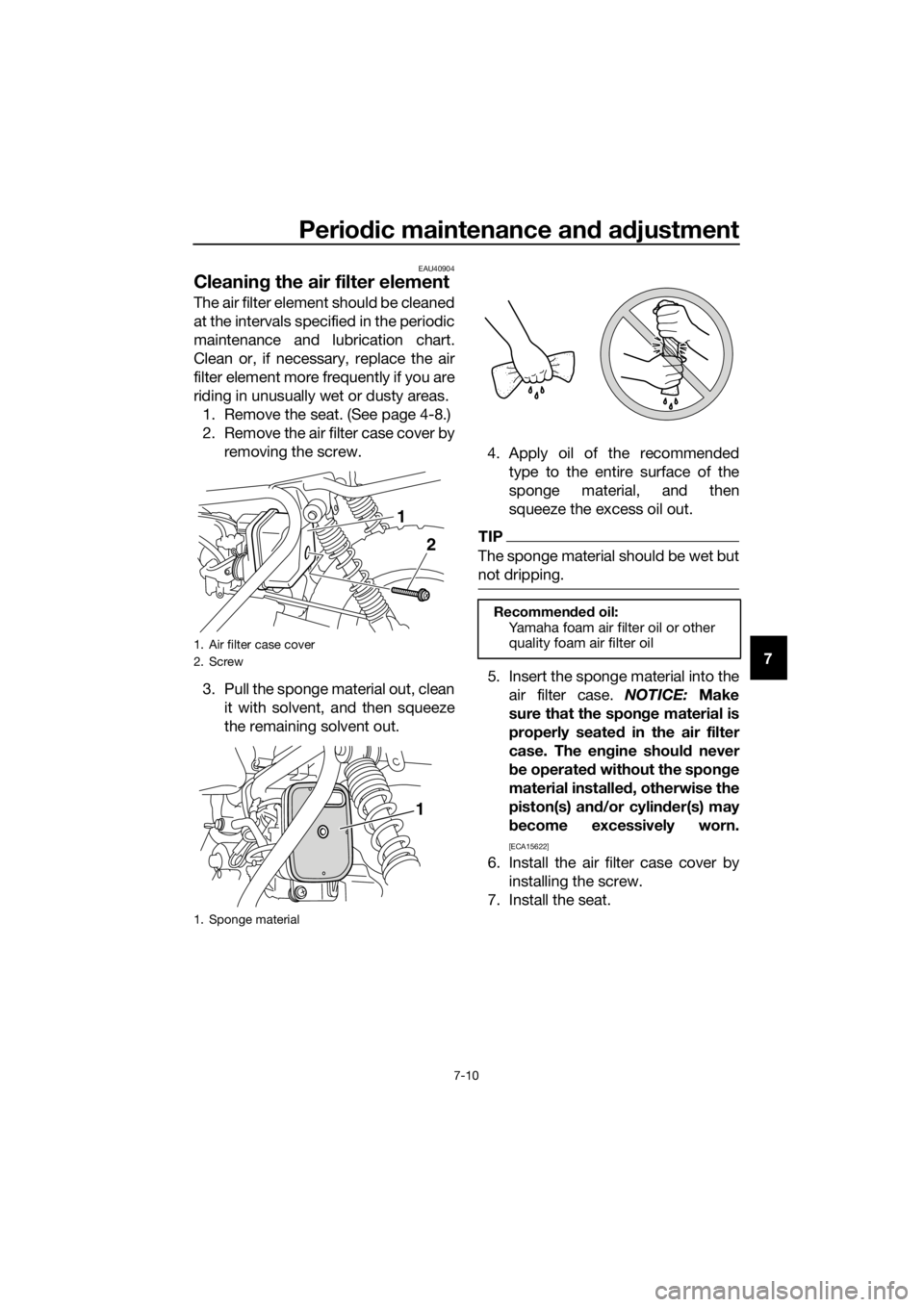
1. Remove the seat. (See page 4-8.)
2. Remove the air filter case cover by removing the screw.
3. Pull the sponge material out, clean it with solvent, and then squeeze
the remaining solvent out. 4. Apply oil of the recommended
type to the entire surface of the
sponge material, and then
squeeze the excess oil out.
TIP
The sponge material should be wet but
not dripping.
5. Insert the sponge material into theair filter case. NOTICE: Make
sure that the spon ge material is
properly seated in the air filter
case. The en gine shoul d never
b e operated without the spon ge
material installe d, otherwise the
piston(s) an d/or cylin der(s) may
b ecome excessively worn.
[ECA15622]
6. Install the air filter case cover by
installing the screw.
7. Install the seat.
1. Air filter case cover
2. Screw
1. Sponge material
2
1
1
Recommen
ded oil:
Yamaha foam air filter oil or other
quality foam air filter oil
U2SA82E0.book Page 10 Monday, June 8, 2015 1:09 PM
Page 73 of 80

Specifications
9-1
9
Dimensions:
Overall length:1245 mm (49.0 in)
Overall width:
575 mm (22.6 in)
Overall height: 715 mm (28.1 in)
Seat height: 485 mm (19.1 in)
Wheelbase:
855 mm (33.7 in)
Ground clearance: 105 mm (4.13 in)
Minimum turning radius: 1.3 m (4.27 ft)
Wei ght:
Curb weight:
39 kg (86 lb)
Technical permissible mass (Maximum load +
Curb weight):
64 kg (141 lb)
Noise an d vi bration level:
Noise level (77/311/EEC):
75.1 dB(A) at 2750 r/min
(PW50_AUT/BEL/CHE/CYP/CZE/DEU/DN
K/ESP/FIN/FRA/GBR/GRC/IRL/ITA/NLD/
NOR/POL/PRT/SVK/SVN/SWE)
Uncertainty of measurement:
3.0 dB(A)
(PW50_AUT/BEL/CHE/CYP/CZE/DEU/DN
K/ESP/FIN/FRA/GBR/GRC/IRL/ITA/NLD/
NOR/POL/PRT/SVK/SVN/SWE)
Vibration on seat (EN1032, ISO5008): Will not exceed 0.5 m/s²
(PW50_AUT/BEL/CHE/CYP/CZE/DEU/DN
K/ESP/FIN/FRA/GBR/GRC/IRL/ITA/NLD/
NOR/POL/PRT/SVK/SVN/SWE)
Vibration on handlebar (EN1032, ISO5008): Will not exceed 2.5 m/s²
(PW50_AUT/BEL/CHE/CYP/CZE/DEU/DN
K/ESP/FIN/FRA/GBR/GRC/IRL/ITA/NLD/
NOR/POL/PRT/SVK/SVN/SWE)
Engine:
Combustion cycle:
2-stroke
Cooling system: Air cooled
Number of cylinders:
Single cylinder Displacement:
49 cm³
Bore × stroke:
40.0 × 39.2 mm (1.57 × 1.54 in)
Compression ratio:
6.0 : 1
Starting system: Kickstarter
Lubrication system: Separate lubrication
Engine oil:
Engine oil:
YAMALUBE 2S or 2-stroke engine oil
(JASO FC grade or ISO EG-C [or EG-D]
grade)
Recommended brand: YAMALUBE
Engine oil quantity:
Engine oil tank capacity:0.30 L (0.32 US qt, 0.26 Imp.qt)
Transmission oil:
Type: Motor oil SAE 10W-30 type SE or higher or
Gear oil SAE 85W GL-3
Quantity: 0.30 L (0.32 US qt, 0.26 Imp.qt)
Air filter:
Air filter element:
Wet element
Fuel:
Recommended fuel:Regular unleaded gasoline only
Fuel tank capacity:
2.0 L (0.5 US gal, 0.4 Imp.gal)
Car buretor:
Type × quantity:
VM12SC × 1
Spark plu g(s):
Manufacturer/model:
NGK/BP4HS (PW50_ZAF)
NGK/BPR4HS
(PW50_AUT/BEL/CHE/CYP/CZE/DEU/DN
K/ESP/FIN/FRA/GBR/GRC/IRL/ITA/NLD/
NOR/POL/PRT/SVK/SVN/SWE/TUR,
PW50G, PW50G2)
Manufacturer/model:
DENSO/W14FP-L (PW50_ZAF)
Spark plug gap: 0.6–0.7 mm (0.024–0.028 in)
U2SA82E0.book Page 1 Monday, June 8, 2015 1:09 PM
Page 78 of 80

11-1
11
Index
A
Acceleration and deceleration ................ 6-3
Air filter element, cleaning .................... 7-10
Autolube pump, adjusting..................... 7-19
B
Brake lever, front .................................... 4-2
Brake lever, rear...................................... 4-3
Brake levers, lubricating ....................... 7-20
Brake shoes, checking ......................... 7-17
Braking.................................................... 6-3
C
Cable lock (for Europe) ........................... 4-9
Cables, checking and lubricating ......... 7-18
Carburetor, adjusting ............................ 7-12
Care ........................................................ 8-1
Centerstand, checking and
lubricating ........................................... 7-20
E
Engine break-in....................................... 6-4
Engine idling speed .............................. 7-12
Engine oil ................................................ 4-6
Engine serial number ............................ 10-1
Engine, starting a warm .......................... 6-2
Engine stop switch ................................. 4-1
F
Front and rear brake lever free play, adjusting ............................................. 7-16
Front fork, checking .............................. 7-21
Fuel ......................................................... 4-4
Fuel cock ................................................ 4-7
Fuel tank breather hose .......................... 4-6
Fuel tank cap .......................................... 4-3
H
Handlebar switch .................................... 4-1
I
Identification numbers .......................... 10-1
K
Kickstarter............................................... 4-8
L
Labels, location....................................... 1-1
M
Maintenance and lubrication, periodic ... 7-4
Maintenance, emission control system .................................................. 7-3
Matte color, caution ................................ 8-1
Middle and final gear cases .................... 7-9
Model label ........................................... 10-1
P
Parking .................................................... 6-4
Part locations .......................................... 3-1 Power reduction plate, removing ........... 7-7
S
Safety information .................................. 2-1
Seat ........................................................ 4-8
Spark arrester, cleaning ....................... 7-11
Spark plug, checking ............................. 7-6
Specifications ......................................... 9-1
Speed limiter and power reduction
plate ..................................................... 4-1
Starter (choke) lever ............................... 4-7
Starting and warming up a cold engine .................................................. 6-1
Starting off.............................................. 6-2
Steering, checking................................ 7-21
Storage ................................................... 8-3
T
Throttle grip and cable, checking and
lubricating .......................................... 7-19
Throttle grip free play, checking........... 7-13
Tires ...................................................... 7-14
Tool kit.................................................... 7-2
Transmission oil ..................................... 7-8
Troubleshooting ................................... 7-26
Troubleshooting chart .......................... 7-27
V
Vehicle Emission Control Information label (For Canada) .............................. 10-2
Vehicle identification number ............... 10-1
W
Wheel bearings, checking .................... 7-22
Wheel (front) ......................................... 7-22
Wheel (rear) .......................................... 7-24
Wheels .................................................. 7-16
U2SA82E0.book Page 1 Monday, June 8, 2015 1:09 PM