wheel bolts YAMAHA PW50 2016 Owners Manual
[x] Cancel search | Manufacturer: YAMAHA, Model Year: 2016, Model line: PW50, Model: YAMAHA PW50 2016Pages: 80, PDF Size: 1.84 MB
Page 65 of 80

Periodic maintenance an d a djustment
7-24
7
EAU25081
Rear wheel
EAU56822
To remove the rear wheel
WARNING
EWA10822
To avoi d injury, securely support the
vehicle so there is no d anger of it
fallin g over.
1. Place the motorcycle on the cen-
terstand.
2. Remove the seat. (See page 4-8.)
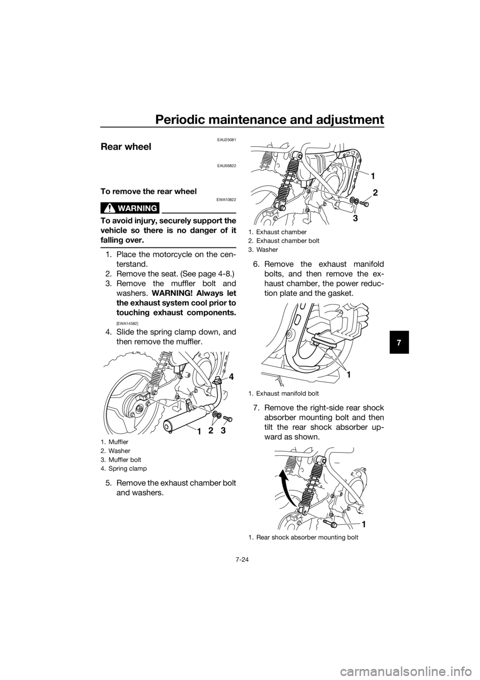
3. Remove the muffler bolt and washers. WARNING! Always let
the exhaust system cool prior to
touchin g exhaust components.
[EWA14582]
4. Slide the spring clamp down, and
then remove the muffler.
5. Remove the exhaust chamber bolt and washers. 6. Remove the exhaust manifold
bolts, and then remove the ex-
haust chamber, the power reduc-
tion plate and the gasket.
7. Remove the right-side rear shock absorber mounting bolt and then
tilt the rear shock absorber up-
ward as shown.
1. Muffler
2. Washer
3. Muffler bolt
4. Spring clamp
312 4
1. Exhaust chamber
2. Exhaust chamber bolt
3. Washer
1. Exhaust manifold bolt
1. Rear shock absorber mounting bolt
2
1
3
1
1
U2SA82E0.book Page 24 Monday, June 8, 2015 1:09 PM
Page 66 of 80

Periodic maintenance an d a djustment
7-25
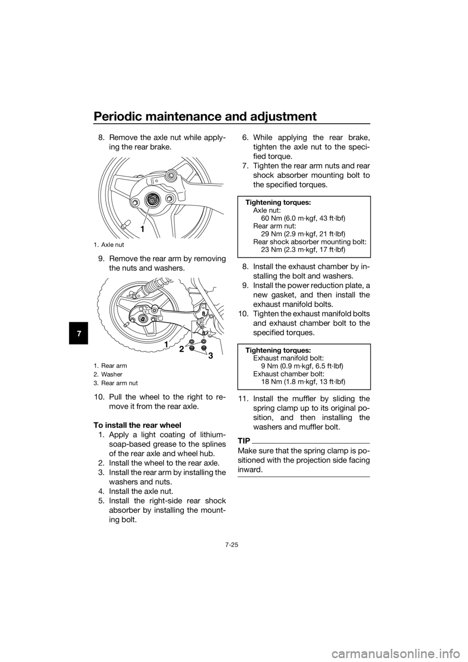
7 8. Remove the axle nut while apply-
ing the rear brake.
9. Remove the rear arm by removing the nuts and washers.
10. Pull the wheel to the right to re- move it from the rear axle.
To install the rear wheel 1. Apply a light coating of lithium- soap-based grease to the splines
of the rear axle and wheel hub.
2. Install the wheel to the rear axle.
3. Install the rear arm by installing the washers and nuts.
4. Install the axle nut.
5. Install the right-side rear shock absorber by installing the mount-
ing bolt. 6. While applying the rear brake,
tighten the axle nut to the speci-
fied torque.
7. Tighten the rear arm nuts and rear shock absorber mounting bolt to
the specified torques.
8. Install the exhaust chamber by in- stalling the bolt and washers.
9. Install the power reduction plate, a new gasket, and then install the
exhaust manifold bolts.
10. Tighten the exhaust manifold bolts and exhaust chamber bolt to the
specified torques.
11. Install the muffler by sliding the spring clamp up to its original po-
sition, and then installing the
washers and muffler bolt.
TIP
Make sure that the spring clamp is po-
sitioned with the projection side facing
inward.
1. Axle nut
1. Rear arm
2. Washer
3. Rear arm nut
1
12
3
Tightening torques:
Axle nut: 60 Nm (6.0 m·kgf, 43 ft·lbf)
Rear arm nut:
29 Nm (2.9 m·kgf, 21 ft·lbf)
Rear shock absorber mounting bolt: 23 Nm (2.3 m·kgf, 17 ft·lbf)
Ti ghtening torques:
Exhaust manifold bolt:
9 Nm (0.9 m·kgf, 6.5 ft·lbf)
Exhaust chamber bolt: 18 Nm (1.8 m·kgf, 13 ft·lbf)
U2SA82E0.book Page 25 Monday, June 8, 2015 1:09 PM