lock YAMAHA SLIDER 50 2014 Owners Manual
[x] Cancel search | Manufacturer: YAMAHA, Model Year: 2014, Model line: SLIDER 50, Model: YAMAHA SLIDER 50 2014Pages: 68, PDF Size: 2.03 MB
Page 6 of 68

TABLE OF CONTENTSSAFETY INFORMATION.................. 1-1
Further safe-riding points ............... 1-5
DESCRIPTION.................................. 2-1
Left view ......................................... 2-1
Right view ....................................... 2-2
Controls and instruments ............... 2-3
INSTRUMENT AND CONTROL
FUNCTIONS...................................... 3-1
Main switch/steering lock............... 3-1
Indicator lights and warning
lights............................................ 3-2
Speedometer unit ........................... 3-3
Handlebar switches ........................ 3-3
Front brake lever ............................ 3-4
Rear brake lever ............................. 3-4
Fuel and 2-stroke engine oil tank
caps ............................................ 3-5
Fuel ................................................. 3-5
Catalytic converter ......................... 3-6
2-stroke engine oil .......................... 3-7
Starter (choke) lever ...................... 3-7
Kickstarter ...................................... 3-8
Seat ................................................ 3-8
Anti-theft device housing ............... 3-8
Luggage hook................................. 3-9FOR YOUR SAFETY –
PRE-OPERATION CHECKS............. 4-1
OPERATION AND IMPORTANT
RIDING POINTS................................ 5-1
Starting a cold engine ..................... 5-1
Starting a warm engine ................... 5-2
Starting off ...................................... 5-2
Acceleration and deceleration ........ 5-3
Braking ............................................ 5-3
Tips for reducing fuel
consumption ................................ 5-4
Engine break-in ............................... 5-4
Parking ............................................ 5-5
PERIODIC MAINTENANCE AND
ADJUSTMENT................................... 6-1
Periodic maintenance chart for the
emission control system .............. 6-2
General maintenance and
lubrication chart ........................... 6-3
Removing and installing the
cowling and panel........................ 6-6
Checking the spark plug ................. 6-7
Final transmission oil....................... 6-8
Cleaning the air filter element ......... 6-9
Adjusting the carburetor ............... 6-10
Checking the throttle grip free
play ............................................ 6-10
Tires .............................................. 6-10
Cast wheels................................... 6-12Checking the front brake lever
free play..................................... 6-13
Adjusting the rear brake lever
free play..................................... 6-13
Checking the front brake pads
and rear brake shoes ............... 6-14
Checking the brake fluid level ...... 6-14
Changing the brake fluid .............. 6-15
Checking and lubricating the
cables ........................................ 6-16
Checking and lubricating the
throttle grip and cable ............... 6-16
Lubricating the front and rear
brake levers ............................... 6-16
Checking and lubricating the
centerstand ............................... 6-17
Checking the front fork ................. 6-18
Checking the steering................... 6-18
Checking the wheel bearings ....... 6-19
Battery .......................................... 6-19
Replacing the fuse ........................ 6-21
Replacing the headlight bulb ........ 6-21
Replacing the tail/brake light
bulb ........................................... 6-22
Replacing a turn signal light
bulb ........................................... 6-22
Troubleshooting............................ 6-23
Troubleshooting chart .................. 6-24
SCOOTER CARE AND STORAGE... 7-1
Matte color caution......................... 7-1U1S0E2E0.book Page 1 Thursday, July 25, 2013 6:53 PM
Page 14 of 68
DESCRIPTION
2-1
2
EAU10411
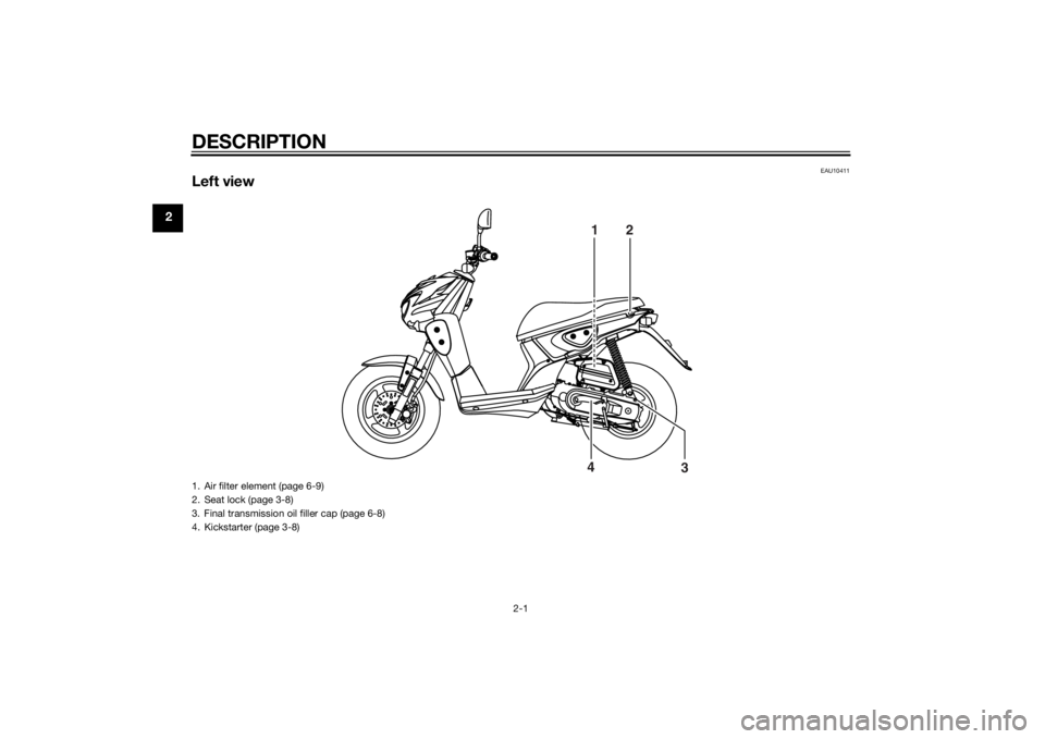
Left view
12
3 4
1. Air filter element (page 6-9)
2. Seat lock (page 3-8)
3. Final transmission oil filler cap (page 6-8)
4. Kickstarter (page 3-8)U1S0E2E0.book Page 1 Thursday, July 25, 2013 6:53 PM
Page 16 of 68
DESCRIPTION
2-3
2
EAU10431
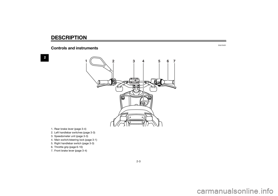
Controls and instruments
1
234567
1. Rear brake lever (page 3-4)
2. Left handlebar switches (page 3-3)
3. Speedometer unit (page 3-3)
4. Main switch/steering lock (page 3-1)
5. Right handlebar switch (page 3-3)
6. Throttle grip (page 6-10)
7. Front brake lever (page 3-4)U1S0E2E0.book Page 3 Thursday, July 25, 2013 6:53 PM
Page 17 of 68
INSTRUMENT AND CONTROL FUNCTIONS
3-1
3
EAU10462
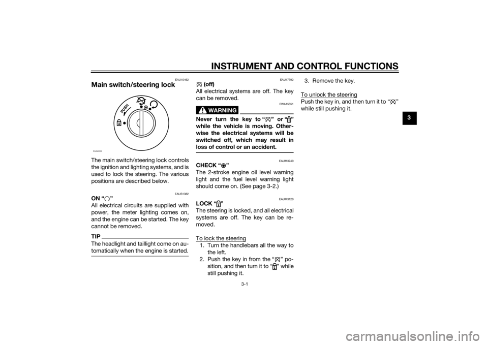
Main switch/steering lockThe main switch/steering lock controls
the ignition and lighting systems, and is
used to lock the steering. The various
positions are described below.
EAUS1382
ON “ ”
All electrical circuits are supplied with
power, the meter lighting comes on,
and the engine can be started. The key
cannot be removed.TIPThe headlight and taillight come on au-
tomatically when the engine is started.
EAU47792
(off)
All electrical systems are off. The key
can be removed.
WARNING
EWA15351
Never turn the key to “ ” or “ ”
while the vehicle is moving. Other-
wise the electrical systems will be
switched off, which may result in
loss of control or an accident.
EAUM3240
CHECK “ ”
The 2-stroke engine oil level warning
light and the fuel level warning light
should come on. (See page 3-2.)
EAUM3120
LOCK “ ”
The steering is locked, and all electrical
systems are off. The key can be re-
moved.
To lock the steering1. Turn the handlebars all the way to
the left.
2. Push the key in from the “ ” po-
sition, and then turn it to “ ” while
still pushing it.3. Remove the key.
To unlock the steering
Push the key in, and then turn it to “ ”
while still pushing it.
P
U
S
H
ZAUM0332
U1S0E2E0.book Page 1 Thursday, July 25, 2013 6:53 PM
Page 21 of 68
INSTRUMENT AND CONTROL FUNCTIONS
3-5
3
EAU13203
Fuel and 2-stroke engine oil
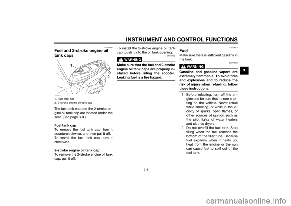
tank capsThe fuel tank cap and the 2-stroke en-
gine oil tank cap are located under the
seat. (See page 3-8.)
Fuel tank cap
To remove the fuel tank cap, turn it
counterclockwise, and then pull it off.
To install the fuel tank cap, turn it
clockwise.
2-stroke engine oil tank cap
To remove the 2-stroke engine oil tank
cap, pull it off.To install the 2-stroke engine oil tank
cap, push it into the oil tank opening.
WARNING
EWA10142
Make sure that the fuel and 2-stroke
engine oil tank caps are properly in-
stalled before riding the scooter.
Leaking fuel is a fire hazard.
EAU13213
FuelMake sure there is sufficient gasoline in
the tank.
WARNING
EWA10882
Gasoline and gasoline vapors are
extremely flammable. To avoid fires
and explosions and to reduce the
risk of injury when refueling, follow
these instructions.1. Before refueling, turn off the en-
gine and be sure that no one is sit-
ting on the vehicle. Never refuel
while smoking, or while in the vi-
cinity of sparks, open flames, or
other sources of ignition such as
the pilot lights of water heaters
and clothes dryers.
2. Do not overfill the fuel tank. Stop
filling when the fuel reaches the
bottom of the filler tube. Because
fuel expands when it heats up,
heat from the engine or the sun
can cause fuel to spill out of the
fuel tank.
1. Fuel tank cap
2. 2-stroke engine oil tank cap
2 1
ZAUM0144
U1S0E2E0.book Page 5 Thursday, July 25, 2013 6:53 PM
Page 24 of 68
INSTRUMENT AND CONTROL FUNCTIONS
3-8
3
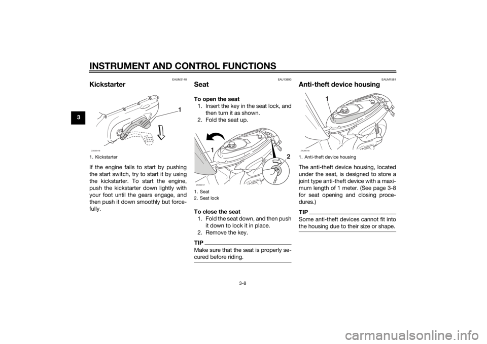
EAUM3140
KickstarterIf the engine fails to start by pushing
the start switch, try to start it by using
the kickstarter. To start the engine,
push the kickstarter down lightly with
your foot until the gears engage, and
then push it down smoothly but force-
fully.
EAU13893
SeatTo open the seat
1. Insert the key in the seat lock, and
then turn it as shown.
2. Fold the seat up.
To close the seat
1. Fold the seat down, and then push
it down to lock it in place.
2. Remove the key.TIPMake sure that the seat is properly se-
cured before riding.
EAUM1581
Anti-theft device housingThe anti-theft device housing, located
under the seat, is designed to store a
joint type anti-theft device with a maxi-
mum length of 1 meter. (See page 3-8
for seat opening and closing proce-
dures.)TIPSome anti-theft devices cannot fit into
the housing due to their size or shape.
1. Kickstarter
1
ZAUM0146
1. Seat
2. Seat lock
1
2
ZAUM0147
1. Anti-theft device housing
1
ZAUM0148
U1S0E2E0.book Page 8 Thursday, July 25, 2013 6:53 PM
Page 47 of 68
PERIODIC MAINTENANCE AND ADJUSTMENT
6-15
6 Insufficient brake fluid may al-
low air to enter the brake sys-
tem, reducing braking
performance.
Clean the filler cap before re-
moving. Use only DOT 3 or DOT
4 brake fluid from a sealed con-
tainer.
Use only the specified brake flu-
id; otherwise, the rubber seals
may deteriorate, causing leak-
age.
Refill with the same type of
brake fluid. Adding a brake fluid
other than DOT 3 or DOT 4 may
result in a harmful chemical re-
action.
Be careful that water does not
enter the brake fluid reservoir
when refilling. Water will signifi-
cantly lower the boiling point of
the fluid and may result in vapor
lock.
NOTICE
ECA17641
Brake fluid may damage painted
surfaces or plastic parts. Always
clean up spilled fluid immediately.
As the brake pads wear, it is normal for
the brake fluid level to gradually go
down. A low brake fluid level may indi-
cate worn brake pads and/or brake
system leakage; therefore, be sure to
check the brake pads for wear and the
brake system for leakage. If the brake
fluid level goes down suddenly, have a
Yamaha dealer check the cause before
further riding.
EAUM1361
Changing the brake fluidHave a Yamaha dealer change the
brake fluid at the intervals specified in
the periodic maintenance and lubrica-
tion chart. In addition, have the brake
hose replaced every four years or
whenever it is damaged or leaking.
U1S0E2E0.book Page 15 Thursday, July 25, 2013 6:53 PM
Page 53 of 68
PERIODIC MAINTENANCE AND ADJUSTMENT
6-21
6
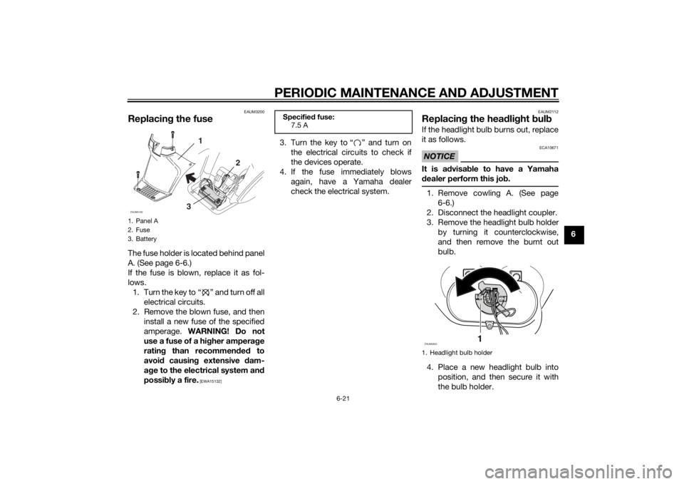
EAUM3200
Replacing the fuseThe fuse holder is located behind panel
A. (See page 6-6.)
If the fuse is blown, replace it as fol-
lows.
1. Turn the key to “ ” and turn off all
electrical circuits.
2. Remove the blown fuse, and then
install a new fuse of the specified
amperage. WARNING! Do not
use a fuse of a higher amperage
rating than recommended to
avoid causing extensive dam-
age to the electrical system and
possibly a fire.
[EWA15132]
3. Turn the key to “ ” and turn on
the electrical circuits to check if
the devices operate.
4. If the fuse immediately blows
again, have a Yamaha dealer
check the electrical system.
EAUM2112
Replacing the headlight bulbIf the headlight bulb burns out, replace
it as follows.NOTICE
ECA10671
It is advisable to have a Yamaha
dealer perform this job.1. Remove cowling A. (See page
6-6.)
2. Disconnect the headlight coupler.
3. Remove the headlight bulb holder
by turning it counterclockwise,
and then remove the burnt out
bulb.
4. Place a new headlight bulb into
position, and then secure it with
the bulb holder.
1. Panel A
2. Fuse
3. Battery
32 1
ZAUM0162
Specified fuse:
7.5 A
1. Headlight bulb holder
1
ZAUM0603
U1S0E2E0.book Page 21 Thursday, July 25, 2013 6:53 PM
Page 54 of 68
PERIODIC MAINTENANCE AND ADJUSTMENT
6-22
65. Connect the coupler.
6. Install the cowling.
7. Have a Yamaha dealer adjust the
headlight beam if necessary.
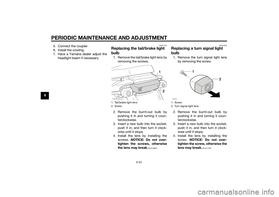
EAU24134
Replacing the tail/brake light
bulb1. Remove the tail/brake light lens by
removing the screws.
2. Remove the burnt-out bulb by
pushing it in and turning it coun-
terclockwise.
3. Insert a new bulb into the socket,
push it in, and then turn it clock-
wise until it stops.
4. Install the lens by installing the
screws. NOTICE: Do not over-
tighten the screws, otherwise
the lens may break.
[ECA10682]EAU24205
Replacing a turn signal light
bulb1. Remove the turn signal light lens
by removing the screw.
2. Remove the burnt-out bulb by
pushing it in and turning it coun-
terclockwise.
3. Insert a new bulb into the socket,
push it in, and then turn it clock-
wise until it stops.
4. Install the lens by installing the
screw. NOTICE: Do not over-
tighten the screw, otherwise the
lens may break.
[ECA11192]
1. Tail/brake light lens
2. Screw
1
2
ZAUM0532
1. Screw
2. Turn signal light lens
2 1
ZAUM0531
U1S0E2E0.book Page 22 Thursday, July 25, 2013 6:53 PM
Page 65 of 68

10-1
10
INDEX
22-stroke engine oil .................................. 3-7AAcceleration and deceleration ................ 5-3
Air filter element, cleaning ...................... 6-9
Anti-theft device housing ....................... 3-8BBattery .................................................. 6-19
Brake fluid, changing............................ 6-15
Brake fluid level, checking.................... 6-14
Brake lever, front .................................... 3-4
Brake lever, rear ..................................... 3-4
Brake levers, lubricating ....................... 6-16
Brake pads and shoes, checking ......... 6-14
Braking ................................................... 5-3CCables, checking and lubricating ......... 6-16
Carburetor,adjusting............................. 6-10
Care ........................................................ 7-1
Catalytic converter ................................. 3-6
Centerstand, checking and
lubricating........................................... 6-17
Cowling and panel, removing and
installing ............................................... 6-6DDimmer switch........................................ 3-4EEngine break-in ...................................... 5-4
Engine, starting a warm.......................... 5-2FFinal transmission oil .............................. 6-8
Front brake lever free play, checking ... 6-13
Front fork, checking ............................. 6-18
Fuel ......................................................... 3-5Fuel and 2-stroke engine oil tank
caps ..................................................... 3-5
Fuel consumption, tips for reducing ...... 5-4
Fuel level warning light........................... 3-2
Fuse, replacing..................................... 6-21
HHandlebar switches ............................... 3-3
Headlight bulb, replacing ..................... 6-21
High beam indicator light ....................... 3-2
Horn switch ............................................ 3-4IIdentification numbers ........................... 9-1
Indicator lights and warning lights ......... 3-2KKickstarter .............................................. 3-8LLuggage hook ........................................ 3-9MMain switch/steering lock ...................... 3-1
Maintenance and lubrication, periodic... 6-3
Maintenance, emission control
system ................................................. 6-2
Matte color, caution ............................... 7-1
Model label............................................. 9-1OOil level warning light ............................. 3-2PParking ................................................... 5-5
Part locations ......................................... 2-1RRear brake lever free play, adjusting.... 6-13SSafe-riding points................................... 1-5
Safety information .................................. 1-1Seat......................................................... 3-8
Spark plug, checking .............................. 6-7
Specifications ......................................... 8-1
Speedometer unit ................................... 3-3
Starter (choke) lever................................ 3-7
Starting a cold engine............................. 5-1
Starting off .............................................. 5-2
Start switch ............................................. 3-4
Steering, checking ................................ 6-18
Storage ................................................... 7-4
TTail/brake light bulb, replacing ............. 6-22
Throttle grip and cable, checking and
lubricating ........................................... 6-16
Throttle grip free play, checking ........... 6-10
Tires ...................................................... 6-10
Troubleshooting .................................... 6-23
Troubleshooting chart........................... 6-24
Turn signal indicator light ....................... 3-2
Turn signal light bulb, replacing............ 6-22
Turn signal switch ................................... 3-4VVehicle identification number ................. 9-1WWheel bearings, checking .................... 6-19
Wheels .................................................. 6-12
U1S0E2E0.book Page 1 Thursday, July 25, 2013 6:53 PM