stop start YAMAHA SUV 1200 2001 User Guide
[x] Cancel search | Manufacturer: YAMAHA, Model Year: 2001, Model line: SUV 1200, Model: YAMAHA SUV 1200 2001Pages: 135, PDF Size: 21.67 MB
Page 72 of 135
3-13
E
EJU00452a
Switches
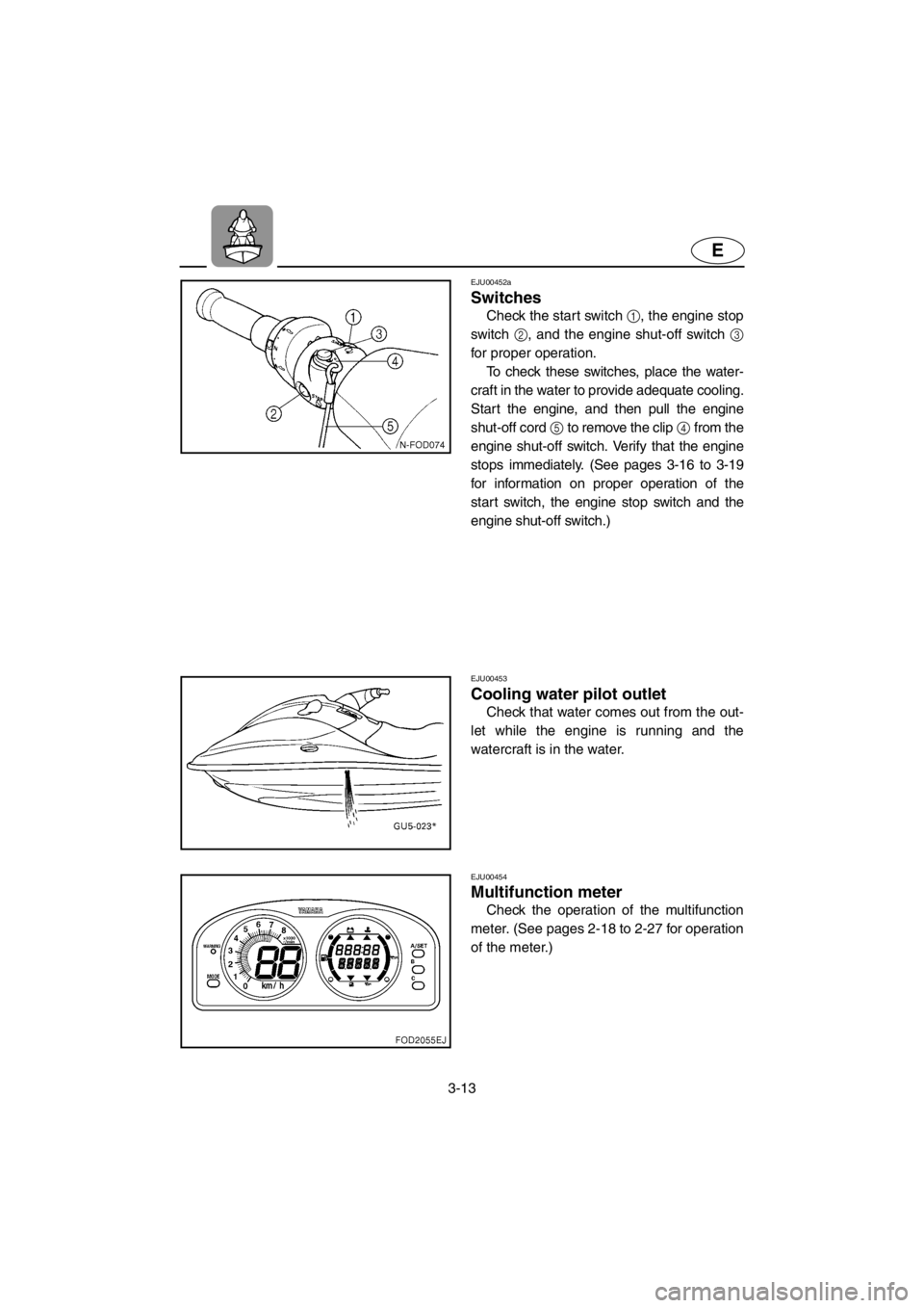
Check the start switch 1, the engine stop
switch 2, and the engine shut-off switch 3
for proper operation.
To check these switches, place the water-
craft in the water to provide adequate cooling.
Start the engine, and then pull the engine
shut-off cord 5 to remove the clip 4 from the
engine shut-off switch. Verify that the engine
stops immediately. (See pages 3-16 to 3-19
for information on proper operation of the
start switch, the engine stop switch and the
engine shut-off switch.)
EJU00453
Cooling water pilot outlet
Check that water comes out from the out-
let while the engine is running and the
watercraft is in the water.
EJU00454
Multifunction meter
Check the operation of the multifunction
meter. (See pages 2-18 to 2-27 for operation
of the meter.)
E_GU5-71-3.fm Page 13 Thursday, July 13, 2000 7:52 PM
Page 76 of 135
3-17
E
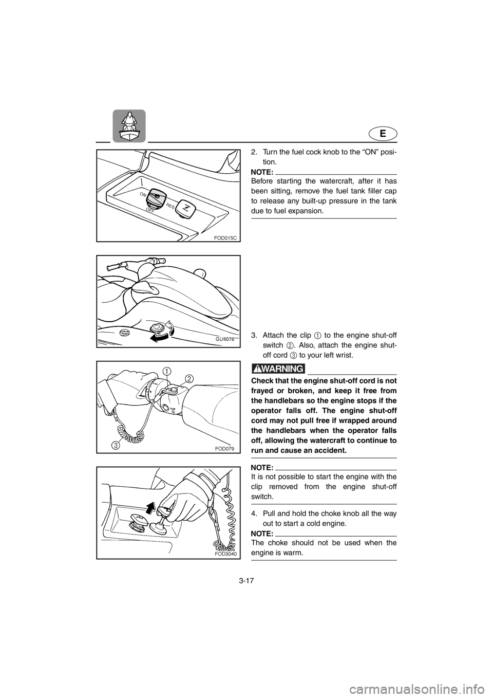
2. Turn the fuel cock knob to the “ON” posi-
tion.
NOTE:
Before starting the watercraft, after it has
been sitting, remove the fuel tank filler cap
to release any built-up pressure in the tank
due to fuel expansion.
3. Attach the clip 1 to the engine shut-off
switch 2. Also, attach the engine shut-
off cord 3 to your left wrist.
WARNING
Check that the engine shut-off cord is not
frayed or broken, and keep it free from
the handlebars so the engine stops if the
operator falls off. The engine shut-off
cord may not pull free if wrapped around
the handlebars when the operator falls
off, allowing the watercraft to continue to
run and cause an accident.
NOTE:
It is not possible to start the engine with the
clip removed from the engine shut-off
switch.
4. Pull and hold the choke knob all the way
out to start a cold engine.
NOTE:
The choke should not be used when the
engine is warm.
E_GU5-71-3.fm Page 17 Thursday, July 13, 2000 7:52 PM
Page 78 of 135
3-19
E
EJU00463a
Stopping the engine
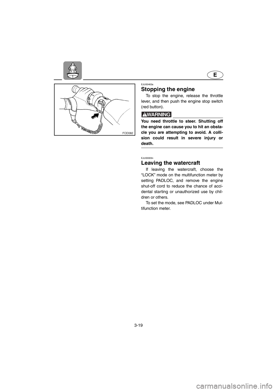
To stop the engine, release the throttle
lever, and then push the engine stop switch
(red button).
WARNING
You need throttle to steer. Shutting off
the engine can cause you to hit an obsta-
cle you are attempting to avoid. A colli-
sion could result in severe injury or
death.
EJU00005n
Leaving the watercraft
If leaving the watercraft, choose the
“LOCK” mode on the multifunction meter by
setting PADLOC, and remove the engine
shut-off cord to reduce the chance of acci-
dental starting or unauthorized use by chil-
dren or others.
To set the mode, see PADLOC under Mul-
tifunction meter.
E_GU5-71-3.fm Page 19 Thursday, July 13, 2000 7:52 PM
Page 97 of 135
4-2
E
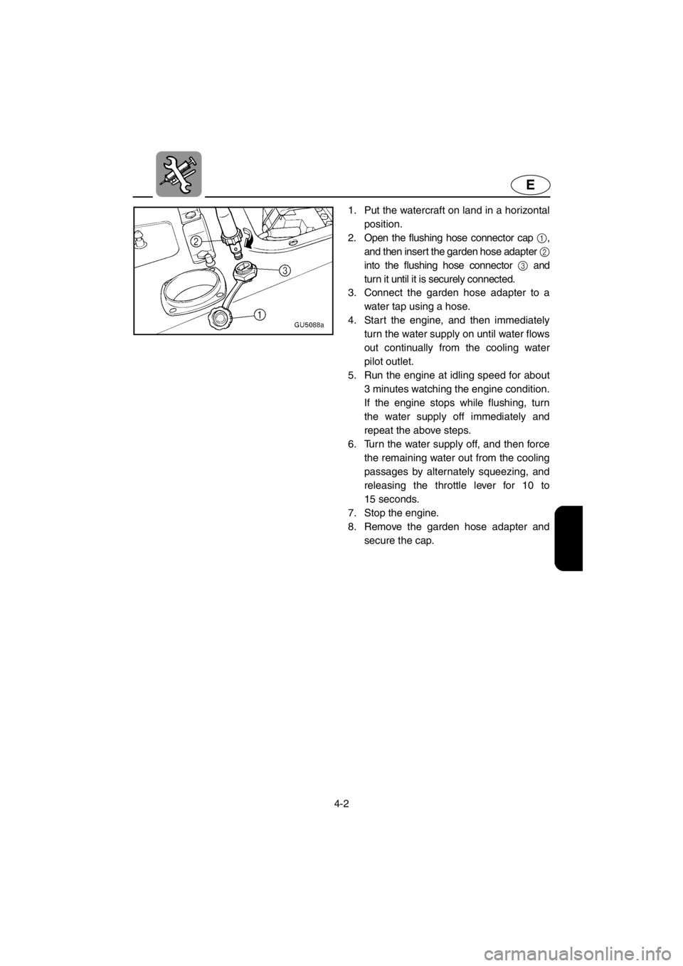
1. Put the watercraft on land in a horizontal
position.
2. Open the flushing hose connector cap 1,
and then inser t the garden hose adapter
2
into the flushing hose connector 3 and
turn it until it is securely connected.
3. Connect the garden hose adapter to a
water tap using a hose.
4. Start the engine, and then immediately
turn the water supply on until water flows
out continually from the cooling water
pilot outlet.
5. Run the engine at idling speed for about
3 minutes watching the engine condition.
If the engine stops while flushing, turn
the water supply off immediately and
repeat the above steps.
6. Turn the water supply off, and then force
the remaining water out from the cooling
passages by alternately squeezing, and
releasing the throttle lever for 10 to
15 seconds.
7. Stop the engine.
8. Remove the garden hose adapter and
secure the cap.
E_GU5-71-4.fm Page 2 Thursday, July 13, 2000 7:54 PM
Page 113 of 135
4-18
E
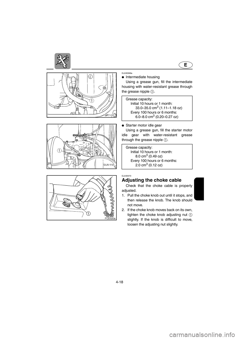
EJU00566a
●Intermediate housing
Using a grease gun, fill the intermediate
housing with water-resistant grease through
the grease nipple 1.
●Starter motor idle gear
Using a grease gun, fill the starter motor
idle gear with water-resistant grease
through the grease nipple 1. Grease capacity:
Initial 10 hours or 1 month:
33.0–35.0 cm
3 (1.11–1.18 oz)
Every 100 hours or 6 months:
6.0–8.0 cm
3 (0.20–0.27 oz)
Grease capacity:
Initial 10 hours or 1 month:
8.0 cm
3 (0.49 oz)
Every 100 hours or 6 months:
2.0 cm
3 (0.12 oz)
EJU00570
Adjusting the choke cable
Check that the choke cable is properly
adjusted.
1. Pull the choke knob out until it stops, and
then release the knob. The knob should
not move.
2. If the choke knob moves back on its own,
tighten the choke knob adjusting nut 1
slightly. If the knob is difficult to move,
loosen the adjusting nut slightly.
E_GU5-71-4.fm Page 18 Thursday, July 13, 2000 7:54 PM
Page 116 of 135
4-21
E
EJU00573
Adjusting the carburetor
The carburetor is a vital part of the engine
and requires very sophisticated adjustment.
Most adjusting should be left to a Yamaha
dealer who has the professional knowledge
and experience to perform it. However, the
operator may adjust the trolling speed as
part of the usual maintenance routine.
CAUTION:
The carburetor was set at the Yamaha
factory after many tests. If the settings
are disturbed by someone who does not
have the necessary technical knowledge,
poor engine performance and damage
may result.
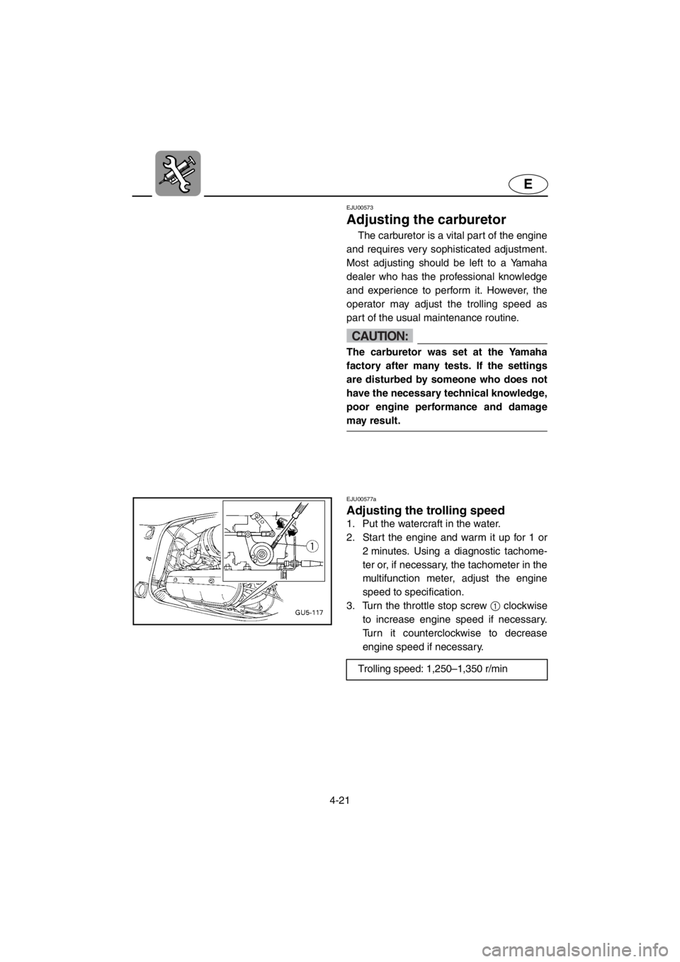
EJU00577a
Adjusting the trolling speed
1. Put the watercraft in the water.
2. Start the engine and warm it up for 1 or
2 minutes. Using a diagnostic tachome-
ter or, if necessary, the tachometer in the
multifunction meter, adjust the engine
speed to specification.
3. Turn the throttle stop screw 1 clockwise
to increase engine speed if necessary.
Turn it counterclockwise to decrease
engine speed if necessary.
Trolling speed: 1,250–1,350 r/min
E_GU5-71-4.fm Page 21 Thursday, July 13, 2000 7:54 PM
Page 130 of 135

6-1
E
EJU00609
Index
2-stroke engine oil ................................... 3-3
A
Adjusting the carburetor ........................ 4-21
Adjusting the choke cable ..................... 4-18
Adjusting the trolling speed ................... 4-21
Approval label of Emission control
certificate ................................................. 1-2
B
Battery .............................................. 3-8, 4-4
Battery warning indicator....................... 2-27
Beaching the watercraft ........................ 3-31
Bilge ........................................................ 3-7
Bleeding the oil injection pump ............. 4-22
Boarding alone ...................................... 3-24
Boarding and starting in deep water ..... 3-24
Boarding with passengers ..................... 3-25
Bow down.............................................. 2-15
Bow up .................................................. 2-15
C
Capsized watercraft .............................. 3-26
Caution labels ......................................... 1-8
Choke knob ............................................. 2-9
Cleaning and adjusting the spark
plugs...................................................... 4-14
Cleaning the jet intake and impeller ........ 5-4
Cleaning the watercraft ........................... 4-5
Clock ..................................................... 2-23
Connecting the jumper cables................. 5-6
Cooling water pilot outlet .............. 2-11, 3-13
Cruising limitations ................................ 1-11
D
Docking the watercraft .......................... 3-31
E
Emergency procedures ........................... 5-4
Emission control information ................... 1-2
Engine break-in ..................................... 3-14
Engine compartment ............................... 3-6
Engine oil meter .................................... 2-23
Engine overheat warning indicator ........ 2-26
Engine overheat warning system .......... 2-16Engine serial number .............................. 1-1
Engine shut-off cord (lanyard) ............... 3-12
Engine shut-off switch ............................. 2-9
Engine stop switch .................................. 2-9
Enjoy your watercraft responsibly ......... 1-18
F
Filling the fuel tank .................................. 3-3
Filling the oil tank .................................... 3-4
Fire extinguisher ...................................... 3-9
Flushing the cooling system .................... 4-1
Front seat ................................................ 2-5
Front storage compartment ................... 2-28
Fuel and oil.............................................. 3-1
Fuel and oil systems ............................... 3-6
Fuel cock knob ........................................ 2-8
Fuel filter ............................................... 4-10
Fuel meter ............................................. 2-22
Fuel system ............................................. 4-4
Fuel tank ............................................... 4-10
Fuel tank filler cap ................................... 2-7
Fuel warning indicator ........................... 2-25
G
Gasohol ................................................... 3-2
Gasoline .................................................. 3-1
Getting to know your watercraft ............ 3-20
Glove compartment ............................... 2-29
H
Handgrip ................................................ 2-17
Hazard information ................................ 1-14
Hood........................................................ 2-6
Hour meter ............................................ 2-24
Hull Identification Number (HIN).............. 1-1
I
Identification numbers ............................. 1-1
Important labels ....................................... 1-3
Inspecting and adjusting the throttle
cable...................................................... 4-12
Inspecting the battery ............................ 4-19
Inspecting the fuel system ....................... 4-9
Inspecting the oil injection system ......... 4-11
Inspecting the QSTS mechanism .......... 4-13
Inspecting the shift cable ....................... 4-12
Inspecting the steering cable................ 4-12
E_GU5-71IX.fm Page 1 Thursday, July 13, 2000 7:56 PM
Page 131 of 135

6-2
E
J
Jet unit................................................... 3-12
Jumping the battery................................. 5-5
L
Label location .......................................... 1-3
Launching the watercraft ....................... 3-16
Learning to operate your watercraft ...... 3-20
Leaving the watercraft ........................... 3-19
Limitations on who may operate the
watercraft .............................................. 1-10
Location of main components ................. 2-1
Lubrication............................................... 4-3
Lubrication points .................................. 4-15
M
Maintenance and adjustments ................ 4-6
Multifunction meter ....................... 2-18, 3-13
O
Oil filter .................................................. 4-11
Oil tank .................................................. 4-11
Oil tank filler cap...................................... 2-7
Oil warning indicator.............................. 2-26
Operating your watercraft...................... 3-20
Operation .............................................. 3-14
Operation of controls and other
functions .................................................. 2-4
Operation requirements ........................ 1-12
Other labels ............................................. 1-9
Owner’s/Operator’s Manual and tool
kit............................................................. 4-7
P
PADLOC initial setting........................... 2-19
PADLOC (Programmable digital locking
ignition).................................................. 2-19
Periodic maintenance chart..................... 4-8
Post-operation checks........................... 3-33
Pre-operation check list........................... 3-5
Pre-operation check points ..................... 3-6
Pre-operation checks .............................. 3-5
Primary Identification (PRI-ID) number ... 1-1
Q
Quick Shift Trim System (QSTS)
selector.................................................. 2-14R
Rear seat................................................. 2-4
Rear storage compartments .................. 2-30
Replacing the fuse ................................ 4-22
Reverse on waterways .......................... 3-32
Riding watercraft with passengers ........ 3-21
Rough water operation .......................... 3-32
S
Safe boating rules ................................. 1-17
Safety information ................................. 1-10
Selecting “PADLOC” mode ................... 2-20
Shift lever .............................................. 2-13
Shift lever and reverse gate.................. 3-11
Side grips .............................................. 2-17
Specifications ........................................ 4-23
Speedometer......................................... 2-22
Starting and boarding in shallow
water ..................................................... 3-23
Starting from a dock .............................. 3-23
Starting the engine ................................ 3-16
Starting the watercraft ........................... 3-22
Start switch............................................ 2-10
Steering system ...........................2-11, 3-10
Stopping the engine .............................. 3-19
Stopping the watercraft ......................... 3-30
Storage.................................................... 4-1
Storage compartments .......................... 2-28
Submerged watercraft ............................. 5-8
Switches ................................................ 3-13
T
Tachometer ........................................... 2-21
Throttle .................................................. 3-10
Throttle lever ......................................... 2-10
Tilt lever ................................................. 2-12
Towing the watercraft .............................. 5-7
Transporting .......................................... 3-35
Tripmeter ............................................... 2-25
Trip timer ............................................... 2-24
Troubleshooting ...................................... 5-1
Troubleshooting chart ............................. 5-1
Turning the watercraft ........................... 3-28
E_GU5-71IX.fm Page 2 Thursday, July 13, 2000 7:56 PM