light YAMAHA T110C 2014 User Guide
[x] Cancel search | Manufacturer: YAMAHA, Model Year: 2014, Model line: T110C, Model: YAMAHA T110C 2014Pages: 82, PDF Size: 2.06 MB
Page 28 of 82
OPERATION AND IMPORTANT RIDING POINTS
5-1
5
EAU15951
Read the Owner’s Manual carefully to
become familiar with all controls. If
there is a control or function you do not
understand, ask your Yamaha dealer.
WARNING
EWA10271
Failure to familiarize yourself with
the controls can lead to loss of con-
trol, which could cause an accident
or injury.
EAU47852
Starting and warming up a
cold engine 1. Turn the key to “ ”.
2. Shift the transmission into the neu-
tral position. The neutral indicator
light should come on. If not, ask a
Yamaha dealer to check the elec-
trical circuit.
3. Place the vehicle on the center-
stand.
WARNING
EWA14200
Before starting the engine, make
sure the transmission is in neutral
and that the vehicle is placed on the
centerstand.4. Turn the starter (choke) on and
completely close the throttle. (See
page 3-7.)
5. Start the engine by pushing the
start switch or by pushing the kick-
starter lever down.
If the engine fails to start by push-
ing the start switch, release the
switch, wait a few seconds, and
then try again. Each starting at-
tempt should be as short as possi-ble to preserve the battery. Do not
crank the engine more than 10
seconds on any one attempt. If the
engine does not start with the
starter motor, try using the kick-
starter.
6. After starting the engine, move the
starter (choke) back halfway.
7. When the engine is warm, turn the
starter (choke) off.
TIPThe engine is warm when it responds
quickly to the throttle with the starter
(choke) turned off.NOTICE
ECA11042
For maximum engine life, never ac-
celerate hard when the engine is
cold!
U40BE2E0.book Page 1 Wednesday, October 10, 2012 8:01 AM
Page 29 of 82
OPERATION AND IMPORTANT RIDING POINTS
5-2
5
EAU16640
Starting a warm engine Follow the same procedure as for start-
ing a cold engine with the exception
that the starter (choke) is not required
when the engine is warm.
EAU47840
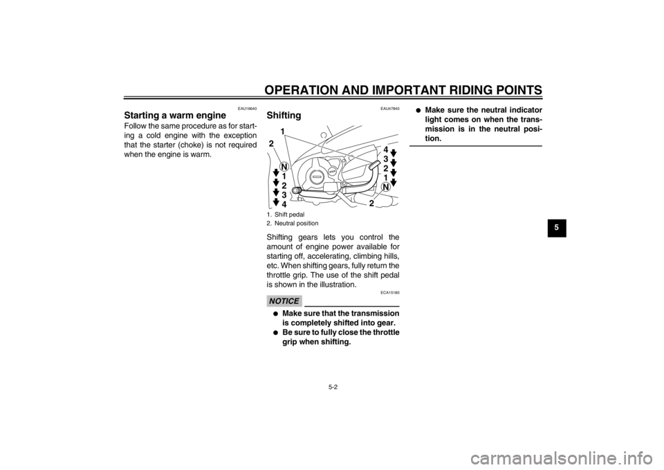
Shifting Shifting gears lets you control the
amount of engine power available for
starting off, accelerating, climbing hills,
etc. When shifting gears, fully return the
throttle grip. The use of the shift pedal
is shown in the illustration.NOTICE
ECA15180
●
Make sure that the transmission
is completely shifted into gear.
●
Be sure to fully close the throttle
grip when shifting.
●
Make sure the neutral indicator
light comes on when the trans-
mission is in the neutral posi-
tion.
1. Shift pedal
2. Neutral position
1
2
21
2
3
4 N
N3
2
1 4
U40BE2E0.book Page 2 Wednesday, October 10, 2012 8:01 AM
Page 30 of 82
OPERATION AND IMPORTANT RIDING POINTS
5-3
5
EAU16800
Tips for reducing fuel con-
sumption Fuel consumption depends largely on
your riding style. Consider the following
tips to reduce fuel consumption:●
Turn the starter (choke) off as
soon as possible.
●
Shift up swiftly, and avoid high en-
gine speeds during acceleration.
●
Do not rev the engine while shifting
down, and avoid high engine
speeds with no load on the engine.
●
Turn the engine off instead of let-
ting it idle for an extended length of
time (e.g., in traffic jams, at traffic
lights or at railroad crossings).
EAU16830
Engine break-in There is never a more important period
in the life of your engine than the period
between 0 and 1000 km (600 mi). For
this reason, you should read the follow-
ing material carefully.
Since the engine is brand new, do not
put an excessive load on it for the first
1000 km (600 mi). The various parts in
the engine wear and polish themselves
to the correct operating clearances.
During this period, prolonged full-throt-
tle operation or any condition that might
result in engine overheating must be
avoided.
EAU16863
0–150 km (0–90 mi)
Avoid prolonged operation above 1/3
throttle.
After every hour of operation, stop the
engine, and then let it cool for five to ten
minutes.
Vary the engine speed from time to
time. Do not operate the engine at one
set throttle position.150–500 km (90–300 mi)
Avoid prolonged operation above 1/2
throttle.
500–1000 km (300–600 mi)
Avoid prolonged operation above 3/4
throttle. NOTICE: After 1000 km (600
mi) of operation, the engine oil must
be changed.
[ECA10281]
1000 km (600 mi) and beyond
The vehicle can now be operated nor-
mally.NOTICE
ECA10270
If any engine trouble should occur
during the engine break-in period,
immediately have a Yamaha dealer
check the vehicle.
U40BE2E0.book Page 3 Wednesday, October 10, 2012 8:01 AM
Page 37 of 82
PERIODIC MAINTENANCE AND ADJUSTMENT
6-6
6
EAU18660
TIP●
The air filter needs more frequent service if you are riding in unusually wet or dusty areas.
●
Hydraulic brake service
Regularly check and, if necessary, correct the brake fluid level.
Every two years replace the internal components of the brake master cylinder and caliper, and change the brake fluid.
Replace the brake hoses every four years and if cracked or damaged.
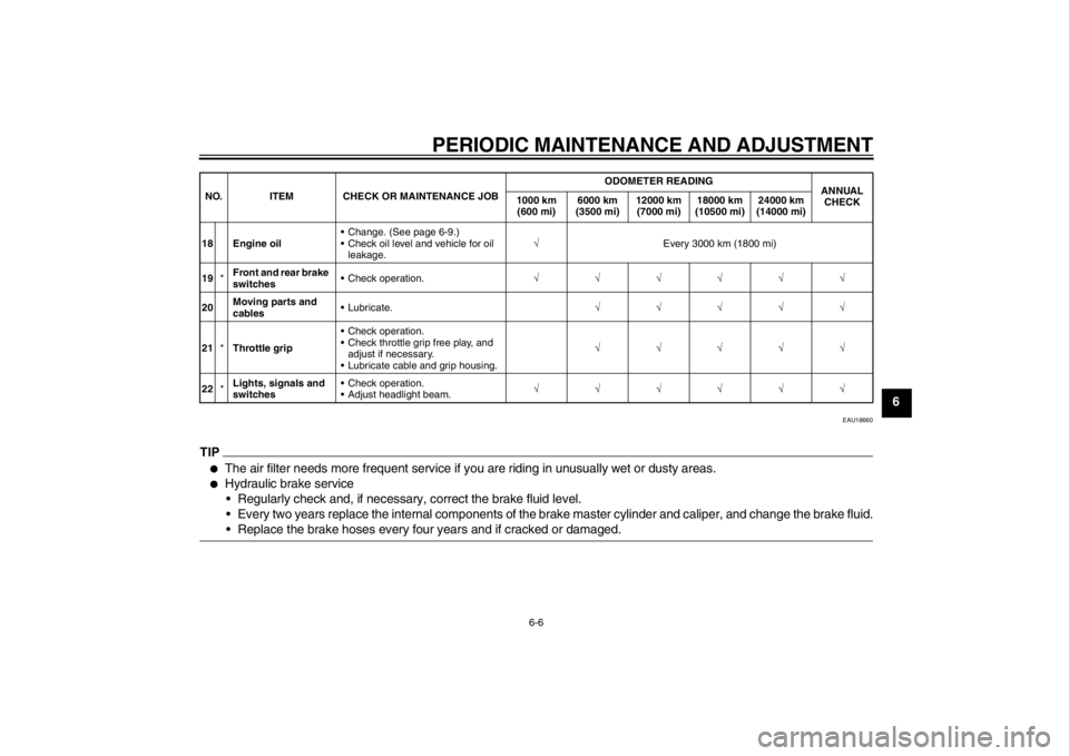
18 Engine oil Change. (See page 6-9.)
Check oil level and vehicle for oil
leakage.√Every 3000 km (1800 mi)
19*Front and rear brake
switches Check operation.√√√√√√
20Moving parts and
cables Lubricate.√√√√√
21*Throttle grip Check operation.
Check throttle grip free play, and
adjust if necessary.
Lubricate cable and grip housing.√√√√√
22*Lights, signals and
switches Check operation.
Adjust headlight beam.√√√√√√ NO. ITEM CHECK OR MAINTENANCE JOBODOMETER READING
ANNUAL
CHECK 1000 km
(600 mi)6000 km
(3500 mi)12000 km
(7000 mi)18000 km
(10500 mi)24000 km
(14000 mi)
U40BE2E0.book Page 6 Wednesday, October 10, 2012 8:01 AM
Page 39 of 82
PERIODIC MAINTENANCE AND ADJUSTMENT
6-8
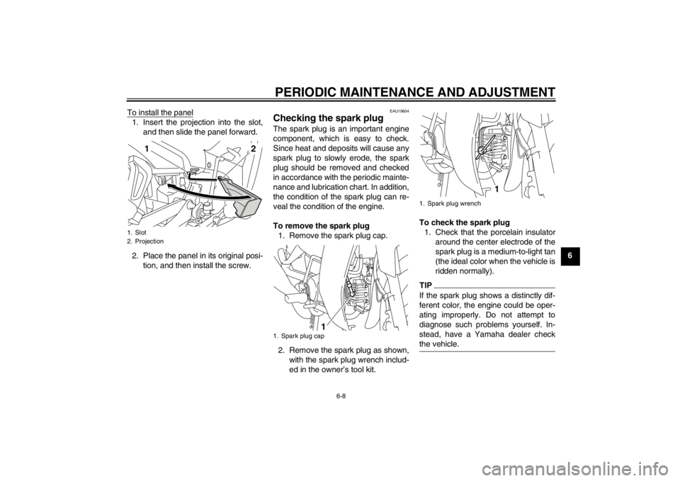
6 To install the panel
1. Insert the projection into the slot,
and then slide the panel forward.
2. Place the panel in its original posi-
tion, and then install the screw.
EAU19604
Checking the spark plug The spark plug is an important engine
component, which is easy to check.
Since heat and deposits will cause any
spark plug to slowly erode, the spark
plug should be removed and checked
in accordance with the periodic mainte-
nance and lubrication chart. In addition,
the condition of the spark plug can re-
veal the condition of the engine.
To remove the spark plug
1. Remove the spark plug cap.
2. Remove the spark plug as shown,
with the spark plug wrench includ-
ed in the owner’s tool kit.To check the spark plug
1. Check that the porcelain insulator
around the center electrode of the
spark plug is a medium-to-light tan
(the ideal color when the vehicle is
ridden normally).
TIPIf the spark plug shows a distinctly dif-
ferent color, the engine could be oper-
ating improperly. Do not attempt to
diagnose such problems yourself. In-
stead, have a Yamaha dealer check
the vehicle.
1. Slot
2. Projection
1
2
1. Spark plug cap
1
1. Spark plug wrench
1
U40BE2E0.book Page 8 Wednesday, October 10, 2012 8:01 AM
Page 40 of 82
PERIODIC MAINTENANCE AND ADJUSTMENT
6-9
62. Check the spark plug for electrode
erosion and excessive carbon or
other deposits, and replace it if
necessary.
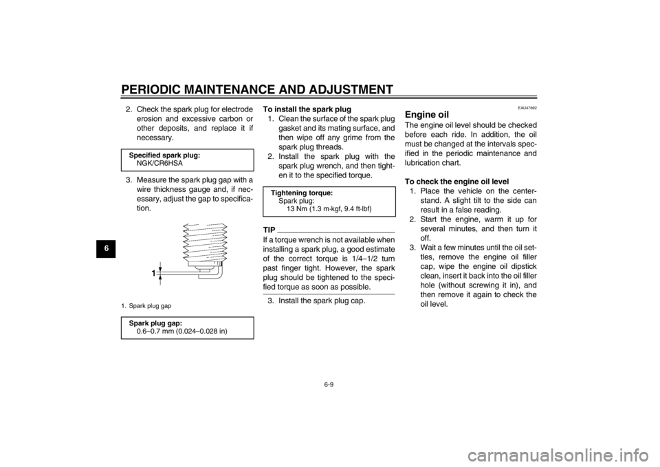
3. Measure the spark plug gap with a
wire thickness gauge and, if nec-
essary, adjust the gap to specifica-
tion.To install the spark plug
1. Clean the surface of the spark plug
gasket and its mating surface, and
then wipe off any grime from the
spark plug threads.
2. Install the spark plug with the
spark plug wrench, and then tight-
en it to the specified torque.
TIPIf a torque wrench is not available when
installing a spark plug, a good estimate
of the correct torque is 1/4–1/2 turn
past finger tight. However, the spark
plug should be tightened to the speci-
fied torque as soon as possible.3. Install the spark plug cap.
EAU47692
Engine oil The engine oil level should be checked
before each ride. In addition, the oil
must be changed at the intervals spec-
ified in the periodic maintenance and
lubrication chart.
To check the engine oil level
1. Place the vehicle on the center-
stand. A slight tilt to the side can
result in a false reading.
2. Start the engine, warm it up for
several minutes, and then turn it
off.
3. Wait a few minutes until the oil set-
tles, remove the engine oil filler
cap, wipe the engine oil dipstick
clean, insert it back into the oil filler
hole (without screwing it in), and
then remove it again to check the
oil level.
Specified spark plug:
NGK/CR6HSA1. Spark plug gapSpark plug gap:
0.6–0.7 mm (0.024–0.028 in)
Tightening torque:
Spark plug:
13 Nm (1.3 m·kgf, 9.4 ft·lbf)
U40BE2E0.book Page 9 Wednesday, October 10, 2012 8:01 AM
Page 42 of 82
PERIODIC MAINTENANCE AND ADJUSTMENT
6-11
6addition, do not use oils labeled
“ENERGY CONSERVING II” or
higher.
●
Make sure that no foreign mate-
rial enters the crankcase.
6. Start the engine, and then let it idle
for several minutes while checking
it for oil leakage. If oil is leaking, im-
mediately turn the engine off and
check for the cause.
7. Turn the engine off, and then
check the oil level and correct it if
necessary.
EAU47771
Cleaning the air filter element The air filter element should be cleaned
or replaced at the intervals specified in
the periodic maintenance and lubrica-
tion chart. Clean or, if necessary, re-
place the air filter element more
frequently if you are riding in unusually
wet or dusty areas.
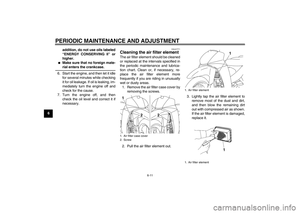
1. Remove the air filter case cover by
removing the screws.
2. Pull the air filter element out.3. Lightly tap the air filter element to
remove most of the dust and dirt,
and then blow the remaining dirt
out with compressed air as shown.
If the air filter element is damaged,
replace it.1. Air filter case cover
2. Screw1
22
1. Air filter element
1. Air filter element
1
U40BE2E0.book Page 11 Wednesday, October 10, 2012 8:01 AM
Page 48 of 82
PERIODIC MAINTENANCE AND ADJUSTMENT
6-17
6
EAU39813
Adjusting the brake pedal free
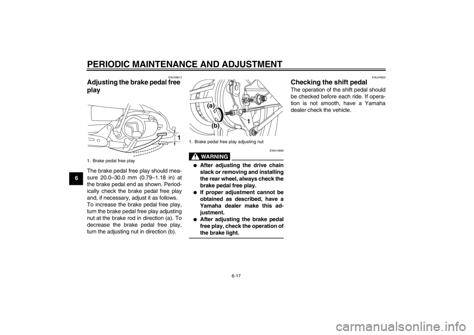
play The brake pedal free play should mea-
sure 20.0–30.0 mm (0.79–1.18 in) at
the brake pedal end as shown. Period-
ically check the brake pedal free play
and, if necessary, adjust it as follows.
To increase the brake pedal free play,
turn the brake pedal free play adjusting
nut at the brake rod in direction (a). To
decrease the brake pedal free play,
turn the adjusting nut in direction (b).
WARNING
EWA10680
●
After adjusting the drive chain
slack or removing and installing
the rear wheel, always check the
brake pedal free play.
●
If proper adjustment cannot be
obtained as described, have a
Yamaha dealer make this ad-
justment.
●
After adjusting the brake pedal
free play, check the operation of
the brake light.
EAU44820
Checking the shift pedal The operation of the shift pedal should
be checked before each ride. If opera-
tion is not smooth, have a Yamaha
dealer check the vehicle.
1. Brake pedal free play
1
1. Brake pedal free play adjusting nut
(a)(b)
1
U40BE2E0.book Page 17 Wednesday, October 10, 2012 8:01 AM
Page 49 of 82
PERIODIC MAINTENANCE AND ADJUSTMENT
6-18
6
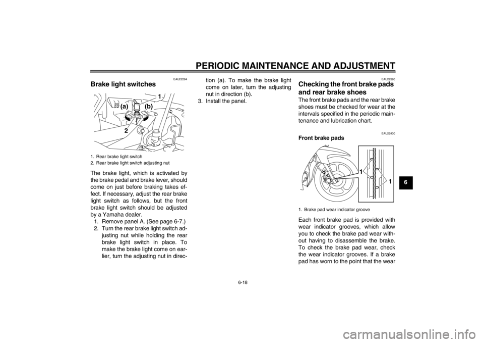
EAU22294
Brake light switches The brake light, which is activated by
the brake pedal and brake lever, should
come on just before braking takes ef-
fect. If necessary, adjust the rear brake
light switch as follows, but the front
brake light switch should be adjusted
by a Yamaha dealer.
1. Remove panel A. (See page 6-7.)
2. Turn the rear brake light switch ad-
justing nut while holding the rear
brake light switch in place. To
make the brake light come on ear-
lier, turn the adjusting nut in direc-tion (a). To make the brake light
come on later, turn the adjusting
nut in direction (b).
3. Install the panel.
EAU22380
Checking the front brake pads
and rear brake shoes The front brake pads and the rear brake
shoes must be checked for wear at the
intervals specified in the periodic main-
tenance and lubrication chart.
EAU22430
Front brake pads
Each front brake pad is provided with
wear indicator grooves, which allow
you to check the brake pad wear with-
out having to disassemble the brake.
To check the brake pad wear, check
the wear indicator grooves. If a brake
pad has worn to the point that the wear
1. Rear brake light switch
2. Rear brake light switch adjusting nut
21
(a) (b)
1. Brake pad wear indicator groove
1
1
U40BE2E0.book Page 18 Wednesday, October 10, 2012 8:01 AM
Page 53 of 82

PERIODIC MAINTENANCE AND ADJUSTMENT
6-22
6 5. Tighten both locknuts, and then
tighten the axle nut and brake
torque rod nut to their specified
torques.
TIPWhen tightening the axle nut, hold the
wheel axle with a wrench to keep it from
turning.6. Adjust the brake pedal free play.
(See page 6-17.) WARNING! Af-
ter adjusting the brake pedal
free play, check the operation of
the brake light.
[EWA16080]
7. Make sure that the drive chain pull-
ers are in the same position, the
drive chain slack is correct, and
the drive chain moves smoothly.
EAU23016
Cleaning and lubricating the
drive chain The drive chain must be cleaned and
lubricated at the intervals specified in
the periodic maintenance and lubrica-
tion chart, otherwise it will quickly wear
out, especially when riding in dusty or
wet areas. Service the drive chain as
follows.NOTICE
ECA10583
The drive chain must be lubricated
after washing the motorcycle, riding
in the rain or riding in wet areas.1. Remove all dirt and mud from the
drive chain with a brush or cloth.TIPFor a thorough cleaning, have a
Yamaha dealer remove the drive chain
and soak it in solvent.2. Spray Yamaha Chain and Cable
Lube or a high-quality spray-type
drive chain lubricant on the entire
chain, making sure that all side
plates and rollers have been suffi-
ciently oiled.
1. Alignment marks
2. Drive chain slack adjusting nut
3. Drive chain pullerTightening torques:
Locknut:
7 Nm (0.7 m·kgf, 5.1 ft·lbf)
Axle nut:
60 Nm (6.0 m·kgf, 43 ft·lbf)
Brake torque rod nut:
19 Nm (1.9 m·kgf, 14 ft·lbf)13
2
(a)
(b)
U40BE2E0.book Page 22 Wednesday, October 10, 2012 8:01 AM